
Introduction to CNC Machines
NC is a method of giving instructions to a machine in the form of a code.
NC machines do not have memory.
CNC has the same concepts as NC but uses a dedicated computer within the MCU.
All CNC machines are designed to fulfil three main objectives:
Note: CAD/CAM means Computer Aided Design/Computer Aided Manufacture.
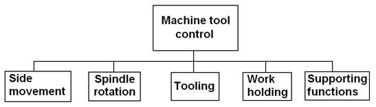
Figure 1 - Control System Fundamentals
Numerically controlled machines often weigh up to 100 tons and yet are required to position a cutting tool with accuracy of the order of 0.002mm. The control system must move the tool at feed rates as high as 8cm/sec while encountering loads which may vary dramatically on a given path. The NC machine must have dynamic response characteristics that enable it to follow intricate contours with a minimum of path error. Clearly, these requirements dictate a control system that is matched to the mechanical characteristics of the machine it drives.
A control system is a combination of devices that regulate an operation by administering the flow of energy and other resources to and from that operation. Essentially, a control system is made up of interrelated subsystems that perform tasks which in orthodox machining processes are managed by an intelligent human operator.
The control systems for NC machines therefore serve to replace the human machine operator and significantly improve upon even the best human performance. A direct analogy can be made between numerical controls and the human operators they replace. Both:
In summary, a machine control system is a combination of electronic circuitry, sensing devices and mechanical components which guide the cutting tool along a predefined path.
An operational numeric control system consists of the following three basic components:
The general relationship amount the three components is illustrated in Figure 2. The program of instructions serves as the input to the controller unit, which in turn commands the machine tool or other processes to be controlled.
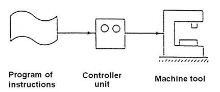
Figure 2 - Three Basic Components of a Numerical Control System
1. Program of instructions
The program of instructions is the detailed step-by-step set of directions which tells the machine tool what to do. It is coded in numerical or symbolic form on some type of input medium that can be interpreted by the controller unit.
2. Controller unit
The second basic component of the NC system is the controller unit. This consists of the electronics and hardware that read and interpret the program of instructions and convert it onto mechanical actions of the machine tool. The typical elements of the controller unit include the tape reader, a data buffer, signal output channels to the machine tool, feedback channels from the machine tool and the sequence controls to coordinate the overall operation of the forgoing elements.
3. Machine Tool
The third basic element of the NC system is the machine tool or other controlled process. It is the part of the NC system which performs the useful work.
Recent advances in CNC equipment for fabrication sheetmetal work and welding has resulted in an improvement in efficiency, quality and economics. Some of the machines responsible for this change are discussed below.
CNC power guillotines have not altered in size, style of capacity but have been retrofitted with NC or CNC controllers. The control unit along with a more sophisticated back gauge allows for greater accuracy (up to 0.1mm). The controller may have such features as:
Traditional methods of obtaining shapes, using Profile Cutting machines, require accurate templates to be made of drawings to be produced manually. This could be time consuming along with the problems of allowances and accuracy.
Current CNC machines provide considerable flexibility such as:
Perhaps one of the most spectacular advances is in the preparation of flat blank sheets, where notches, holes of different shapes and sizes and nibbled slots or shapes are required. The use of a multi tool turret (similar to machining centres) has been employed. Large quantities or even "one off'' complex shapes may be manufactured using these systems. Not only is production time reduced but also the Down Time along with an accuracy of 0.1mm makes this a desirable machine to have in a modern workshop.
Machine capacities vary from a 15 ton - 15 station machine (which will punch 8mm thick mild steel and has a max diameter of 50mm) to 30/40 ton machines with 72 stations (which have indexing and will punch 10mm thick plate and can have max diameters of ).
Presses as with CNC guillotines as mentioned earlier haven’t altered their physical design, for example machine capacity is still rated in Tons and machines may be “down stroke” or “up stroke” types. Rapid back gauge movement along with a CNC controller however gives for much more accuracy and consistent work. Other important features of the CNC controller on a press may be as follows:
As the processes of laser cutting and welding are developed further, savings may be made in the production of components manufactured from materials such as aluminium and stainless steel. The process is capable of great accuracy and cleanliness of cut; this coupled with the low distortion and very little waste make the process very desirable.
Where components are required to be assembled or offered to a machine (Machine loading) within a flat plane (i.e. using X & Y coordinates) various CNC assembly machines could be employed. However, in recent years robots have been developed for not only material handling but also welding. If various jigs, fixtures and manipulators are employed with robots then both spot welding and Metal Arc Gas Shielded (MAGS) processes can be used very successfully.
The future of CNC does not stop here, other areas which may be involved in the fabrication sheetmetal work and welding industries could be:
Numerically controlled machine tools are more expensive than conventional machines of equivalent size and type. The control system itself is costly and the more axes that need to be controlled the dearer the machine becomes.
It also follows that the more complex the machine the more need for adequate training, thus requiring more time and expense. The comparison of Advantages and Disadvantages between "conventional" machines and "CNC" machines is quite involved. The following are just pointers which may highlight some topical areas.
The advantages and disadvantages of CNC machines will also vary with the different types of firm and the type of work that firm encounter. The types of firm within the sheetmetal, fabrication and welding industry may range from:
Constructions details which makes a CNC machine different to a conventional one:
Advantages of CNC over conventional machines:
Conventional sheetmetal machines are dangerous and CNC machines are no different.
The Press Brake is one of the most dangerous sheetmetal machines both CNC and conventional. The turret punch is a much safer machine to use yet still there are dangers present.
Pressure mats and/or light barriers should be present and turned on. All moving parts are removed from possible contact with the operator. The work-piece moves around and care is needed at some stages in the operation.
It is important not to exceed the capacity of the machine and use correct clearances when installing tooling.
Hazards:
Source: http://local.ecollege.ie/Content/APPRENTICE/liu/sheetmetal_notes/module7/CNC%20Machines_M7_U2.doc
Web site to visit: http://local.ecollege.ie/
Author of the text: indicated on the source document of the above text
The Meaning Of Computer Numerical Control
Key Learning Points
Definition the meaning of computer numerical control.
The computer numerical control (CNC) machine has a built-in computer, which is used to store and send instructions to different parts of the machine in the form of code. The machine responds to this coded information in a precise and ordered manner to carry out various machining functions. Instructions are supplied to the machine as a series of blocks of information. A block of information is a group of commands sufficient to enable the machine to carry out one individual machining operation e.g. move the cutter form position 1 to position 2 at a specified feed rate.
2.0 The Differences Between CNC Machines Tools And Conventional Machine Tools
Key Learning Points
Machine axis determination for horizontal and vertical spindle machines. Constructional details e.g. special configurations to increase accuracy. Recirculating ball leadscrews and anti-friction slideways. Use of servo and stepping motors in slide movement. Visual displays unit – user interfaces. Swarf removal systems.
The primary axes of a machine are designated as X, Y, Z, which have positive and negative values. The Z-axis is always the main spindle axis and is positive away from the work, which is for safety reasons. The X-axis is always horizontal and parallel to the surface of the work. The Y-axis is perpendicular to both X and Z axes.
For the milling machine, the Z + direction is upwards away from the work, Z – direction is downwards into the work. The X + direction is to the right of the work and the X – direction to the left. The Y + direction is back into the machine and the Y- direction is directly towards the operator.
For the lathe, the Z + direction is to the right and away from the work, Z – direction is to the left and into the work. The X + direction is directly towards the operator, the X – direction is back into the machine away from the operator.
Ref: Timings, R.L. 1998, Manufacturing technology, vol. 1, 3rd edn, Pearson Education Limited, chapter 5, Numerical control part programming, sec. 5.4, Axis nomenclature, p. 176.
ISBN-13: 9780582356931
The conventional machine is designed to have an operator standing directly in front controlling the machine. For the CNC machine this is no longer required as the machine is operating under program control.
CNC machines have more rigid construction when compared to the conventional machine. The slide ways, guide and spindles of the CNC machine all look over proportioned when compared to the conventional machine. The structure of the CNC machine is therefore designed to cope with the torsional forces and heavy duty cutting imposed on these machines.
Ref: Timings, R.L. 1998, Manufacturing technology, vol. 1, 3rd edn, Pearson Education Limited, chapter 5, Numerical control part programming, sec. 53, Advantages and limitations, p. 173.
ISBN-13: 9780582356931
The slideways on a conventional machine operate under the conditions of sliding friction, where the friction is higher at lower velocities, which can result in jerky slide movements. To overcome this rolling friction can be used instead of sliding friction, where re-circulating roller bearings are positioned under the slideways. The leadscrews in conventional machines are usually of the Acme thread form, which are inefficient due to the high frictional resistance between the flanks of the screw and the nut. There is also backlash, because of the clearance between the screw and the nut. This has been replaced in the CNC machine with the re-circulating ball lead screw, where both the leadscrew and the nut have a precision ground radiused shaped thread. The space or track between the leadscrew and nut is filled with an endless stream or ball bearings. The advantages are longer life, less frictional resistance, lower torque required, more precise positioning of slides, where backlash is almost completely eliminated.
Ref: Timings, R.L. 1998, Manufacturing technology, vol. 1, 3rd edn, Pearson Education Limited, chapter 4, Kinematics of manufacturing equipment, sec. 4.5, 4.6, p. 153.
ISBN-13: 9780582356931
The slides and spindle of the CNC machine are driven by either stepper motor, which are used in an open-loop system or servo motors, which are used in a closed-loop system. Stepper motor – a digital signal is sent from the controller to the motor in the form of pulses, which will cause the motor to rotate through a specified angle, which causes the slide to move by the required distance, e.g. if five digital pulses are sent to the stepper motor then it will rotate by five steps, which is converted to linear movement by the leadscrew. The speed by which the pulses are sent to the stepper motor will determine the velocity of the slide movement. As the distance moved by the slide and the feed can be accurately controlled by the CNC control system, then there is no need for positional or velocity feedback. There are however some disadvantages associated with this open-loop system using stepper motors:
The stepper motors are only used on small low powered machines.
Servo Motor – the servo motor requires both positional and velocity feedback, which means that the actual position and velocity of the slideway is continuously compared to the digital signal that is being sent out by the controller. This therefore is a closed-loop system. The device used to provide feedback from the slide to the controller is a transducer, which converts mechanical displacement into an electrical signal.
Ref: Timings, R.L. 1998, Manufacturing technology, vol. 1, 3rd edn, Pearson Education Limited, chapter 5, Numerical control part programming, sec. 5.5, Control systems, p. 177.
ISBN-13: 9780582356931
The visual display unit (VDU), which is also called a monitor or a display is normally built-in to the side panel of the CNC machine. It visually lists the machining program in the form of G-codes and can also be used to show a graphical display of the path that the cutting tool will take to machine the part. A keyboard close to the VDU allows programs to be written directly into the controller unit of the machine or can be used to modify existing programs. It is more common nowadays to prepare the program on a separate computer and then load it onto the CNC machine later. The advantage of this is that the CNC machine is not idle while the program is being written.
When swarf builds up on the table of a conventional machine, it is usually removed by the machine operator. The build up is easily seen by the operator and removed when required. However for CNC machines swarf build-up is a problem due to the high rates of metal removal and the fact that CNC machines may not have an operator present during machining. Therefore in CNC machines have built in swarf removal equipment such as rotary screw or linear conveyors. Slanted beds in CNC lathes allow swarf to fall away into the base of the machine. Multiple coolant nozzles around the cutting zone can assist in removing swarf.
3.0 Advantages Of CNC Machines When Compared To Conventional Machines
Key Learning Points
Advantages of CNC machining: high accuracy and repeatability, production times, safety. Elimination of special jigs and fixtures. Reduction of machine set up times. Flexibility in changes of component design. Reduction of operation error. Complex one-off components and small batch quantities. Guarding arrangements for CNC machines. Adaptability and advantages of CNC within modern and evolving industries including the apprentices workplace.
Once the program has been written and proved, parts can be consistently machined to a high degree of accuracy and consistency. Production time can also be reduced due the fact that the tool can be feed at a rapid feed rate to the work. Also complex form tools are not required as the CNC machine can generate the required profile. Safety has also been improved as most CNC machines have safety features such as guards.
Ref: Timings, R.L. 1998, Manufacturing technology, vol. 1, 3rd edn, Pearson Education Limited, chapter 5, Numerical control part programming, sec. 5.3, Advantages and limitations, p. 173.
ISBN-13: 9780582356931
Production time can also be reduced and costs reduced due the fact that writing a part program is quicker and cheaper than manufacturing jigs and fixtures.
Setup times can be reduced when compared to the setup times on conventional machines due to the fact that equipment such as, the rotary table, jigs, fixtures, form tools etc., do not need to setup.
When the program is written to the drawing dimensions, a trial part is machined to prove the program. The machined part is rarely correct on the first run, therefore modifications will need to be made to the program to bring some features within the required tolerance band. This is easily done by calling up the program, which will be displayed on the screen. The operator then scrolls down to the line where the value needs to be changed. When the change is made the program can be run again. Also future design changes can be made in the same way.
Provided that the program is correct and the cutting tools are setup properly no errors will occur in the work. As explained above, the program is normally proved in advance of production. Operator fatigue, boredom or inattention will not affect the quality or the duration of machine as can occur when machining on a conventional machine.
CNC machines are ideal for one-off components and small batch quantities. The fast change-over times that can be achieved by the CNC machine means that small batches can be machined economically. The program needs to be prepared on a separate computer so that the CNC machine can remain in production. The program can be stored on the CNC machine and called up when required again in the future.
Safety has also been improved when compared to conventional machines, as most CNC machines have safety features such as guards. The machine is only accessible through the sliding doors that are closed prior to the machine starting up. Safety switches are placed behind the sliding doors will not allow the machine program to run until the doors are closed. Also, if the doors are opened the machine will switch off.
In the past it was adequate for the apprentice Toolmaker to be trained on conventional milling machines and the lathes. In order to use these machines effectively the apprentice had to learn to use other equipment such as the sine bar, rotary table, dividing head etc., on the milling machine and learn how to turn tapers, stepped diameters, threads etc., on the lathe. Nowadays the CNC machine is used through out industry. It can perform all the above tasks and can also be programmed and run by semi-skilled operators. It is still very important to be proficient in all aspects of the conventional milling machine and lathe, but learning to use the CNC machine is a necessary requirement of the modern day apprentice.
Summary
The meaning of computer numerical control: The computer numerical control (CNC) machine has a built-in computer, which is used to store and sent instructions to different parts of the machine in the form of code. The machine responds to this coded information in a precise and ordered manner to carry out various machining functions. Instructions are supplied to the machine as a series of blocks of information. A block of information is a group of commands sufficient to enable the machine to carry out one individual machining operation e.g. move the cutter form position 1 to position 2 at a specified feed rate.
The differences between CNC machines tools and conventional machine tools: The conventional machine is designed to have an operator standing directly in front controlling the machine. For the CNC machine this is no longer required as the machine is operating under program control.
CNC machines have more rigid construction when compared to the conventional machine. The slide ways, guide and spindles of the CNC machine all look over proportioned when compared to the conventional machine. The structure of the CNC machine is therefore designed to cope with the torsional forces and heavy duty cutting imposed on these machines. The quality of parts produced from a CNC machine is more consistent.
The slides and spindle of the CNC machine are driven by either stepper motor, which are used in an open-loop system or servo motors, which are used in a closed-loop system. The stepper motors are only used on small low powered machines.
Advantages of CNC machines when compared to conventional machines: Once the program has been written and proved, parts can be consistently machined to a high degree of accuracy and consistency. Production time can also be reduced due the fact that the tool can be feed at a rapid feed rate to the work. Also complex form tools are not required as the CNC machine can generate the required profile. Safety has also been improved as most CNC machines have safety features such as guards.
Suggested Exercises
Questions
Answers
Recommended Additional Resources
Black, Bruce J 2004, Workshop processes, practices and materials, 3rd edn, Elsevier Science & Technology.
ISBN-13: 9780750660730
Timings, R.L. 1998, Manufacturing technology, vol. 1, 3rd edn, Pearson Education Limited.
ISBN-13: 9780582356931
Source: http://local.ecollege.ie/Content/APPRENTICE/liu/toolmaking_notes/module6/m6_u1.doc
Web site to visit: http://local.ecollege.ie/
Author of the text: indicated on the source document of the above text
The first numerical controlled machine was developed in 1952. Instead of a sheet metal card or template, punched tape was used containing binary-coded data. For the first time a machine worked according to rules which had been condensed into a control programme.
The computer numerical control (CNC) machine has a built-in computer, which is used to store and send instructions to different parts of the machine in the form of code. The machine responds to this coded information in a precise and ordered manner to carry out various machining functions.
The first numerical controlled machine was developed in 1952. Instead of a sheet metal card or template, punched tape was used containing binary-coded data. For the first time a machine worked according to rules which had been condensed into a control programme. Machine movements were no longer activated by hand, but directly driven by a control programme.
A numerical control program contains all the necessary information for manufacturing a workpiece. This information is encoded and written in tabular form according to international established guidelines. The resulting table is the actual NC program.
The “instructions” are coded in numbers and letters. Letters and numbers are necessary to differentiate between motion information (positioning, for example, the traverse path for changing a tool), geometric information (e.g. circular motion, straight line motion), and technological information (e.g. punching, nibbling).
The computer numerical control (CNC) machine has a built-in computer, which is used to store and send instructions to different parts of the machine in the form of code. The machine responds to this coded information in a precise and ordered manner to carry out various machining functions. Instructions are supplied to the machine as a series of blocks of information. A block of information is a group of commands sufficient to enable the machine to carry out one individual machining operation e.g. move the cutter form position 1 to position 2 at a specified feed rate.
The most basic function of any CNC machine is automatic, precise, and consistent motion control. Rather than applying completely mechanical devices to cause motion as is required on most conventional machine tools, CNC machines allow motion control in a revolutionary manner. All forms of CNC equipment have two or more directions of motion, called axes. These axes can be precisely and automatically positioned along their lengths of travel. The two most common axis types are linear (driven along a straight path) and rotary (driven along a circular path).
The most common axis used in CNC machines are the X, Y and Z axis. However CNC machines are more flexible if they have a fourth axis, usually a rotary axis or even a fifth axis which offers even higher flexibility again. True complex and flexible five-axis CNC machines are usually found in the aircraft industry, where a multi-axis, simultaneous cutting motion is necessary to machine complex shapes and reach cavities and various angles. CNC machines can be constructed with special configurations to manufacture any conceivable part or product.

The programming language that CNC uses is called G-Code. These codes actually position the parts and do the work. To be able to have a machine work properly, you have to input the correct variables such as axes and reference points.
With both NC and CNC machines, coded information is programmed into the machine controller. With CNC machines computer software is used to create a program. Programs can then be downloaded or uploaded directly between a computer and the CNC machine controller. With NC machines you need to manually enter the coded information into the machine controller.
The program zero point establishes the point of reference for motion commands in a CNC program. This allows the programmer to specify movements from a common location. If program zero is chosen wisely, usually coordinates needed for the program can be taken directly from the print.
A Computer Numerical Controlled (CNC) machine may have more than one motion type that it uses, but there are three most common motion types that are easy to remember. These are the Rapid Motion, the Straight Line Motion, and the Circular Motion.
All of these motion types may seem different but they share two things in common, which would be that they are all modal and the endpoint of each motion is specified in motion command. By being modal it means that the motion type would be in effect until changed otherwise. There are 3 main motion types:
Rapid motion type is also called Positioning. The way this motion type is used is through utilizing the fastest rate possible of the command motion of the machine. Example uses of rapid motion are moving to clear obstructions, placing cutting tools to and from the desired position, and any program that provides non-cutting in their schemes.
The command that is usually programmed to a CNC machine is G00 because in this command, the end point for the rapid motion would be specified.
The CNC machine, with most controls given, will be able to move as fast as possible in all commanded axes. In the case of rapid motion, one axis may be able to reach its end point before other axes. Straight line movement will not occur with this type of rapid command function and the programmer of the machine must take into account that there are no obstructions to avoid. Straight line motion will happen even during rapid motion commands when done with other controls.
This type of motion would allow the programmer of the machine to command perfectly straight line movements within the machine. Unlike the rapid motion type, the straight line motion would allow the programmer to vary the rate of the motion or feed rate to be used during the movement. Examples of using straight line motion would be turning a straight diameter, taper, milling straight surfaces, and drilling.
The common word to specify a straight line motion into a machine would be G01, for within this command the programmer will include the preferred end point within each of the axes.
This motion type would cause the machine to move in the direction of a circular path and is used to generate the radii in machining. When talking about points on circular motion feed rate, it is equal to that of straight line motion.
Other than that of straight line motion and rapid motion, there are two G codes that are commonly used when programming a circular motion into a machine. These are G02 and G03. G02 is used when the programmer desires a clockwise motion into the machine while G03 is used to make an anti-clockwise motion. To know which of the commands to use, the programmer must view the movement with the same perspective as to what the motion of the machine will be, may it be clockwise or anti-clockwise.
Another requirement that would be programmed into a machine that would be the radius of the arc that is to be generated. With brand new technological advances in CNC, an “R” word is now used to specify the radius.
All types of CNC machine tools require some form/s of compensation. Though applied for different reasons on different machine types, all forms of compensation allow the CNC user to allow for unpredictable conditions related to tooling as the program is developed. Here are some compensations found on CNC machines:
All forms of compensation work with offsets. Offsets in a CNC control are storage locations into which numerical values can be placed. The numerical value of an offset has no meaning until it is referenced by a CNC program.
Offsets can be used for several purposes depending on the style of machine tool and type of compensation being used. Here are some of the more common applications for offsets:
These are "silly" mistakes on the programmer's part that cause a program to be unacceptable to the control. For example, maybe the programmer meant to type G01," but instead typed "G10." These mistakes are usually very easy to find, since the control will go into alarm state as soon as the command is read.
This kind of mistake is usually harder to find and correct. It could be caused by transposing numbers or letter addresses, but is usually the result of an incorrect calculation for coordinates to be used in the program. In some cases, the program will cause motion that appears to be correct, but does not machine the workpiece correctly.
Even a perfectly prepared program will behave poorly if setup mistakes are made. For example, the measurements of the program zero position and tool lengths must be correctly made and entered. Even something as basic as loading the tools into the proper stations should not be taken for granted.
Though the program's motions may be correct, the operator must be on guard for cutting condition problems. Feeds and speeds must be properly applied. While machining the first workpiece with any program, the operator must be very cautious, watching for possible machining problems.
Prior to letting a program cause motion, it is wise to let the control check the program for syntax mistakes. With Machine Lock and Dry Run turned on, the operator can rest assured that the axes of the machine will not move. When the program is executed, the control will scan the program for basic mistakes. If the control determines a problem, it will go into alarm state. While there could still be serious problems if the control completes the program, the operator can rest assured that at least the program is acceptable to the control. This program verification is vitally important to ensure that damage cannot be caused to the machine.

Once the program has been written and proved, parts can be consistently machined to a high degree of accuracy and consistency. Production time can also be reduced due the fact that the tool can be feed at a rapid feed rate to the work. Also complex form tools are not required as the CNC machine can generate the required profile. Safety has also been improved as most CNC machines have built in safety features such as fixed guards, light guards and pressure mats to protect the operator.
Production time can also be reduced and costs reduced due the fact that writing a part program is quicker and cheaper than manufacturing jigs and fixtures.
Setup times can be reduced when compared to the setup times on conventional machines due to the fact that equipment such as, the rotary table, jigs, fixtures, form tools etc., do not need to setup.
When the program is written to the drawing dimensions, a trial part is machined to prove the program. The machined part is rarely correct on the first run, therefore modifications will need to be made to the program to bring some features within the required tolerance band. This is easily done by calling up the program, which will be displayed on the screen. The operator then scrolls down to the line where the value needs to be changed. When the change is made the program can be run again. Also future design changes can be made in the same way.
Provided that the program is correct and the cutting tools are setup properly no errors will occur in the work. As explained above, the program is normally proved in advance of production. Operator fatigue, boredom or inattention will not affect the quality or the duration of machine as can occur when machining on a conventional machine.
CNC machines are ideal for one-off components and small batch quantities. The fast change over times that can be achieved by the CNC machine means that small batches can be machined economically. The program needs to be prepared on a separate computer so that the CNC machine can remain in production. The program can be stored on the CNC machine and called up when required again in the future.
Safety has also been improved when compared to conventional machines, as most CNC machines have safety features such as guards. The machine is only accessible through the sliding doors that are closed prior to the machine starting up. Safety switches are placed behind the sliding doors will not allow the machine program to run until the doors are closed. Also, if the doors are opened the machine will switch off.
The computer numerical control (CNC) machine has a built-in computer, which is used to store and send instructions to different parts of the machine in the form of code. The machine responds to this coded information in a precise and ordered manner to carry out various machining functions. Instructions are supplied to the machine as a series of blocks of information. A block of information is a group of commands sufficient to enable the machine to carry out one individual machining operation e.g. move the cutter form position 1 to position 2 at a specified feed rate.
The conventional machine is designed to have an operator standing directly in front controlling the machine. For the CNC machine this is no longer required as the machine is operating under program control. CNC machines have more rigid construction when compared to the conventional machine. The slide ways, guide and spindles of the CNC machine all look over proportioned when compared to the conventional machine. The structure of the CNC machine is therefore designed to cope with the tensional forces and heavy duty cutting imposed on these machines.
Once the program has been written and proved, parts can be consistently machined to a high degree of accuracy and consistency. Production time can also be reduced due the fact that the tool can be feed at a rapid feed rate to the work. Also complex form tools are not required as the CNC machine can generate the required profile. Safety has also been improved as most CNC machines have safety features such as guards.
Source: http://local.ecollege.ie/Content/APPRENTICE/liu/ind_insulation/mod3/m3u9.doc
Web site to visit: http://local.ecollege.ie/
Author of the text: indicated on the source document of the above text
Numerical Control is a system where machine action is generated from the input of numeric data.
The numeric data is, in the beginning, written words in an easily understood code of letters and numbers (alphanumeric characters) known as a program, which in tum is converted by the machine control unit (MCU) into the electrical signals used to control the machine movements.
The relationship between the words 'numerical' and 'control’ is shown below.
Numerical: An instructional expression, in a language of numbers, which represents a series of commands for specific machine tool movements.
Control: To control such machine actions as:
An operational numerical control system consists of the following three basic components:
The general relationship between the three components is illustrated in figure 1.1. The program of instructions serves as the input to the controller unit, which in tum commands the machine tool or other processes to be controlled.
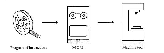
Figure 1.1
When considering the applications and general characteristics of NC machines it is important that two points be kept in mind.
An NC machine tool can do more than it was capable of doing before a control unit was joined to it. There are no new metal removing principles involved. NC machine controls simply position and drive the cutting tools, but the same milling cutters, drills, taps and other tools still perform the cutting operations. cutting speeds, feeds, and tooling principles must be adhered to.
Contrary to what some people think, numerical control machines can not initiate anything on their own. The machine accepts and responds to commands from the control unit. Even the control unit cannot think, judge or reason. Without some input medium, ego punched tape or direct computer link, the machine and control unit will do nothing.
CNC stands for Computer Numerical Control. It is a N.C system in which a dedicated stored program computer is used to perform basic control functions.
The functions of CNC controllers are:
The interpretation of program commands by a machine control unit and its conversion of those commands into machine motion is complex.
Some of the features and functions are discussed later in this unit, but a simplified diagram of the basic elements of a CNC machine are shown in the schematic below.
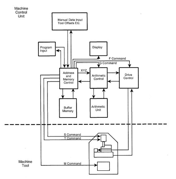
Figure 1.2 Basic elements of an NC system
Most trades persons are usually aware of numerical control metal cutting machines such as CNC mills and CNC lathes. However the scope for NC application extends much further than these applications. Generally NC applications may be considered under the following headings.
Other industries use NC systems for a wide range of activities such as:
Within the machining category, NC machine tools are appropriate for certain jobs and inappropriate for others. Following are the general characteristics in metal machining for which numerical control would be most appropriate.
It has been estimated that a large proportion of manufactured parts are produced in lot sizes of 50 or fewer. Small lot and batch production jobs represent the ideal situations for the application of NC. This is made possible by the capability to program the NC machine and to save that program for subsequent use in future orders. If the NC programs are long and complicated (complex part geometry, many operations, much metal removed), this makes NC all the more appropriate when compared to manual methods of production. If engineering design changes or shifts in the production schedule are likely, the use of tape control provides the flexibility needed to adapt to these changes. Finally, if quality and inspection are important issues (close tolerances, high part cost, 100% inspection required), NC would be most suitable, owing to its high accuracy and repeatability.
In order to justify that a job be processed by numerical control methods, it is not necessary that the job possess every one of these attributes. However, the more of these attributes that are present, the more likely it is that the part is a good candidate for NC.
The great variety of numerical control applications were introduced in the preceding pages. We also examined the general characteristics of production jobs for which NC seems to be particularly well suited. When properly applied, numerical control provides the user with a significant number of economic advantages.
In this section the advantages and disadvantages of NC are discussed and compared with conventional manual methods of production.
Along with the advantages of NC, there are several features about NC which must be considered as disadvantages.
The term Numerical Control refers to the ‘encoding’ of information in a way so as to drive machine tools and slides. You will understand that, regardless oft heir application, most NC machines have three basic sub units:
On a conventional machine an operator controls these functions and sets or alters them when the operator considers it necessary, the decision resulting from his/her training, skill and experience.
Obviously, the machine settings may differ between operators as will the time taken to read scales, set positions, change tools, alter speeds and feeds, engage drives and set up the work piece etc.
CNC automatic control can be applied to these functions and so result in consistent and reduced machining times through optimised cutting data, fast accurate positioning between cuts and fast automatic tool changing.
Like conventional milling machines a CNC machining centre has three basic axis of motion which are driven by the part program in either a pre-selected feed rate or in rapid traverse which is generally in the range of between 10 to 100 metres/minute. The tool slides can be programmed to move independently or as a combined movement of any two or three axis.
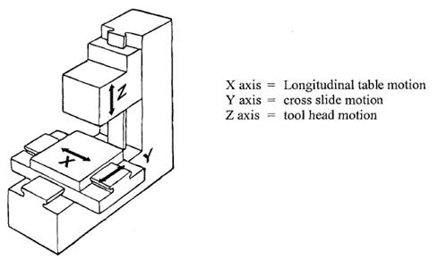
Figure 1.3 Machining centre axes
CNC Machines differ in construction to conventional machines in many areas other than their method of control.
It is essential to accelerate CNC machine slides quickly and also to bring them to rest quickly, so the design must offer as little friction as possible and be rigid without excess weight. If weight and friction can be reduced then so can the size and weight of the drive motor and gearing thereby improving performance.
Slide friction can be reduced with the use of materials offering low co-efficient of friction as well as attention to details such as surface finish and lubrication.
Flat slides also can be 'floated' on a high pressure film of lubrication oil to virtually eliminate normal slide friction. This design is known as hydrostatic sideways, and is complex and costly compared to other systems. Roller or linear ball bearing slides offer low friction also but usually have a trade-off in load capacity.
The main structure of the machine, on which the slides are positioned, must be rigid and stable under conditions such as:
Because component sizes are produced by machine motions that are controlled by unchanging numeric data, it is important that the last part produced at the end of the day will not be altered from the first by thermal instabilities.
On conventional machines, sizes and positions are controlled manually, and it is quite usual for an operator to be constantly altering positions during the machining operations or throughout the day, so thermal stability is not as critical as for CNC machines.
Thermal instability falls into three basic groups:
In the first, the greatest source of heat is from the spindle or geared head, but localised heating of slides and lead screws as well as heat transmitted from drive motors can also affect accuracy. Therefore, the machine tool manufacturer must take thermal effects into consideration at the design stage.
Machining processes can result in a great deal of heat. For example, heavy cutting of large work pieces on milling machines can result in heat being conducted readily into the machine table and slides.
Machines must be sited away from or screened from sources of heat such as afternoon sun through a window, heaters, hydraulic power packs, ovens etc.
Remember a temperature difference of only 1°C over 1000 mm can cause an error of 0.01 mm which may be within the required machine accuracy, but outside the tolerance for the job.
It is usual to build conventional machines from cast iron -a material that offers rigidity and vibration damping, however for a given weight a fabricated (welded) steel structure offers greater rigidity and strength, and it is this construction method that is commonly used for CNC machines.
CNC machines using chip producing machining methods also commonly have tool holding and automatic changing devices in order to maximise production by reducing tool changing times to a few seconds at most.
The CNC Machine Control Unit (MCU) has to read and decode the part program, and to provide the decoded instructions to the control loops of the machine axes of motion, and to control the machine tool operations.
The main grouping of parts of a control could be considered as:
This is the human interface that allows various modes of machine or control operation to be initiated, from switching on and homing, to program loading and editing, to setting work positions and tool offsets, manually controlled movements and commencing the automatic cycling of a program. Information about machine status and condition is available to the operator via VDU screens, gauges, meters, indicator lights and readouts.
A typical control panel is shown on the Sinumerik 820 Machine Control Unit. This panel divides into two broad functional areas.
This part of the control panel allows the operator to communicate with the program and any supporting software which is part of the Read Only Memory (ROM). This interface also has ‘Keyboard’ facilities which allows for Manual Data Input as well as editing and validation of programs. The units video monitor provides a visual display of the programs either as readable data or animated graphics.
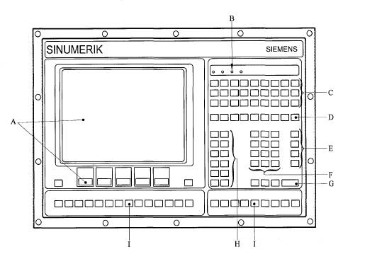
Figure 1.4 CNC machine control panel
A. Graphics display with softkey input
B. Display panel
C. Address keys
D. Symbol keys
E. Calculation keys
F. Numerical keys
H. Control keys
I. User defined keys
Apart from such basic controls as stop and start, this aspect of the control panel also provides the means of manual control and program over-ride. This manual control is needed for tasks such as setting zero and tool offsets.
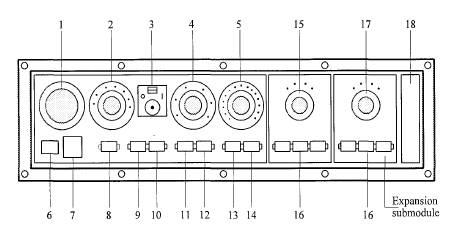
Figure 1.5 CNC control interface
1. Emergency stop button |
2. Mode selection switch |
3. Single block switch |
4. Spindle over-ride switch |
5. Feed rate over-ride switch |
6. Machine ON switch |
7. Key locked switch |
8. RESET key |
9. NC stop key |
10. NC start key |
11. Spindle stop key |
12. Spindle start key |
13. Feed stop key |
14. Feed start key |
15. Axis selector switch |
16. Direction key |
17. Aux. axis key |
18. Serial interface |
The tape reader, where fitted, is used to transfer the program information contained on a program tape into the control unit. Most tape readers are of the photo-electric type which offer high speed reading with reliability and accuracy providing the tape is in good condition and the reader is kept clean and free of paper dust particles.
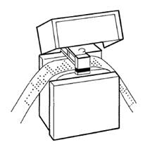
Figure 1.6 Tape reader
The tape reader reads NC tape coding and passes the information to registers within the machine control unit (MCU). The coded information then passes electronically to the machine tool where appropriate action or movement occurs.
Punched tape may be read:
The processes within a control are the electronic circuits that permit conversion ofpart program data into the machine motions and they may be classified into two main sections:
The prime function of a data processing unit is to receive and decode the commands detailed in a part program. Additional functions include:
This part of the control unit circuitry receives the decoded signals from the data processing unit and in tum operates the slide drives. The axis control processor also receives and interprets feed back signals on the actual position and velocity of each action.
The axis control processor consists of the following circuits:
Source: http://lrr.cli.det.nsw.edu.au/LRRDownloads/12571/1/12571.doc
Web site to visit: http://lrr.cli.det.nsw.edu.au
Author of the text: indicated on the source document of the above text
If you are the author of the text above and you not agree to share your knowledge for teaching, research, scholarship (for fair use as indicated in the United States copyrigh low) please send us an e-mail and we will remove your text quickly. Fair use is a limitation and exception to the exclusive right granted by copyright law to the author of a creative work. In United States copyright law, fair use is a doctrine that permits limited use of copyrighted material without acquiring permission from the rights holders. Examples of fair use include commentary, search engines, criticism, news reporting, research, teaching, library archiving and scholarship. It provides for the legal, unlicensed citation or incorporation of copyrighted material in another author's work under a four-factor balancing test. (source: http://en.wikipedia.org/wiki/Fair_use)
The information of medicine and health contained in the site are of a general nature and purpose which is purely informative and for this reason may not replace in any case, the council of a doctor or a qualified entity legally to the profession.
The texts are the property of their respective authors and we thank them for giving us the opportunity to share for free to students, teachers and users of the Web their texts will used only for illustrative educational and scientific purposes only.
All the information in our site are given for nonprofit educational purposes