Electrical Equipment: Any item used for such purposes as generation, conversion, transmission, distribution or utilisation of electrical energy, such as machines transformers. apparatus, measuring instruments, protective devices, equipment for wiring systems and appliances.
Electrical Installation: An assembly of associated electrical equipment, to fulfil a specific purpose or purposes and having co-ordinated characteristics.
Accessory: A device, other than current-using equipment, associated with such equipment or with the wiring of an installation.
Ambient Temperature: The temperature of the air or other medium where the equipment is to be used.
Appliance: Any device that utilises electricity for a particular purpose, excluding a luminaire or an independent motor.
Insulation: Non-conducting material enclosing, surrounding or supporting a live part.
Insulated conductor: A conductor having only basic protection against shock, consisting of a covering of insulation.
Cable: An insulated conductor with an outer protective covering against external influences.
External Influences: Any influence external to an installation which affects the design or safety of the installation.
Fixed Wiring or Cable: Wiring or cable mounted on a fixed support so that its position does not change.
Flexible Wiring or Cable: Wiring or cable that may be moved in normal service between its points of termination.
Conduit: A system of tubing intended to enclose cables and wires in order to protect them from mechanical damage, and to allow them to be drawn-in and withdrawn.
Cable Trunking System: A factory-made system for enclosing cables and insulated wires, normally of rectangular cross-section, one side of which can be removed, and forming part of the wiring system.
Neutral Conductor ( symbol N ): A conductor connected to the neutral point of a system for the purpose of transmitting electrical energy.
Phase Conductor: A conductor of an AC system, other than a neutral conductor, intended for the transmission of electrical energy ( also called “line conductor” ).
Cable Coupler: A means enabling the connection, at will, of two flexible cables. It consists of a connector and a plug.
Enclosure: A part providing an appropriate degree of protection of equipment against certain external influences and, a defined degree of protection against direct contact with live parts.
Building Void: A space within the structure or components of a building, which may be accessible at certain points.
Common Electrical Conducting Materials
Material Properties Applications
Silver Best conductor material. Used to plate contacts to
Expensive. ensure good electrical contact.
Soft and easily shaped.
Copper Very good conductor. Used extensively as a
Soft and easily drawn into wires. conductor material in cables
Easy to joint and solder. and busbars.
Good conductor of heat
Gold Good conductor. Used to plate contacts.
Does not corrode.
Expensive.
Aluminium Good conductor. Used to manufacture
Low cost and weight. larger cables and busbars.
Soft and easily shaped. Overhead cables with steel core.
Not as flexible as copper.
Corrodes.
Tungsten Easily drawn into very fine wires. Lamp filaments.
Very high melting point.
Brass An alloy of copper and zinc. Used to manufacture cable
Easily machined. glands, terminals, plug pins,
Resists corrosion. some conduit fittings, nuts,
bolts and washers.
Steel Reasonably easy to shape. Used to manufacture
conduit, trunking, tray,
enclosures and various fittings.
May be galvanised.
Tin Resists corrosion. Used to manufacture solder.
Coating on copper cables
insulated with vulcanised rubber.
Lead Does not corrode. Used to manufacture solder,
Easily shaped. sheaths of cables, plates
in lead-acid cells.
Mercury Liquid at normal temperature. Used in tilt switches.
Nichrome Nichrome is an alloy of Used to manufacture heating
nickel and chromium elements.
Hard and resists corrosion
Carbon Good conductor. Brushes for electrical machines.
Hard wearing - self lubricating
- negative temperature co-efficient
of resistance.
Common Electrical Insulating Materials
Material Properties Applications
PVC Weather resistant. Cable insulation.
( poly-vinyl ( Standard grade 0 to 70oC ) Cable sheaths.
-chloride ) Flexible
( Arctic grade -20 to +70oC )
Affected by contact with wet
creosote or certain thermal insulating
materials, such as expanded
polystyrene.
Emits smoke and fumes when burning.
Crosslinked Emits little smoke or fumes Cable insulation and sheath.
Polyethylene when burning.
( XLPE ) Temp. range (-40 to +90oC )
Rubber Flexible. Cable insulation and sheath.
Ages. Moulded plug tops and extension
Absorbs solvents and swells. sockets.
Temp. range (-25 to +65oC ).
High temp. type up to 85oC.
Silicone Rubber
Flexible.
Conductor insulation for
Temp. up to 145oC High temp. areas,
( Special type -60 to +260oC ). e.g. cooker internal wiring.
( 300oC for short durations ). Insulation sleeving.
Plastic Relatively cheap. Plugs, sockets, switches,
Not too brittle. fuse carriers, fuse bases,
Can be moulded into conduits, trunking and
intricate shapes. enclosures.
Porcelain Hard and brittle. Fuse carriers and bases.
Easily cleaned. Overhead line insulators.
High temp. range. High temp. connectors.
Glass Rigid and brittle. Overhead line insulators.
Easily cleaned.
Glass Fibre Reasonably flexible. Conductor insulation in high
Temp. up to 170oC. temp. areas e.g. ovens.
Asbestos Reasonably flexible. Conductor insulation in high
temp. areas. ( Old types ).
Mica High temp. range. Toaster elements.
Brittle. Motor commutator insulation.
Magnesium In powder form. Insulation in mineral insulated
Oxide Requires containing sheath cable ( MIMS ). ( PYRO ).
High temp. range ( 145oC ). Insulation in sheathed elements
Hygroscopic ( absorbs moisture ). for kettles, cookers,
Good conductor of heat immersion heaters.
Butyl Rubber Tough. Extension leads in
Remains flexible from arduous conditions.
-40oC to +85oC.
Cables and Flexible Cords
Cable Definition
One or more conductors provided with insulation. The insulated conductor (s) may be provided with an overall covering to give mechanical protection.
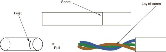
Construction: A cable consists of three parts. See Figure 1:
|
Figure 1
The most common conductor material used is copper. Aluminium is used for larger cables and its use is not permitted in domestic installations.
The most common insulation used is PVC. Other materials are used as insulation depending on what the cable is being used for and where it is being installed.
The most common mechanical protection used is PVC. Further protection is provided by installing cables in locations where they are unlikely to be damaged. Where this is not possible, cables must be installed in conduit, trunking or ducting. Otherwise a suitably armoured cable must be used. When cables are installed in conduit or trunking they need not have any other form of mechanical protection. The conduit or trunking is deemed to be its mechanical protection.
Cables are manufactured in a range of common sizes. These are decided by the Cross Sectional Area ( CSA ) of the conductor, which is specified in square milli-metres ( mm2 ).
The following is a list of the standard sizes used in domestic installations.
Cross Sectional Area
Cross sectional area is the surface area of a section of conductor.
1.5 mm2 – 2.5 mm2 – 4 mm2 – 6 mm2 – 10 mm2 – 16 mm2
The cable insulation is colour coded as follows:
Phase ( Live ) – Brown
Neutral – Blue
Earth – Green / Yellow
In the cable most commonly used for domestic installations, there is a bare earth conductor and this must be terminated using Green / Yellow sleeving.
Cables are manufactured with solid, stranded or flexible cores.
Solid cores are used for the small cable sizes where the wiring is fixed.
Stranded cores are used for the larger cable sizes and where more flexibility is required, e.g. where cables are installed in conduit or trunking systems.
The number of strands is normally 7, 19 or 27 per core.
Flexible cores are used where extra flexibility is required,
e.g. pendants, immersion heaters and also leads for portable and hand held equipment. The number of strands is normally 16, 24, 32, 36, 40 or 50 per core.
These flexible cores when used as leads for portable and hand held equipment must be provided with an overall covering for mechanical protection. This unit is referred to as a flexible cord.
Flexible Cord Definition
“A flexible cable in which the CSA of the conductors does not exceed 4 mm2.”
Flexible cords are manufactured in standard sizes as follows:
0.5 mm2 – 0.75 mm2 – 1.0 mm2 – 1.25 mm2 – 1.5 mm2 – 2.5 mm2 – 4 mm2
Larger flexible conductors are known as flexible cables.
Single Core Circular Cables
Solid or stranded copper conductor with PVC insulation.
e.g. 1.5 mm2 PVC Brown. See Figure 2.
Applications: Installations where drawn into conduit or trunking.
Sizes: 1.5 2.5 4 6 10 16 mm2
|
Figure 2.
Solid or stranded copper conductor with PVC insulation surrounded by a PVC sheath.
e.g. 1.5 mm2 PVC / PVC Blue. See Figure 3.
Applications: Used in domestic installations and for clipping on the surface where little risk of mechanical damage exists.
Sizes: 1.5 2.5 4 6 10 16 mm2
|
Single Core Cables
Solid or stranded copper conductor with PVC insulation surrounded by a PVC sheath.
e.g. 1.5 mm2 PVC / PVC Brown and Earth. See Figure 4.
Applications: Used for lighting circuits in domestic installations and for clipping on the surface where little risk of mechanical damage exists.
Size: 1.5 mm2
|
Multicore Flat Cables
Two copper conductors, PVC insulated, laid parallel and surrounded by PVC sheath to give a flat finish. An uninsulated protective conductor is laid in the centre.
e.g. 1.5 mm2 Twin Brown / Blue and Earth. See Figure 5.
Applications: As for single core PVC / PVC, especially suited to three-plate ceiling rose method of wiring. Also used for wiring socket outlets etc.
Sizes: 1.5 2.5 4 6 10 16 mm2.
|
Twin core, solid conductors, with PVC insulation. See Figure 6.
Applications: Bell and indicator systems.
( Suitable for up to 50 Volts. )
|
Figure 6.
Round Flexible Cords
PVC insulated flexible copper conductor with PVC sheath forming a round cord.
Available in two, three, four and five cores.
e.g. 2 x 0.75 mm2, PVC circular flex. See Figure 7.
Applications: General-purpose flexible cord for pendants, portable tools and appliances. Should not be used where sheath can come into contact with hot surfaces.
Sizes: 0.5 0.75 1.0 1.25 1.5 2.5 4 mm2.
|
Figure 7
The insulation and sheathing is made from heat resistant PVC and is available in two, three and four cores, e.g. 3 x 1.5 mm2, heat resistant flex. See Figure 8.
Applications: Suitable for use in temperatures up to 85oC. e.g. immersion heaters.
Sizes: 0.5 0.75 1.0 1.25 1.5 2.5 4 mm2.
|
Figure 8
Terminals, Clamps and Lugs
There are a wide variety of conductor terminals. Typical types are as shown in Figure 9.
|
Figure 9
Use of Hand Tools
Electricians Pliers
Long Nose Pliers
Side Cutters
This is used to cut the larger size cables, cut mini trunking and cut out openings in surface boxes for cable entry.
Pad Saw
This is used to cut holes in plasterboard to enable the installation of drylining boxes.
Bradawl
This is used to make holes in timber to aid accurate positioning and driving of woodscrews
Knife
Screwdrivers
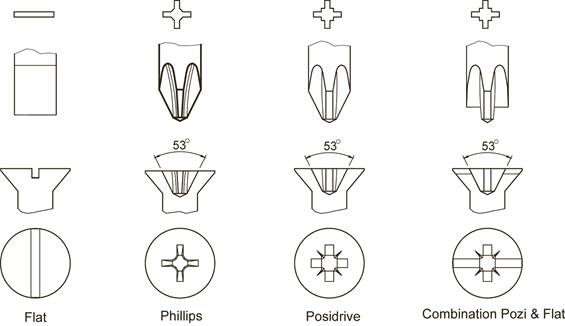
Flat Blade Screwdrivers
Pozidrive Screwdrivers
Marking Out
When installing electrical equipment and fittings into a building the electrician must decide where and how to fix to the floor, wall or ceiling.
The electrician may have working drawings available, indicating where the various fittings such as lights, switches, power points and / or appliances are to be installed. Symbols are used in the drawing legend to indicate the type of fixture and their exact location in the building.
Dimensions as to the height of switch drops and height of fixtures above the finished floor level are usually included.
With or without the information contained in working drawings the electrician has to translate installation plans into action. The first action is to mark out the exact location for the fixtures to be installed and also the route, which the cables will follow.
Marking a Vertical Line ( Plumb Line )
Plumb lines, sometimes called “plumb bobs” are used to establish VERTICAL LINES.
The plumb bob consists of a balanced weight attached through its centre to one end of a piece of twine. It may be held or suspended from a point above. When stable, it will indicate a true vertical line.
See Figure 25.
Two pencil marks to correspond with the line of the twine are drawn, one at each end. Joining these two marks will provide a true vertical line.

Figure 25.
Chalk Lines
Chalk lines are normally 3-5 metre lengths of twine impregnated with fine chalk powder. With purpose made chalk lines, chalk is applied to the twine as it is played out from the spool. A chalk line is so shaped that it can be used as a plumb bob.
To mark a chalk line, use the free hand to lift the tautly held string away from the wall and then release it. The string will spring back and deposit a line of chalk on the surface of the wall. See Figure 27. For long runs, fix the line at both ends and pluck in a similar manner near the centre.
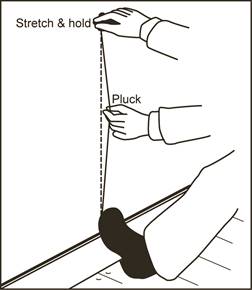
Figure 27.
The most common tool used to produce a horizontal line is a spirit level.
It consists of a straight edge, generally made of aluminium. A tough glass tube is fixed into the middle and both ends. These tubes are almost completely filled with liquid. Only a small air bubble remains. When the air bubble is located centrally between two markings on the centre tube, the spirit level is horizontal and a pencil line can be drawn. A spirit level may also be used to mark vertical lines. The tubes at either end are used for this purpose. Some models facilitate the marking of a 45° line using one end. Sizes vary from about 250mm to 2 metres long.
A level should be treated with care. For accurate marking, ensure that the bubble is equally spaced between the two lines on the glass tube.
See figure 28
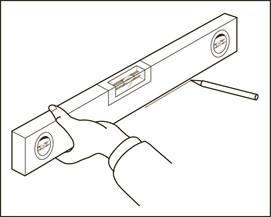
Figure 28.
Measuring Off
Horizontal lines can be drawn by measuring off from a common base. On walls this base could be either the floor, top of the skirting board or a ceiling surface provided these are reasonably level and even. Identical measurements are taken a short distance out from the corner of the wall, floor or ceiling and marked out. For long runs, intermediate points may also have to be marked out.
A chalk line is stretched over these marks for the required distance and ‘plucked’ to mark a line. Alternatively a long straight edge could be utilised.
The measuring off method is used in many situations where installations are made parallel to existing features, such as doorframes, architraves, skirting boards, ceiling cornices, rather than at the ‘true’ vertical or horizontal.
Never mark or draw, more lines than are absolutely necessary particularly on decorated surfaces. If you must mark the walls use chalk lines ( white ), which can be easily erased later.
Marking Out on a Ceiling
Marking out directly onto a ceiling is difficult without assistance. An alternative method is to mark out on the floor and transfer the points to the ceiling by use of a plumb line.
Figures 29 and 30 illustrate this process.
Fixing Devices
There is a wide range of fixing devices in use in the electrical trade. They can be classified according to their use with particular building materials such as wood, concrete, metal, plasterboard etc. The following are examples of some types of woodscrews which are widely available.
Figure 31 illustrates a slotted countersunk head woodscrew. This screw is used to fix items which have countersunk fixing holes. The screw head finishes flush with the surface of the work.
 |
Figure 31.
Figure 32 illustrates a pozidrive countersunk head woodscrew. Its application is the same as the previous type but it has the advantage that the screwdriver used is easier to locate and less likely to slip while in use.
 |
Figure 32.
Figure 33 illustrates a round head woodscrew which is used to fix items which do not have countersunk or counterbored holes, e.g. plastic or steel trunking. The reason for this is that the screw has no sharp edges which might damage cable insulation. This screw also provides a more decorative finish where fixing screws remain visible.
 |
Figure 33.
All of these woodscrews are available in a range of sizes. They are sized according to their length, and diameter of the thread, in millimetres. A screw having a diameter of 4mm and a length of 25mm will be designated as an M4 x 25. The type of head incorporated will also be stated.
Machine Thread Screws
Machine thread screws are used to fix switches, sockets, ceiling roses etc., to their respective boxes. The following are examples of the more common types encountered in the electrical trade.
Figure 34 illustrates a slotted countersunk head machine thread screw. It is used to fix ceiling roses and battenholders to boxes which have machine thread inserts. The screw diameter in common use is 4mm. They are available in various length such as 6mm, 12mm, 16mm, 20mm, 25mm, 30mm and 40mm. They are manufactured from brass and have a thread pitch of 0.7mm.
 |
Figure 34.
Figure 35 illustrates a pan head screw. It is used to fix items similar to those mentioned previously which do not have countersunk fixing holes. Pan head screws provide a neat finish where fixing screws remain visible.
 |
Figure 35.
Figure 36 illustrates a raised countersunk head screw. It is used to fix switches, sockets etc., to boxes which have machine thread inserts. The diameter in common use is 3.5mm. They are available in 20mm, 25mm, 60mm,75mm and 100mm lengths. They are generally brass with a nickel plated finish and have a thread pitch of 0.6mm.
 |
Figure 36.
Method of Fixing into Wood
First decide on the position of fixtures. Then take measurements off the walls, ceiling or floor. Use the same base line (datum line) each time. For repetitive fixing, a measuring rod may be more efficient. Using the fixture itself, or a template, clearly mark out the position of the holes using a pencil or a bradawl
Make a hole in the wood, for one woodscrew, using the bradawl. The hole should be about half the depth by which the woodscrew must enter the wood. As a general guide the woodscrew should enter the wood a distance equal to 5 times its thread diameter. Select the correct type and size of woodscrew. Note the surface finish on the fixture at the fixing point. Where a recess is provided, use a countersunk screw, if not use a round head screw. Check the diameter of the hole in the fixture and select a screw having a diameter equal to or slightly less than this. Drive the woodscrew into the prepared hole (preferably an uppermost hole) and allow the fixture to hang from this screw. The fixture can now be aligned accurately. Each remaining hole can be checked and started using the bradawl. The screws can be inserted and driven home. Finally tighten the first screw and check that the fixture is secure.
N.B. Do not overtighten screws particularly when securing hard plastics as these may crack easily.
When driving screws into hard woods it is advisable to drill a pilot hole which should be 2 mm less than the diameter of the screw thread.
Method of Fixing into Partition Walls
A fair proportion of electrical installation work involves fixing items to partition walls of various types. These may be plasterboard or timber walls for example. It is essential to know what fixing methods may be used.
Spring Toggle Fixings
The spring toggle consists of a plated steel, spring actuated toggle bar, pivoted on a swivel nut. When the nut has been run on to the end of the screw, the toggle is pushed through the fixing hole into the cavity whereupon it springs open and is then pulled back against the material to tighten the screw. The design of this fixing causes the load to be spread over a wide area.
The spring toggle is ideal for making fixings to cavity walls and ceilings where only one side of the material is accessible. It is especially effective when fixing to plasterboard and similar materials of low structural strength where, by embracing a comparatively wide area, reasonable loads can be supported.
N.B. If the screw of a spring toggle fixing is removed completely, the toggle will be lost inside the cavity.
Method of use:
Rawlnut Multipurpose Fixing
The rawlnut fixing consists of a tough natural rubber sleeve with a non-ferrous nut bonded in one end, and a moulded external flange at the other. When the screw is tightened, the rubber sleeve compresses into a strong rivet fixing on the reverse side of the partition.
The rawlnut is suitable for securing fixtures to plasterboard, plastics, sheet metal, concrete and glass, to name but a few. It provides a fixing which is corrosion resistant, waterproof, vibration proof and electrically insulated.
N.B. When the screw is removed, the sleeve will remain in position and can be re-used.
Method of Use.
Interset Cavity Fixing
The interset is a plated steel cavity fixing, having one end internally threaded to receive a fixing screw. The other end has an external flange which is provided with teeth. These teeth penetrate the material and so prevent rotation. Fixing is achieved by deforming the legs into a large load bearing surface against the sheet material.The interset is suitable for securing fixtures to plasterboard and other similar materials. It provides a solid fixing and can achieve the maximum load that the material can support.
N.B. If the screw is removed completely the interset will remain in position and can be reused.
Method of use.
N.B. A special interset fixing tool is available and would be an advantage in handling a large number of fixings.
Plasterboard Anchor
Figure 41 illustrates a zinc alloy plasterboard anchor which is quick and easy to install. One end is pointed to enable it to drill a pilot hole in the plasterboard. The other end consists of a flange which can be driven home using a pozidrive screwdriver. These are also available in plastic.
The plasterboard anchor features a deep thread form which ensures a strong engagement in the plasterboard. See Figure 42.
This fixing is manufactured specifically for use on plasterboard surfaces. Each fixing is supplied with its own fixing screw. The fixing remains in place in the plasterboard if the fixing screw is removed.
Method of use.
Surface Installation of PVC / PVC Cables
Cable Clips
Clips are manufactured to suit the size and shape of the various cables. Oval clips are sized according to the thickness and width of the cable for which they are suitable e.g. a 5 x 8 clip suits a 1.5 Twin or a Twin + Earth cable which measures approximately 5 mm x 8 mm. Clips are expandable to some degree. Circular clips are sized in a similar manner e.g. a 10 - 14 clip suits any cable having a diameter between 10 mm and 14mm.
Clipping of PVC / PVC Cables
PVC / PVC cables may be installed directly on a surface or in a void, where there is little risk of mechanical damage. The ambient temperature range in which they may be installed is from 0oC to 60oC. PVC / PVC cable is used in domestic and light commercial installations.
These cables are fixed in position using hardened PVC clips which incorporate a nail suitable for driving directly into most surfaces. If the surface is too hard ( e.g. mass concrete ) a hole should be made using a hammer action drill and a masonry drill bit. A clip plug is then inserted into the hole and the clip nail may then be driven home. The section of the clip incorporating the nail should be placed underneath the cable to provide proper support.
The spacing between clips should be such that the cable is adequately and neatly supported in a straight line. For horizontal runs, the cable should not sag between clips.
Where cable runs change in direction, it will be necessary to bend or offset the cable. This must be done in such a way as to avoid damaging any part of the cable. For PVC / PVC cables a suitable minimum internal radius for bends may be found by multiplying the cable external diameter by a factor of 3.
For appearance sake, clips should be equally spaced on either side of a bend or fixture. Clips should be equally spaced along a straight run.
Refer to Figure 44. Ensure a neat appearance by pressing the cable flat and stretching it, between clips. Straighten the cable by running the thumb along it as shown. It helps if you avoid kinking the cable when uncoiling.
Refer to Figure 45. Running the palm of the hand along the cable will also help in forming it.
Refer to Figure 46. The previous steps should be repeated after the fixing of each clip.
Where a bend has to be formed, use the fingers and thumb as shown in Figure 47. Ensure that the bend is uniform and not too sharp and also that the clips are evenly spaced either side of the bend.
Guidelines for clipping 1.5mm2 Twin and Earth Cable
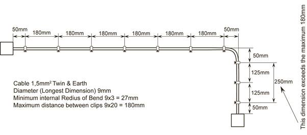
Figure 48.
Cable Mechanical Protection
The PVC sheath must enter into any enclosure to protect the conductor insulation from damage. Once inside the enclosure, the sheath can be removed because the enclosure now provides mechanical protection for the cable insulation.
There should be sufficient cable slack allowed in an enclosure to facilitate the termination and remaking of cables. This will also facilitate any alterations to the circuit or replacement of accessories. See Figure 49.
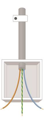
Figure 49.
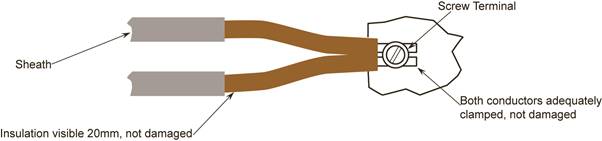
Terminating Techniques
Screw Terminal
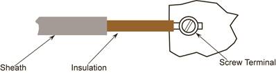
If the conductor is small in relation to the terminal, the conductor must be doubled back fully, neatly on itself. See Figure 52 for a correct termination.
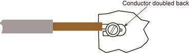
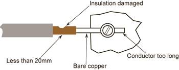
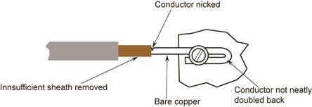
Figure 53 shows an incorrect termination.
Screw Head and Nut and Washer Terminals
Clamp Type Terminal
Criteria for Good Terminations
Dangers of Loose Connections
Role of Electrical Bodies
International Electro-technical Commission ( IEC )
European Committee for Electro-technical Standardisation
The Electro-Technical Council of Ireland ( ETCI )
The ETCI, is a voluntary body of twenty two organisations representative of all aspects of electro-technology in this country. Formally constituted in 1972, the Council is the national body responsible for the harmonisation of standards in the electrotechnical field, in collaboration with the National Standards Authority of Ireland ( NSAI ).
Register of Electrical Contractors of Ireland ( RECI )
Electrical Contractors Safety and Standards Association Ltd
Electricity Supply Board ( ESB )
Health and Safety Authority ( HSA )
National Standards Authority of Ireland ( NSAI )
Source: http://local.ecollege.ie/Content/APPRENTICE/liu/electrical_notes/LL221.doc
Web site to visit: http://local.ecollege.ie
Author of the text: indicated on the source document of the above text
If you are the author of the text above and you not agree to share your knowledge for teaching, research, scholarship (for fair use as indicated in the United States copyrigh low) please send us an e-mail and we will remove your text quickly. Fair use is a limitation and exception to the exclusive right granted by copyright law to the author of a creative work. In United States copyright law, fair use is a doctrine that permits limited use of copyrighted material without acquiring permission from the rights holders. Examples of fair use include commentary, search engines, criticism, news reporting, research, teaching, library archiving and scholarship. It provides for the legal, unlicensed citation or incorporation of copyrighted material in another author's work under a four-factor balancing test. (source: http://en.wikipedia.org/wiki/Fair_use)
The information of medicine and health contained in the site are of a general nature and purpose which is purely informative and for this reason may not replace in any case, the council of a doctor or a qualified entity legally to the profession.
The texts are the property of their respective authors and we thank them for giving us the opportunity to share for free to students, teachers and users of the Web their texts will used only for illustrative educational and scientific purposes only.
All the information in our site are given for nonprofit educational purposes