
Performance Trends for Positive Displacement Compressors
Positive displacement compressors use a piston-cylinder combination to decrease the refrigerant volume to produce a corresponding pressure rise. Each of the positive displacement compressor types (reciprocating, rotary, scroll, and screw) uses a different mechanism but the basic processes are similar. The processes for the reciprocating compressor are relatively easy to visualize and provide a set of relations that are useful to explain the observed performance of positive displacement compressors. The effect of operating conditions is discussed in this section.
A schematic of a reciprocating compressor, along with a pressure-volume diagram for the processes, is shown in Figure 6.1. The compressor suction state, which is the initial state for compression, is labeled state 1, and the compressor discharge state, which is the outlet state for the compression process, is labeled state 2. The states inside the cylinder corresponding to the different piston positions are labeled a, b, c and d.
The compression process starts when the cylinder is filled with refrigerant, essentially at the pressure of the evaporator (state a). The piston moves to the left, compressing the refrigerant. Typically the inlet and exhaust valves are reed or ring valves that are forced open or closed depending on the pressure difference across them. Thus, as the pressure starts to build up the inlet valve closes automatically, but the pressure is too low to open the discharge valve. As the piston continues to move, the cylinder volume decreases and the pressure rises. When the pressure inside the cylinder exceeds that of the condenser (at state b) the discharge valve is forced open and refrigerant flows into the condenser. The pressure inside the cylinder slightly exceeds that of the condenser, depending on the pressure drop across the discharge valve. At the top of the piston stroke (at state c) a small amount of refrigerant remains in the clearance volume between the top of the piston and the cylinder head. When the piston starts to move to the right the pressure drops and the discharge valve closes. As the piston moves further to the right, the vapor in the clearance volume expands and the pressure decreases. When the pressure inside the cylinder is less than that of the evaporator (at state d) the inlet valve opens and a new charge of refrigerant begins to enter the cylinder. Depending on the pressure drop across the inlet valve, the pressure at states d and a is slightly below that of the evaporator. Refrigerant continues to flow into the cylinder as the piston moves further to the right. When the piston reaches the bottom of its stroke (state a), the inlet valve closes and compression begins again.
The refrigerant mass flow rate through the compressor is the product of the mass induced per cycle and the cyclic speed of the compressor. The mass inside the cylinder depends upon the volume that is filled each stroke, which depends on the evaporator and condenser pressures, and on the inlet refrigerant specific volume, which depends on the evaporator pressure. The compressor power required to create the flow depends on the mass flow rate and pressure difference between the condenser and the evaporator. Analyzing these processes inside the cylinder allows the development of relations for refrigerant flow rate and compressor power that give insight into the performance of a refrigeration system.
The refrigerant mass that enters the cylinder each stroke is given by the volume that is filled divided by the specific volume of the refrigerant at suction conditions. Pressure drops across the inlet valve and heat transfer from the relatively warm compressor shell to the incoming gas increase the specific volume over that in the evaporator. The volume that is filled is that between states a and d as shown on Figure 6.1. The mass flow rate is the product of the mass induced and the cyclic speed of the compressor (i.e., number of inlet stokes per unit time), or
![]() (6.1)
(6.1)
The volume at state d is not a fixed value but depends on the pressure levels in the condenser and evaporator. As seen from Figure 6.1, if the evaporator pressure were increased then the volume at state d would be smaller. It is convenient to introduce the displacement volume, which is the total volume displaced by the piston each stroke, and then to use a volumetric efficiency to specify the volume that is actually displaced by each stroke. The displacement volume is the difference between the volume at bottom and top dead center, or:
![]() (6.2)
(6.2)
The volumetric efficiency is defined as the volume flow rate over the displacement volume rate. Volume flow rates are used rather than mass flow rates to more readily account for the effects of pressure and temperature on the performance.
![]() (6.3)
(6.3)
In terms of the volumes defined in Figure 6.1, the volumetric efficiency is
![]() (6.4)
(6.4)
It is also convenient to define the clearance volume fraction, which is the clearance volume relative to the displacement volume. The clearance volume is the volume of the cylinder when the piston is at top dead center.
![]() (6.5)
(6.5)
Substituting equation 6.5 into equation 6.4 allows the volumetric efficiency to be expressed as:
![]() (6.6)
(6.6)
Other volumetric efficiencies are sometimes defined, and the relation given by equation 6.6 is termed the clearance volume efficiency.
In order to evaluate the clearance volumetric efficiency for a given operating condition, the volume of the cylinder when fluid enters from the evaporator, Vd, must, be known. This volume results from the expansion of the refrigerant contained in the clearance volume and is a function of both evaporator and condenser pressures. It is conventional to assume that the expansion and compression processes are polytropic processes in which the pressure and specific volume of the vapor are related through an expression of the form:
![]() (6.7)
(6.7)
or, specifically for the compression and expansion processes
![]() (6.8)
(6.8)
If the expansion and compression processes were reversible and adiabatic and the refrigerant behaved as an ideal gas, the polytropic exponent n for both processes would be equal to the isentropic exponent k, which is the ratio of specific heats. For halocarbons, the isentropic exponent is in the range of 1.1 to 1.3. Because there is heat transfer between the vapor and the cylinder walls during the piston motion, the processes are not adiabatic. Fluid turbulence and friction as the flow enters the cylinder create irreversibilities. Even so, the assumption that the processes are isentropic is reasonably accurate and will be used in estimating the volumetric efficiency and its effect on compressor performance.
The expression for the volumetric efficiency, equation 6.6, can be written in terms of the condenser and evaporator pressures using the relations for polytropic processes, equation 6.8. The mass of refrigerant is the same at states c and d, and the ratio of the total volume at d to that at c thus equals the ratio of specific volumes. To develop a relation for the clearance volumetric efficiency, it is assumed that there are no pressure drops across the inlet and discharge valves so that the pressure at state d is the same as that in the evaporator, pe. Similarly, it is assumed that there are no pressure drops across the discharge valve so that the pressure at state c equals that of the condenser, pc. The volume ratio can then be expressed in terms of the pressure ratio as
 (6.9)
(6.9)
By combining equations 6.6 and 6.9, the clearance volumetric efficiency can be expressed as:
 (6.10)
The refrigerant mass flow rate can be expressed in terms of the volumetric efficiency, the displacement volume, the suction specific volume, and the cyclic rate of the compressor by combining Equations 6.1, 6.2, and 6.4.
![]() (6.11)
(6.11)
Using the expression for the clearance volumetric efficiency (equation 6.10), the mass flow rate can be expressed as:
 (6.12)
Equation 6.12 shows that the mass flow rate decreases as evaporator pressure decreases due to two effects. First, the entering specific volume is greater at lower evaporator pressures, and, second, the clearance volumetric efficiency is lower for lower evaporator pressures due to greater expansion of the gases in the clearance volume. The clearance volumetric efficiency is also lower for higher discharge pressures.
The actual volumetric efficiency is usually lower than the clearance volume efficiency given by equation 6.10 for a number of reasons. As the vapor in the clearance volume expands during the expansion stroke, heat is transferred from the hot cylinder walls to the refrigerant. At the end of expansion the volume occupied by the vapor is then greater than that determined from the polytropic process and thus less fresh vapor can enter the cylinder. There are also pressure drops when the refrigerant flows across the inlet and exhaust valves. Thus the pressure inside the cylinder at intake is lower than the evaporator pressure and more volume is occupied by the clearance volume vapor, both of which reduce the volume flow rate.
Correspondingly, the pressure inside the cylinder is slightly higher than the condenser pressure at discharge due to pressure drops across the exhaust valve. Thus the mass of vapor left in the clearance volume space is higher than it would be if the pressure were the condenser pressure. Further, there may be some leakage past the piston rings to the lower pressure in the crankcase. As a result of all of these effects, the actual volumetric efficiencies for compressors in operation are typically lower than that estimated from equation 6.10.
The compressor power can be calculated from the work expressions for a closed system, which represents the gas contained in the cylinder after the valves have closed. The power is the difference between the compression and expansion work times the mass flow rate, or:
![]() (6.13)
(6.13)
The integrals in equation 6.13 are evaluated assuming that the compression and expansion processes are polytropic processes given by equation 6.8. The expression for power is then
 (6.14)
where hV is the actual volumetric efficiency, and accounts for irreversibilities that occur due to non-uniform pressures, flow leakages, heat transfer, and pressure drops across valves. There are further irreversibilities associated with the electric motor and mechanical friction in the compressor. It is convenient to account for these effects using a combined motor-compressor efficiency defined as the ratio of the ideal compressor power, equation 6.14, divided by the electric power to the motor.
![]() (6.15)
(6.15)
The clearance volume efficiency and polytropic work relations assume that there are no pressure drops across the valves and that the compression and expansion processes are ideal and polytropic. These relations then give an upper limit for the performance. Example 6.1 illustrates the use of these relations to estimate the performance of an ideal compressor.
"Example 6.1 Determine the clearance volumetric efficiency, mass flow rate, reversible polytropic power requirement (kW), cooling capacity (tons), coefficient of performance and discharge temperature for a refrigeration system with a reciprocating compressor that has a displacement volume of 0.02 ft3, a clearance volume fraction of 0.05, a rotational speed of 1740 rpm. The refrigerant is R-22, and leaves the evaporator at a saturation pressure corresponding to 25 F with 5 F superheat and leaves the condenser as saturated liquid at 120 F. The polytropic exponent for the process is 1.2."
"Problem Specifications"
V_disp = 0.02 “ft3” “Displacement volume”
C = 0.05 “Clearance vol fraction”
N_dot = 1740 “rpm” “Rotational speed”
T_e_sat = 25 “F” “Evaporator sat temp”
T_super = 5 “F” “Superheat”
T_c = 120 “F” “Condenser sat temp”
n=1.2 “Polytropic exponent”
"Determine the inlet state of the refrigerant entering the compressor, which is the exit state from the evaporator."
p_in = pressure(R22,T=T_e_sat, x=1) “psia” “Inlet pressure”
T_in = T_e_sat + T_super “F” “Inlet temperature”
v_in = volume(R22, T = T_in, p=p_in) “ft3/lbm” “Inlet specific volume”
"Determine the discharge pressure from the compressor"
p_c = pressure(R22, T=T_c, x=1) “psia” “Discharge pressure”
"Determine the clearance volumetric efficiency from equation 6.10 using the clearance volume fraction, the inlet and discharge pressures, and the polytropic exponent"
eta_vol = 1 + C - C*(p_c/p_in)^(1/n) “Clearance volumetric efficiency”
"Determine the mass flow rate from equation 6.11 using the rotational speed, displacement volume, and inlet specific volume."
m_dot = eta_vol*N_dot*V_disp/v_in*convert(1/min,1/hr) “lbm/hr” “Mass flow rate”
"Determine the work from equation 6.14 using the clearance volumetric efficiency and the pressure ratio across the compressor."
W_dot = N_dot*(n/(n-1))*eta_vol*p_in*V_disp*((p_c/p_in)^((n-1)/n) - 1)*convert(lbf-ft^3/min-in^2,kW) “kW” “Compressor power”
"Determine the cooling capacity from the enthalpy difference across the evaporator. The refrigerant is taken to leave the condenser as saturated liquid and the expansion through the expansion valve is at constant enthalpy. The enthalpy leaving the evaporator is at the compressor inlet conditions. "
h_4 = enthalpy(R22, x=0, P=p_c) “Btu/lbm” “Evap inlet enthalpy”
h_1 = enthalpy(R22, T = T_in, p=p_in) “Btu/lbm” “Evap outlet enthalpy”
Capacity = m_dot*(h_1 -h_4)*convert(Btu/hr,tons) “Btu/hr” “Cooling capacity”
"Determine the COP from the cooling capacity and the compressor work"
COP = Capacity*convert(tons,kW)/W_dot “COP”
"Determine the discharge specific volume from the polytropic expression equation 6.8. The discharge temperature is determined from the discharge specific volume and pressure."
p_in*v_in^n = p_c*v_disc^n “Polytropic expression”
T_disc = temperature(R22, p=p_c, v=v_disc) “F” “Discharge temp”
Results and Discussion
Using the clearance volume fraction and the polytropic exponent, the clearance volumetric efficiency is determined to be 0.881. The inlet specific volume is 0.867 ft3/lbm, yielding a mass flow rate of 2122 lbm/hr. The expression for the polytropic compressor power, equation 6.14, yields a power of 10.5 kW.
The inlet and outlet enthalpies for the evaporator are 112.6 Btu/lbm and 174.3 Btu/lbm, respectively. With the mass flow rate, the cooling capacity is 10.9 tons. The COP for this cooling capacity and compressor power is 3.66. The discharge temperature from the compressor is 204 F.
The measured performance of a refrigeration system such as given in Chapter 9, Figure 9.4 shows that the condenser and evaporator pressures strongly affect refrigeration capacity and power. The effect of the condenser and evaporator pressure on flow rate can be partially explained in terms of the pressure-volume diagram for a reciprocating compressor. In Figure 6.2, the pressure-volume diagram is shown for two evaporator pressures. One corresponds to that of Figure 6.1 and the other, indicated by heavy lines and states with primes, is for a lower value of evaporator pressure.
Figure 6.2 Pressure-volume diagram for high and low evaporator pressures
At the end of the discharge stroke, state c is the same for both operating conditions. However, the expansion process for the lower evaporator pressure continues past the discharge volume for the higher pressure (state d) until the volume at state d' is reached. This is a larger volume than for the higher pressure, and thus the volume that is available for a new refrigerant charge, (Va' - Vd'), is less. Further, the specific volume of the refrigerant at the lower pressure is larger. As a result, the mass flow rate is lower, which reduces refrigeration capacity. In Figure 6.2, the area enclosed by the curves for the lower pressure is smaller than that for the higher pressure, and so the work per unit mass is also less at the lower evaporator pressures. As a result, the power required decreases. Only when the evaporator pressure is close to the condenser pressure does a reduction in evaporator pressure increase the power, as will be shown in example 6.2.
It is also apparent from Figure 6.2 that if the evaporator pressure is low enough the vapor in the clearance volume will expand to fill the maximum cylinder volume and the volume at state d’ will equal the cylinder volume, Vcyl. There will not be any volume available to admit a new charge of refrigerant, and therefore the mass flow rate through the compressor will be zero, yielding no refrigeration capacity or power requirement.
In a similar fashion the effect of increased condenser pressure can be explained with the aid of the pressure-volume diagram. Figure 6.3 depicts operation at two condenser pressures. One is for the same pressure as Figure 6.1 and the other is for a higher one. Compression starts at the same state a for both pressures. However, for the higher condenser pressure the expansion of the clearance volume starts at a higher pressure and thus expands to larger volume (state d'). Again, there is less volume available for a new charge to enter and the mass flow rate and capacity are reduced. Although the flow rate is lower the work per unit mass increases and the power is more.
Figure 6.3 Pressure-volume diagram for high and low condenser pressures
Also as evident from Figure 6.3, there is a maximum discharge pressure at which refrigerant would not flow through the compressor. This would occur when the condenser pressure is so high that the volume at the end of compression (state b') equals the clearance volume. The volume at states b’ and c’ are then the same, and after the expansion process the volume at d’ equals that at a. A new charge of refrigerant can not enter the chamber. Example 6.2 illustrates the effects of evaporator and condenser pressure on performance.
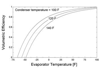
Example 6.2 Determine and plot the effects of condenser and evaporator pressure on the clearance volumetric efficiency, mass flow rate, capacity and power for the ideal system of example 6.1.
The clearance volumetric efficiency is determined over a range of evaporator and condenser temperatures following the calculations of example 6.1, and is plotted in the figure below. As expected, the clearance volumetric efficiency increases as the evaporator temperature increases and as the condenser temperature decreases. For a condensing temperature of 100 F, when the evaporator temperature is also 100 F the condenser and evaporator pressures are equal and the clearance volumetric efficiency is unity. For a condensing temperature of 140 and an evaporator temperature of about –60 F, the clearance volumetric efficiency is zero. This is the condition discussed in relation to Figure 6.2, when the vapor contained in the clearance volume expands to fill the chamber completely at the evaporator pressure.
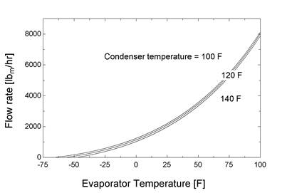
The refrigerant mass flow rate corresponding to the three condensing temperatures is shown on the graph below. Evaporator temperature strongly affects the flow rate, but there is much less of an effect of condenser temperature. At a given evaporator temperature the refrigerant specific volume is the same for all condenser temperatures and the changes in clearance volumetric efficiency shown in the previous figure decreases the flow rate slightly.
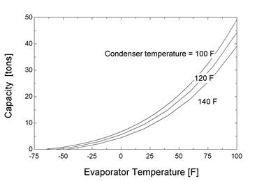
The refrigeration capacity is shown in the next figure. The capacity curves follow those of the mass flow rate in the previous figure. The effects of evaporator and condenser temperature are similar to those of the actual refrigeration system presented in Figure 9.4. The flow rate has the major effect on capacity since the enthalpy change across the evaporator changes only slightly as the condenser or evaporator temperature changes.
The effect of condenser and evaporator temperature on compressor power is shown in the final graph. As evaporator temperature increases from a low value, the power first increases and then decreases. At very low evaporator temperatures there is no power requirement since there is no flow. As the evaporator temperature increases, mass flow rate increases, resulting in an increasing power requirement. Although the mass flow rate is increasing, the pressure difference between evaporator and condenser is decreasing and the work per unit of refrigerant mass becomes less. As a result, the power reaches a maximum and then decreases to zero when the condenser and evaporator temperatures are equal. The power is generally greater for a higher condenser temperature.
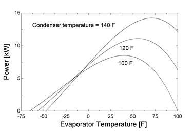
The shape of the power curve affects the electric motor size and current draw. When a refrigeration system is off for a period some refrigerant migrates from the condenser to the evaporator and the pressures throughout the system equalize. Then, when the system is turned on the flow rate through the compressor is very high and the power is low, as shown at the right hand side of the above figures. As the system continues to run the evaporator temperature drops, the flow rate decreases, and the power requirement increases. The power passes through a maximum value and then further decreases as the operating point is reached. The motor and electrical circuit must be designed to handle the maximum power, which is greater than that at the operating condition. Some compressors have mechanisms that limit the flow rate in order to draw less power during start-up.
As discussed in the introduction to this chapter, scroll, screw, and rotary compressors are also commonly used positive displacement devices. In these compressors, the process by which refrigerant vapor is compressed through decreasing the refrigerant volume is similar to that for the reciprocating compressor. The design of these compressors is such that the amount of vapor that re-expands after compression is reduced or eliminated. Leakage of refrigerant past the seals from the high to the low pressure end of the compressor can occur, which allow some of the compressed fluid to flow into the inlet space. Even with leakage, the clearance volumetric efficiency of a scroll, screw, or rotary compressor is usually higher than that of the reciprocating compressor and varies less with condenser and evaporator temperature. As a result, the capacity of refrigeration systems with these compressors is more constant as temperatures vary than systems with reciprocating compressors
The relations presented in this section are useful for gaining insight into the operation of positive displacement devices. Many assumptions are built into their formulation, and irreversibilities due to pressure drop, fluid friction, and heat transfer are neglected. Never the less, the relations are useful in understanding the performance trends of refrigeration systems.
SM 6.2 Performance Correlations for Positive Displacement Compressors
The Air-Conditioning, Heating, and Refrigeration Institute has developed standards for correlating the performance of positive displacement compressors (ANSI/ARI Standard 540, 2004). These correlations are intended to represent the performance of a unit over the range of operation and facilitate the design of refrigeration systems. The form of the correlation is a polynomial in terms of the suction and discharge dewpoint temperatures. The coefficients of the correlation depend on the performance variable but the form of the correlation is the same for all variables and is
![]() (6.16)
(6.16)
where F is any one of the performance variables: power input, refrigerant mass flow rate, motor current, or compressor efficiency, Ts is the suction dewpoint temperature, and Td is the discharge dewpoint temperature. The dewpoint temperatures are the saturation temperatures of the refrigerant at the compressor inlet (evaporating) and outlet (condensing) pressures. The amount of superheat of the refrigerant entering the compressor and subcooling leaving the condenser is held constant in generating the data for the performance maps.
As an example of the correlation, representative overall isentropic efficiency data for a scroll compressor as a function of the suction and discharge dewpoint temperatures are given in Table 6.1. The overall efficiency is the ratio of the isentropic power for the specified inlet conditions and outlet pressure to the actual power input. It includes the effects of motor efficiency and mechanical losses.
Table 6.1 Isentropic efficiency as a function of suction and discharge dewpoint temperatures
Discharge dewpoint Td (F) |
Suction dewpoint temperature Ts (F) |
||||||||
-10 |
0 |
10 |
20 |
30 |
40 |
45 |
50 |
55 |
|
150 |
|
|
|
|
|
0.585 |
0.610 |
0.632 |
0.651 |
140 |
|
|
|
|
0.570 |
0.625 |
0.648 |
0.666 |
0.681 |
130 |
|
|
|
0.552 |
0.613 |
0.662 |
0.680 |
0.695 |
0.704 |
120 |
|
|
0.531 |
0.597 |
0.652 |
0.692 |
0.705 |
0.714 |
0.716 |
110 |
|
0.507 |
0.577 |
0.636 |
0.682 |
0.711 |
0.718 |
0.718 |
0.712 |
100 |
0.481 |
0.554 |
0.616 |
0.666 |
0.700 |
0.714 |
0.711 |
0.701 |
0.683 |
90 |
0.527 |
0.591 |
0.643 |
0.680 |
0.698 |
0.692 |
0.677 |
0.654 |
0.620 |
80 |
0.563 |
0.614 |
0.653 |
0.674 |
0.672 |
0.640 |
0.610 |
0.569 |
0.515 |
Rating Conditions: 20 F superheat, 15 F subcooling, 95 F ambient
(courtesy of Copeland Compressors, Emerson Climate Technologies, Inc.)
Although the information in Table 6.1 represents the performance of the compressor, it is difficult to see the trend for efficiency at conditions that are not at the given temperatures. It would be particularly difficult to determine the operating points for maximum efficiency, for example. Determining the coefficients of the ANSI/ARI correlation (equation 6.16 without the cubic terms), the correlation for the efficiency is
 (6.17)
Equation 6.17 can be used to plot the efficiency as a function of the suction and discharge temperatures, as shown in Figure 6.4. For example, the maximum efficiency at a suction temperature of 25 F would occur with a discharge temperature of 100 F, while at a suction temperature of 40 F the optimal discharge temperature would be 110 to 115 F.
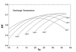
Figure 6.4 Compressor efficiency as a function of suction and discharge temperatures
The correlation of equation 6.16 facilitates the design of a refrigeration system for a given application in which different options are explored. Similarly, the correlations are useful in system simulations of the performance of a refrigeration system.
SM 6.3 Performance Trends for Centrifugal Compressors
Centrifugal compressors are dynamic devices that operate on a different principle than positive displacement compressors, and as a result their performance characteristics are different. Whereas positive displacement compressors increase the refrigerant pressure by reducing its volume, a centrifugal compressor accelerates the refrigerant flow to a high velocity and then decelerates it to produce the pressure rise.
The two major components of a single stage centrifugal compressor are the impeller and the diffuser. The impeller is a circular plate that rotates at high speed and that has vanes that extend in the radial direction. Refrigerant enters the compressor at the center of the impeller, flows radially outward, and leaves the impeller at the outer tips of the blades. The impeller increases the kinetic energy of the refrigerant flow. The high velocity refrigerant then enters the diffuser where it slows down, converting the kinetic energy into flow work that results in a pressure rise. The low speed flow then leaves the compressor and enters the condenser.
The pressure rise through the compressor is essentially determined by the rotational speed, which needs to be high enough to accommodate the maximum pressure difference between the evaporator and condenser. The refrigeration capacity is proportional to the flow rate, and for a given compressor there are limits on the flow rate range. The maximum value occurs when the fluid stalls in the diffuser or the impeller passages. Stalling occurs when the flow velocities are so high that the fluid cannot follow the shapes of the passages and separates from the surface. The lower limit on flow rate is when surge occurs, a condition in which the flow is insufficient for the fluid to fill all of the passages. The flow becomes unsteady and reverses in some of the passages.
For systems with large pressure differences between the evaporator and condenser, two stages of compression, employing two impellers and diffusers connected in series, may be required. Intercoolers between the stages are used to cool the compressed superheated vapor leaving the first stage of compression and reduce the power requirement.
The capacity is modulated by varying the flow rate, and two control methods are used. A centrifugal compressor has pre-rotation vanes in the inlet to impart swirl to the refrigerant and provide a better match between the entering refrigerant velocity and that of the rotating impeller. With vane control, the vanes are closed to reduce the flow when the load is less. Under variable speed control, the rotating speed is changed to produce the desired flow rate. Variable speed control usually requires a variable frequency drive and is more complex, but it results in lower power.
Insight into the operating characteristics of centrifugal compressors can be obtained by analyzing the flow through the impeller and diffuser. Impellers are usually built with vanes that are curved "backwards." For blades of this shape, the increase of pressure due to centrifugal forces is balanced by the decrease of pressure due to the increase of relative velocity. As a result, the pressure along the blade is nearly constant and the potential for secondary flows in the impeller passages is reduced. However, the flow pattern for this geometry is complicated, and a compressor with straight radial vanes and no pre-rotation will be considered in this section to provide some insight into the performance.
A velocity vector diagram for the refrigerant at the edge of the impeller is shown in Figure 6.5. The flow enters the impeller in the axial direction parallel to the impeller shaft and then flows radially outward. At the tip of the blades the fluid has a radial velocity relative to the blades of Vr. The impeller rotates with an angular velocity w, and the absolute tangential velocity of the flow is Vtan. The tangential velocity is generally much higher than the radial velocity.
Figure 6.5 Velocity vectors for a centrifugal compressor
The absolute velocity of the refrigerant leaving the tip of the impeller, Vtip, is the vector sum of the radial and tangential velocities:
![]() (6.18)
(6.18)
Equation 6.18 implies that there is no slip between the refrigerant and the impeller surfaces, which means that the fluid leaves with a tangential velocity equal to that of the blades. In actual machines there is some slippage and the velocity may be less than the tip speed. Assuming that there is no slip corresponds to an ideal compressor and provides relations that give an upper limit on performance.
The conservation of energy principle applied to the flow through the impeller relates the fluid velocities and enthalpies to compressor power. For the impeller wheel as a system, the steady flow conservation of energy principle is
 (6.19)
where the in state is the inlet to the compressor and the tip state is at the tip of the blades, as indicated in Figure 6.5. The power is the shaft power required to rotate the impeller. Even with pre-rotation vanes the kinetic energy of the incoming refrigerant is usually negligible relative to that at the blade tip, allowing the power to be expressed as
 (6.20)
The refrigerant enthalpies at the tip and inlet are also related through the conservation of angular momentum applied to the impeller. For steady flow through the impeller, the conservation of angular momentum is:
![]() (6.21)
(6.21)
where the terms are vectors with both magnitude and direction. The angular momentum flow entering the impeller is given by the vector cross-product of the radius at the inlet and the velocity. In terms of the angular momentum around the axis of rotation, the angular momentum of the incoming stream can be expressed as the scalar relation:
![]() (6.22)
(6.22)
where Vin is the velocity component in the tangential direction at the inlet. For the case of no pre-rotation vanes and no swirl, the refrigerant inlet velocity is along the axis of the impeller and thus the inlet angular momentum is zero. Even with some swirl the angular momentum at the inlet is negligible because both the radius and the tangential velocity are small relative to the values at the blade tip. The angular momentum at the blade tip is given in terms of the impeller radius and tip velocity. The cross-product of the impeller radius and the tip velocity yields the product of the impeller radius and the component of velocity perpendicular to the radius, which is the tip velocity. The angular momentum leaving the impeller is then:
![]() (6.23)
(6.23)
The torque required to turn the impeller is found the expression for angular momentum, equation 6.21, with equation 6.23 for the tip momentum and with negligible inlet momentum. The scalar expression for the torque is:
![]() (6.24)
(6.24)
The power required to turn the impeller can also be expressed as the product of the torque and rotational speed.
![]() (6.25)
(6.25)
where the rotational speed is related to the impeller radius and tangential velocity by:
![]() (6.26)
(6.26)
By combining equations 6.24, 6.25 and 6.26, the power can then be written in terms of the tangential velocity and flow rate as:
![]() (6.27)
(6.27)
There are two relations for the power, equation 6.20 and 6.27. The power can be eliminated to relate the refrigerant enthalpy at the tip of the impeller to the inlet enthalpy and the tip and tangential velocities:
![]() (6.28)
(6.28)
The enthalpy at the tip of the impeller is higher than that at the inlet due to the work done by the impeller. As the refrigerant flows through the diffuser the fluid slows down and the pressure rises. The diffuser process is shown schematically in Figure 6.6.
Figure 6.6 Process in the diffuser of a centrifugal compressor
There is no work done on or by the flow, and an energy balance on the process relates the enthalpy and kinetic energy leaving the impeller to that leaving the diffuser:
 (6.29)
The kinetic energy leaving the diffuser is negligible and so the outlet enthalpy equals the sum of the enthalpy and the kinetic energy entering the diffuser:
![]() (6.30)
(6.30)
Eliminating the tip enthalpy and velocity from equation 6.30 using equation 6.28 allows the outlet enthalpy to be related to that entering the compressor and the tangential velocity at the tip of the impeller:
![]() (6.31)
(6.31)
Equation 6.31 allows the tangential velocity to be related to the enthalpy difference between the inlet and outlet of the compressor:
![]() (6.32)
(6.32)
Equation 6.32 is used to establish the tangential speed needed to produce the desired enthalpy rise across the compressor. The refrigerant enters the compressor from the evaporator, and is near saturation at the evaporator pressure. At the outlet of the compressor, the fluid pressure needs to equal that of the condenser. The minimum tangential speed is obtained when the process is isentropic, in which case the entropy of the outlet state equals that of the inlet state and the outlet enthalpy is at condenser pressure and the entropy of the incoming refrigerant. An isentropic process also yields the minimum power requirement. For a non-ideal process, the compressor efficiency can be introduced to relate the actual enthalpy rise to the ideal. Using the definition of compressor efficiency, the actual outlet enthalpy is:
![]() (6.33)
(6.33)
The mass flow rate through the compressor is related to the refrigerant radial velocity and the flow area at the tip of the impeller. Using the conservation of mass expression, the flow rate through the compressor can be expressed in terms of the properties at the tip of the impeller as
![]() (6.34)
(6.34)
where the density is that of the refrigerant at the tip of the impeller. The flow area Atip is the circumferential area at the tip of the impeller. The height of the space at the tip of the impeller is the blade width, dtip. The mass flow rate can be expressed in terms of the impeller radius and the blade width as:
![]() (6.35)
(6.35)
A centrifugal compressor is positive displacement device in that under design conditions the impeller volume is filled with fluid and discharged at a rate equal to the rotating speed. The mass flow rate can then also be expressed as
![]() (6.36)
(6.36)
where V is the volume of the impeller that is filled with the incoming refrigerant.
The design or analysis of an actual centrifugal compressor is more complicated than as indicated by the equations developed here. However, this analysis is useful to illustrate how impeller size and rotational speed relate to the pressure difference between the condenser and evaporator, and how the system capacity and power are related to the speed and size. The use of these relations to explain some of the design and performance considerations for centrifugal compressors is given in example 6.3.
"Example 6.3 Estimate the design specifications for an ideal centrifugal compressor to be used in a refrigeration system using R-22 that has a design capacity of 1000 tons and a rotating speed of 60 Hz (3600 rpm). The refrigerant leaves the evaporator at a saturation pressure corresponding to 45 F with 5 F superheat, and leaves the condenser saturated at a temperature of 85 F."
"Problem specifications"
Capacity = 1000 "tons" "Cooling capacity"
omega = 60 "Hz" "Rotating speed"
T_e = 45 "F" "Evaporator sat temp"
T_super = 5 "F" "Superheat"
T_c = 85 "F" "Condenser sat temp"
"Determine the mass flow rate required for a cooling capacity of 1000 tons. The state leaving the condenser and entering the expansion valve is saturated at a temperature of 85 F. The enthalpy entering the evaporator is the same as that entering the expansion valve. The enthalpy leaving the evaporator is at a pressure corresponding to a saturation temperature of 45 F with 5 F superheat. "
h_4 = enthalpy(R22, T=T_c, x=0) "Btu/lbm" "Evap inlet enthalpy"
p_e = pressure(R22, T = T_e, x = 1) "psia" "Evap pressure"
T_1 = T_e + T_super "F" "Evap outlet temp"
h_1 = enthalpy(R22, T = T_1, p=p_e) "Btu/lb," "Evap outlet enthalpy"
rho_in = density(R22, T = T_1, p=p_e) "lbm/ft3" "Evap outlet density"
Q_dot_e = Capacity*convert(tons,Btu/hr) "Btu/hr" "Evap heat transfer"
Q_dot_e= m_dot*(h_1 - h_4) "Btu/hr" "Evaporator EB"
"The inlet enthalpy is that leaving the evaporator. The outlet pressure for the compressor corresponds to the condenser saturation temperature of 85 F. For isentropic compression, the outlet enthalpy is at this pressure and the inlet entropy to the compressor. The enthalpy rise across the compressor is the difference between the outlet and inlet enthalpies. The required tangential velocity to produce this enthalpy rise is given by equation 6.30."
p_in = p_e "psia" "Comp inlet pressure"
s_in = entropy(R22, T = T_1, p=p_e) "Btu/lbm-R" "Comp inlet entropy"
h_in = h_1 "Btu/lbm" "Comp inlet enthalpy"
p_out = pressure(R22,T=T_c, x=1) "psia" "Comp outlet pressure"
h_out = enthalpy(R22,s=s_in,p=P_out) "Btu/lbm" "Comp outlet enthalpy"
T_out = temperature(R22,s=s_in,p=P_out) "F" "Comp outlet temp"
V_tan = ((h_out - h_in)*convert(Btu/lbm,ft2/s2))^0.5 "ft/s" "Tangential velocity"
"To lay out the design of an ideal compressor, the impeller radius is related to the tip velocity using equation 6.24. "
V_tan = 2*Pi*r_tip*omega "ft/s" "Tangential velocity"
"To determine the state of the refrigerant as it leaves the impeller, the radial velocity needs to be specified. The radial velocity is determined from the volume of the impeller and the rotating speed using equation 6.36. It is assumed that the blades are straight and of constant height."
Vol = Pi*r_tip^2*delta_tip "ft3" "Impeller volume"
m_dot*convert(1/hr,1/s) = rho_in*Vol*omega "lbm/hr" "Mass flow rate"
"The velocity at the tip is related to the tangential and radial velocity components and the enthalpy at the tip is related to the velocity at the tip and the tangential velocity by equation 6.26"
V_tip^2 = V_tan^2 + V_radial^2 "Velocity relation"
h_tip = h_in + (V_tan^2 - V_tip^2/2)*convert(ft2/s2,Btu/lbm) "Btu/lbm" "Energy balance"
"The compression process is isentropic and the entropy of the refrigerant at the tip equals that entering the compressor. The pressure and the density of the refrigerant at the tip are determined from the tip enthalpy and entropy. "
p_tip = pressure(R22, s=s_in, h=h_tip) "psia" "Pressure at tip"
rho_tip = density(R22,s=s_in, h=h_tip) "lbm/ft3" "Density at tip"
"The flow rate is also given by equation 6.33 in terms of the radial velocity, refrigerant density at the tip, and discharge flow area. The flow area is the product of the impeller circumference, which is related directly to the impeller radius, and the blade width, which is the width of the space through which the refrigerant flows at the tip of the impeller. The blade width that is required to provide the mass flow and outlet velocity is given by equation 6.33."
m_dot*convert(1/hr,1/s) = rho_tip*A_tip*V_radial "lbm/hr" "Continuity equation"
A_tip = 2*Pi*r_tip*delta_tip "ft2" "Tip area"
delta_inch = delta_tip*convert(ft,in) "in" "Blade width"
"The overall energy balance on the compressor gives the power required for the compressor. The power per unit cooling capacity and the COP are also determined."
W_dot = m_dot*(h_out - h_in)*convert(Btu/hr,kW) "kW" "Compressor power"
Kwperton = W_dot/Capacity "kW/ton" "Comp kW/ton"
COP = Q_dot_e/(W_dot*convert(kW,Btu/hr)) "COP"
Results and Discussion
The mass flow rate through the compressor is determined from the desired capacity (1000 tons) and the states entering and leaving the evaporator. The refrigerant leaves the condenser as saturated liquid at a temperature of 85 F, a pressure of 170.4 psia, and an enthalpy of 101.5 Btu/lbm. There is no enthalpy change across the expansion valve and the refrigerant enthalpy entering the evaporator is also 101.5 Btu/lbm. The pressure, enthalpy, and entropy of the refrigerant leaving the evaporator are 90.8 psia, 176.2 Btu/lb, and 0.4175 Btu/lb-F, respectively. The flow rate of refrigerant required to produce the desired capacity is determined from an energy balance on the evaporator to be 161,800 lbm/hr.
The compression process is isentropic from the inlet state to the condenser pressure. For isentropic compression, the refrigerant leaves at an enthalpy of 182.9 Btu/lbm and a temperature of 108 F. The enthalpy increases 6.7 Btu/lbm through the compressor and the tangential velocity needed to produce this enthalpy rise is 410 ft/s. This is a relatively high velocity for a vapor, equal to about one-half the speed of sound. The impeller rotates at 60 Hz and the impeller radius to achieve this tangential velocity is 1.09 ft, or a diameter of 2.18 ft.
From the volume displaced by the compressor and the rotating speed, the radial velocity of the refrigerant at the tip is 24.5 ft/s. The resultant tip velocity is 410 ft/s and the enthalpy of the refrigerant at the tip is 179.5 Btu/lbm.
For these ideal calculations the compression process is isentropic from the inlet to the tip of the impeller. Using the entropy of the refrigerant at the inlet and the enthalpy of the refrigerant at the tip yields a pressure of the refrigerant at the tip of 124.9 psia and a density of 2.17 lbm/ft3. The pressure at the tip is intermediate between that at the inlet and the outlet. The density together with the radial velocity and mass flow rate allows the blade width, which is the width of the space through which the refrigerant flows at the tip of the impeller, to be determined as 0.124 ft or 1.49 inches. The design leads to a relatively large diameter impeller with a relatively small blade width. If a smaller capacity compressor were desired a much smaller spacing at the blade tip would be needed. The design constraints of centrifugal compressors tend to make them economic for large capacity systems.
Designing for operation at a higher rotational speed would result in a smaller diameter rotor. If the compressor rotational speed were twice the electrical frequency, or 7200 rpm, the required diameter could be halved to 1.08 ft and the blade height would increase 3.0 in. This might be a more suitable geometry in terms of the manufacturing. These calculations demonstrate that centrifugal machines need to be physically large and rotate rapidly to produce the desired pressure rises, and that the resulting capacity is large.
For a given centrifugal compressor, the performance follows the trends given by the simple analysis presented here. A compressor map represents the effect that the speed, flow rate, and pressure rise have on efficiency. It is usual to represent the pressure rise as the pressure ratio across the compressor, which is the ratio of the condenser pressure to that in the evaporator, and to plot the performance as the pressure ratio as a function of flow rate. A representative compressor map is given in Figure 6.7.
Figure 6.7 Centrifugal compressor performance map
For a given compressor, the maximum efficiency occurs at one flow rate and pressure ratio, which is the center of the concentric ovals in Figure 6.7. At this optimal condition, the rotational speed and flow rates are such that there is a good match between the velocity vectors and the surfaces of the impeller and the diffuser. At conditions removed from this point of maximum efficiency, the fluid strikes the blade and diffuser surfaces at an angle, creating pressure losses.
The surge line represents a lower limit for the flow rate through the compressor, and is shown on the left of the map in Figure 6.7. In a centrifugal compressor, surge occurs when the refrigerant flow is too low to completely fill the passages in the impeller. The flow stalls, which means that the flow reverses temporarily between some of the blades until enough refrigerant accumulates to fill the passage and discharge into the diffuser. Surge produces fluctuations in the flow that cause the compressor power and speed to fluctuate. The resulting vibrations can be detrimental to compressor performance and it is not advisable to operate a centrifugal compressor in the surge condition.
A higher limit for the flow rate occurs when the flow reaches sonic velocities in the passageways. When the flow velocity at the minimum area equals the speed of sound, the mass flow rate does not increase as the pressure difference increases, in contrast to the flow through subsonic passages. The flow is then choked and cannot increase. This limit is shown on the right side of Figure 6.7.
A number of nondimensional parameters have been developed to represent the performance of centrifugal compressors. Correlations of these nondimensional quantities are useful in design, for scaling a compressor designed for one application to another situation, and in evaluating performance. These parameters will be discussed briefly here, and they are described in more detail in the literature (ASHRAE 1993, Logan, 1993).
The flow coefficient is a non-dimensional representation of the flow rate through the compressor, and is defined as
![]() (6.37)
(6.37)
where the refrigerant volume flow rate ![]() is evaluated at the compressor inlet. The term
is evaluated at the compressor inlet. The term ![]() is the rotational speed and Do is the impeller diameter. For satisfactory compressor performance, the flow parameter should be in the range of 0.11 to 0.21, with optimal performance obtained with values between 0.15 and 0.18 (ASHRAE, 1993). Values in the optimal range provide a good match between the velocity at the tip and that entering the diffuser.
is the rotational speed and Do is the impeller diameter. For satisfactory compressor performance, the flow parameter should be in the range of 0.11 to 0.21, with optimal performance obtained with values between 0.15 and 0.18 (ASHRAE, 1993). Values in the optimal range provide a good match between the velocity at the tip and that entering the diffuser.
The non-dimensional work coefficient, which is sometimes called the head coefficient, is defined as
![]() (6.38)
(6.38)
where w is the work per unit mass or specific work, and is the compressor power divided by the mass flow rate. For well-designed compressors, values of the work coefficient are in the range of 4 to 7. Another coefficient often employed is the specific speed of the compressor, which is a combination of the flow and work coefficients. The specific speed, which eliminates the diameter of the impeller from the parameter, is defined as
![]() (6.39)
(6.39)
The tip Mach number is also an important parameter, and is defined as the ratio of the tip speed to the speed of sound in the refrigerant. As discussed earlier, when sonic conditions are reached in the flow inside the compressor the Mach number is unity and the flow is choked.
![]() (6.40)
(6.40)
It is desirable to keep the Mach number below unity.
The performance of a centrifugal compressor may also be represented using these non-dimensional parameters. Figure 6.8 is a schematic depiction of compressor performance on non-dimensional coordinates, where the flow coefficient is plotted as a function of the work coefficient.
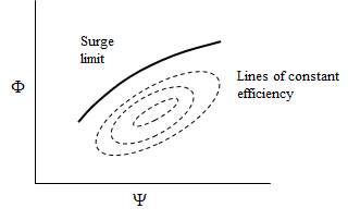
Figure 6.8 Representation of centrifugal compressor performance
As in Figure 6.7, the contour lines are lines of constant compressor efficiency, with the maximum efficiency in the oval region in the middle of the plot. Example 6.4 illustrates how the non-dimensional parameters are calculated for a given compressor.
Example 6.4 Determine the non-dimensional flow, power, speed, and Mach number for the compressor design of example 6.3.
The EES code of Example 6.3 is used to calculate the necessary dimensional parameters. The following code is used to determine the non-dimensional parameters.
"Determine the inlet specific volume and the volume flow rate at the inlet conditions"
v_in = volume(R22, T = T_1, x = 1) “ft3/lbm” “Inlet specific volume”
V_dot = m_dot*v_in*convert(1/hr,1/s) “ft3/s” “Volumetric flow rate”
"Determine the non-dimensional flow coefficient using equation 6.37 with the volume flow rate, rotating speed, and tip radius."
Phi = V_dot/(omega*(2*r_tip)^3) “Flow coefficient”
"Determine the work coefficient using equation 6.38 and the rotating speed and tip radius. The work per unit mass is the difference between the inlet and outlet refrigerant enthalpies. "
Psi = (h_out - h_in)*convert(Btu/lbm,ft2/s2)/(omega*2*r_tip)^2 “Work coefficient”
"Determine the specific speed using the flow coefficient and work coefficient in equation 6.39"
N_s = Phi^0.5/Psi^0.75 “Specific speed”
"Determine the Mach number at the tip, which is the ratio of the tip speed to the acoustical velocity. The acoustical velocity (speed of sound) is as function of temperature and pressure. "
T_tip = temperature(R22, s=s_in, h=h_tip) “F” “Temp at impeller tip”
V_sonic = SOUNDSPEED(R22,T=T_tip,P=P_tip) “ft/s” “Speed of sound”
Mach = V_tip/V_sonic “Mach number”
"Determine the pressure ratio across the compressor using the inlet and outlet pressures"
P_ratio = P_out/P_in “Pressure ratio”
Results and Discussion
Using the specific volume at the compressor inlet conditions, the volume flow rate at the compressor inlet is 42 ft3/s. The non-dimensional flow coefficient determined for the compressor operating at 60 Hz is 0.022. This value is below the recommended range of 0.11 to 0.21, and there would be a mismatch between the fluid velocities and the impeller speed. Correspondingly, the efficiency would be well below the optimal range, as indicated by Figure 6.8. If the second design of example 6.3 were chosen, in which the compressor rotates at twice the line frequency, the diameter would be 1.58 ft. The flow coefficient would be 0.09, which is closer to the desired range.
The work coefficient is given by equation 6.37, where the work per unit mass is the enthalpy difference across the compressor. The coefficient is 9.87, which is close to the desired range. The work coefficient would have the same value if the compressor rotated at 120 Hertz because the tip speed, which is proportional to the product of rotational speed and diameter, is the same for both designs.
The specific speed is 0.027. The speed of sound for refrigerant R-22 at the tip pressure and temperature is 553 ft/s, which is about one-half that for air. The tip Mach number, which is the ratio of the tip speed to the acoustical velocity, is 1.08. The value is greater than unity, which means that the flow is supersonic leaving the tip. The Mach number would be the same for both designs since the tip velocity is the same for both.
Example 6.4 illustrates the application of the scaling laws for centrifugal machines using the compressor design of Example 6.3. For the ideal compressor designs of Example 6.3, some of the non-dimensional parameters are outside the recommended ranges. The design of an actual compressor would bring in these scaling laws as well detailed design ideas developed through practice.
SM 6.4 Expansion Devices
The expansion device in a refrigeration system is the component that reduces the pressure of the refrigerant from that of the condenser to that of the evaporator. Additionally, the expansion device regulates the refrigerant flow rate to ensure that there is two-phase flow on most of the evaporator surface. Several different types of expansion devices are employed depending on the capacity of the system and the type of load. The basic types of expansion devices are capillary tubes, thermostatic expansion valves, constant pressure expansion valves, float valves, and electronic expansion valves.
Capillary tubes are the simplest type of expansion device and are used for small capacity systems. A capillary tube has a very small diameter and is installed in the tubes that run between the condenser outlet and evaporator inlet. The device does not involve capillary action but is a throttling device that reduces the pressure of the flow. In a refrigeration system design, the length and diameter of the capillary tube are selected to provide the needed pressure drop and flow rate for the desired capacity at specified condenser and evaporator operating pressures.
The flow through the capillary tube is complex in that the refrigerant enters as a subcooled liquid and leaves as a two-phase mixture. At some point in the tube the pressure falls below the saturation value and vapor begins to be produced. The volume of vapor continues to increase as the two-phase mixture flows through the tube. The flow pattern is similar to that for boiling in a tube as described in Chapter SM 7.
The fixed design of the capillary tube means that the refrigeration system does not respond well to changes in the pressure levels of the condenser and evaporator. If the temperature of the cooled fluid in the evaporator is lower, for example, the evaporator pressure drops, the pressure difference across the capillary tube increases, and the flow through the capillary tube increases. In contrast, if the evaporator pressure is decreased, the compressor will be able to pump less flow. The performance characteristics of the compressor and capillary tube are shown schematically in Figure 6.9.
Figure 6.9 Flow characteristics of compressor and capillary tube
Capillary tubes are thus most appropriate when the source and sink temperatures do not vary over a large range. Capillary tubes are ideal for home refrigerators and dehumidifiers for which the hot and cold temperatures are basically constant. They are used for window air conditioners for which the evaporator temperature is essentially constant. The variations of condenser pressure due to changes in the ambient temperature affect the flow somewhat, but the systems operate satisfactorily.
Thermostatic expansion valves control the amount of superheat of the refrigerant flow entering the compressor. As shown in Figure 6.10, the expansion valve modulates the flow from the condenser to the evaporator. A bulb filled with refrigerant in the two-phase state is attached to the suction line of the compressor. The refrigerant in the bulb is at the same temperature as the refrigerant flowing to the compressor, and the pressure in the bulb is then the saturation pressure of the temperature of the refrigerant flow. The refrigerant flow to the compressor is superheated, and so the pressure in the bulb is greater than the pressure in the evaporator. The pressure on the top of the diaphragm is thus greater than that in the evaporator.
The pressure in the valve on the underside of the diaphragm is the saturation pressure in the evaporator. The force of the spring is upwards on the diaphragm and acts in the same direction as the evaporator pressure. The spring tension is adjustable and can be set to produce a force proportional to a pressure difference corresponding to the desired amount of superheat. Typically, the amount of superheat is 5 to 10 F (3 to 5 C).
Figure 6.10 Thermostatic expansion valve
(Courtesy of Danfoss A/S, Denmark)
Thermostatic control valves are widely used in the refrigeration and air-conditioning fields. The flow of refrigerant can be controlled over a range to accommodate varying operating conditions. However, the nonlinear relation between the saturation pressure and temperature means that at lower suction temperatures a much larger pressure difference between the bulb and refrigerant is needed to produce a given amount of superheat than at a higher suction temperature. The spring tension is set for a given superheat at design conditions, which corresponds to a given, fixed pressure difference. If the refrigerant temperature in the evaporator is lowered, a greater amount of superheat is needed to balance the pressures. This can result in "starving" the evaporator by increasing the amount of surface area needed to superheat the gas and reducing the surface area where the phase change occurs. Correspondingly, at higher refrigerant temperatures, the amount of superheat needed to produce the pressure difference is reduced and the refrigerant exits the evaporator closer to the liquid state.
Electronic expansion valves are an improvement over thermostatic valves in that the amount of superheat can be maintained over a wider range operating conditions. The electronic valve uses a thermistor to sense the temperature of the refrigerant to the compressor. Together with a control module and other sensors, the amount of superheat can be set precisely and maintained over the operating range. The electronic expansion valve is more expensive than the thermostatic valve but provides better control. It can be integrated into an energy management system, which can set the level of superheat and optimize the system performance.
Float expansion valves are used in large refrigeration systems to maintain a fixed liquid level in the evaporator. A expansion value consists of a ball float in a chamber that activates a valve, similar to the flash intercooler described in Chapter 15. A low-side float expansion valve is used to control the liquid level in a flooded evaporator. When the refrigerant level in the evaporator drops the float lowers, opening a valve and allowing more refrigerant to enter.
Lastly, a constant pressure expansion valve is sometimes used. that maintains a constant pressure in the evaporator. Because the valve cannot respond to changes in evaporator temperature it is applicable only to systems in which the evaporator temp is constant.
In summary, there are several types of expansion devices in use in refrigeration systems. They serve the two purposes of reducing the refrigerant pressure and maintaining refrigerant flow through the evaporator. Small systems of less than 10 tons capacity use capillary tubes. Thermostatic expansion valves are widely used and suitable for most applications. For situations in which the load or evaporator temperature varies over a large range or precise control is needed, electronic expansion valves are employed.
SM 6.5 System-Component Integration
The performance characteristics of the components that make up a basic refrigeration system have been presented for compressors and expansion valves in this supplementary chapter and for heat exchangers in Chapter 13 Heat Exchangers for Heating and Cooling Applications. The design process for a refrigeration, air conditioning, or heat pump system is to select the parameters of each component and achieve the desired performance at the design conditions. Some of the tradeoffs in selecting design parameters and the effect of operating conditions on a designed system will be illustrated in this section.
The basic refrigeration system and a pressure-enthalpy diagram are shown in Figure 6.11. A criteria used in designing a system would be to provide a given cooling capacity (![]() ) at specified design conditions, which would be the temperature of the cooled fluid or space (TL) and the temperature for heat rejection (TH). The evaporator, condenser, compressor, and expansion valve would then be selected to meet these criteria.
) at specified design conditions, which would be the temperature of the cooled fluid or space (TL) and the temperature for heat rejection (TH). The evaporator, condenser, compressor, and expansion valve would then be selected to meet these criteria.
Figure 6.11 Schematic and process diagram for a refrigeration system
The cooling capacity, which is the heat transfer rate in the evaporator ![]() , is given in terms of the refrigerant flow rate and enthalpies.
, is given in terms of the refrigerant flow rate and enthalpies.
![]() (6.41)
(6.41)
where ![]() is the refrigerant flow rate and the enthalpies are defined on Figure 6.11. The heat transfer rate is also given by a heat exchanger expression and would relate the low temperature fluid TL to the temperature of the evaporating fluid Te. The heat transfer rate for an evaporator can be approximated as the product of an overall heat transfer coefficient UA and the temperature difference between the low temperature fluid and the evaporating fluid (Section 13.3):
is the refrigerant flow rate and the enthalpies are defined on Figure 6.11. The heat transfer rate is also given by a heat exchanger expression and would relate the low temperature fluid TL to the temperature of the evaporating fluid Te. The heat transfer rate for an evaporator can be approximated as the product of an overall heat transfer coefficient UA and the temperature difference between the low temperature fluid and the evaporating fluid (Section 13.3):
![]() (6.42)
(6.42)
This is an approximation in that the low temperature fluid is not constant in the evaporator and the log-mean-temperature-difference should be employed. Further, heat transfer associated with condensation is not accounted for in this expression. However, this relation is sufficiently accurate for illustrating the performance of an evaporator.
Equation 6.42 shows that as the design temperature difference between the low temperature fluid and the evaporating refrigerant is reduced the overall heat transfer coefficient must be larger in order to transfer the desired amount of heat. For a given heat exchanger surface with a conductance U, there is then a tradeoff between the heat transfer area A, representing the physical size and cost of the evaporator, and the temperature difference, which affects the compressor power requirement.
The physical size of the compressor and electric motor are related to both the refrigerant flow rate and the temperature of the evaporating fluid. For a positive displacement compressor, the compressor work is given in terms of the volumetric efficiency, rotating speed, and refrigerant pressures at suction and suction and discharge conditions as (Section SM 6.1)
 (6.43)
The electrical power that must be supplied is the determined from the compressor work and combined motor-compressor efficiency as
![]() (6.44)
(6.44)
There is a strong effect of the evaporator temperature and pressure on the power requirement. For lower evaporating temperatures, corresponding to smaller evaporator area and larger temperature difference, the motor power requirement is higher. The evaporator heat transfer area and the size of the electrical motor as functions of the evaporating temperature are shown schematically in Figure 6.12.
Figure 6.12 Displacement volume and evaporator area as functions of temperature
Figure 6.12 shows the tradeoffs between the electric motor size (and cost) and evaporator area (and cost). The heat transfer area increases exponentially as the evaporating fluid temperature approaches that of the cold fluid, and the evaporator is correspondingly larger and more costly. However, the compressor size and cost is lower, although it approaches limit. Correspondingly, for lower condensing temperatures, the electric motor must be larger and thus more costly, although the evaporator is less costly. The evaporating temperature in a given system is based on economic considerations, which determine the evaporator and compressor-electric motor physical sizes.
Similar considerations hold for the selection of the condensing temperature. The displacement volume and compressor-electric motor size are less sensitive to the condensing temperature than the evaporating temperature, but more power is required for higher condensing temperatures. As with the evaporator, the required condenser area is less for larger temperature differences between the condensing fluid and high temperature. The selection of the condensing temperature or the size of the condenser are also economic decisions.
The selection of an expansion valve is based on flow rate and the final selection of condensing and evaporating temperatures and the corresponding pressures. The type of expansion valve is based on the expected load characteristics and the cost of different valves. An expansion valve needs to be selected that will provide the desired pressure drop and meet the flow criteria.
Although a refrigeration system is designed for given conditions, it does not operate only at the design point. For example, if the source for heat rejection is ambient air, the temperature would have daily and seasonal fluctuations. Similarly, if the setpoint for the cold space were changed the temperatures throughout the system would change. The refrigeration system would continue to operate, but would have different balance points, which are the different operating temperatures and pressures for that conditions.
Example 6.5 illustrates the change in the operating (balance) points for changes in operating conditions. The compressor model of Example SM 6.1 and 6.2 is used to create a map of compressor performance. The heat transfer in the condenser and evaporator are modeled using equation 6.42.
Summary
Vapor compression refrigeration systems are designed for a wide range of cooling and/or heating capacities. Small units with capacities on the order of a ton are designed for use in home refrigerators and room air conditioners, while systems with thousands of tons of capacity are designed for commercial and industrial facilities. Different compressor types are appropriate for the different capacity ranges. Reciprocating, rotary and scroll compressors are positive displacement units and found in smaller systems. Screw compressors are positive displacement units suitable for the larger refrigerant flows found in the intermediate capacity range, whereas centrifugal machines are most suitable for large capacity applications.
In positive displacement compressors, the compression process is often modeled using a polytropic process that accounts for heat transfer during the process. The pressure differences between the intake and discharge directly affect the refrigerant mass that can be pumped through the compressor. Pressure drops through the valves and openings in a compressor increase the work and reduce the mass flow. The volumetric efficiency is a measure of the amount of mass that a compressor can process. As the pressure difference between the condenser and evaporator increases, the mass flow rate and volumetric efficiency decrease.
The power required for a positive displacement compressor is the product of the volumetric efficiency, the work per unit mass, and the flow rate. The work increases as the pressure difference between the condenser and evaporator increases, reaches a maximum, and then decreases. The capacity is proportional to the mass flow rate and decreases continuously as the pressure difference increases. The coefficient of performance (COP) also decreases strongly as evaporator temperature decreases.
Centrifugal compressors employ a different process for the compression process than positive displacement machines. In these machines the refrigerant is first accelerated to a high velocity and then decelerated to produce the pressure rise. Centrifugal compressors are inherently physically large and need to rotate at high speeds to produce high fluid velocities. As a result the refrigerant flow rates and refrigeration capacities of systems with centrifugal compressors are large.
The performance characteristics for compressors can be coupled to those for the heat exchanger and expansion components to determine the overall performance of a refrigeration system. The combination allows the change in operating state and performance to be determined when the variables such as the external temperatures for the cooling and heat rejection fluids change.
SM 6.7 Nomenclature
C clearance volume fraction
D diameter
F performance variable
h specific enthalpy
![]() mass flow rate
mass flow rate
M Mach number
![]() momentum rate
momentum rate
n polytropic exponent
Ns specific speed
![]() rotational speed
rotational speed
p pressure
![]() evaporator heat flow rate
evaporator heat flow rate
r radius
T temperature, torque
V volume, velocity
Vs speed of sound
![]() volume flow rate
volume flow rate
v specific volume
w work per unit mass
![]() compressor power
compressor power
![]() electric power
electric power
d thickness
F nondimensional flow coefficient
hc compressor efficiency
hV volumetric efficiency
hV,C volumetric efficiency based on clearance volume
Y nondimensional work coefficient
r density
w rotational speed
Subscripts
a,b,c,d state points
c condenser
cl clearance
cyl cylinder
d discharge
disp displacement volume
in inlet
e evaporator
low low
L low temperature
o outer
out outlet
r radial
s suction, isentropic
tan tangential
tip tip conditions
SM 6.8 References
ANSI/ARI Standard 540-2004, "Performance Rating of Positive Displacement Refrigerant Compressors and Compressor Units," AHRI, Arlington, VA, 2004
"ASHRAE Handbook HVAC Systems and Equipment," Chapter 33, ASHRAE, Atlanta, GA, 1996.
Brumbaugh, J. E. "HVAC Fundamentals," J Wiley and Sons, 2004
Cohen, R, E. Groll, W. H. Harden, K. E. Hickman, D. K. Mistry, and E. Muir, "Compressors," Chapter 4.7,
Jaehnig, D. “A Semi-empirical Method for Modeling Reciprocating Compressors in Residential Refrigerators and Freezers,” MS Thesis, Solar Energy Laboratory, University of Wisconsin, May, 1999.
Logan, E. "Turbomachinery," Marcel Dekker, New York, 1993.
SweetHaven Publishing Services, http://www.free-ed.net/sweethaven/MechTech/Refrigeration/.
SM 6.9 Problems
Problems in English Units
6.1 Determine the COP, capacity, and discharge temperature for a refrigeration system with a reciprocating compressor. The compressor has a displacement volume of 0.05 ft3, a clearance volume fraction of 0.05, and rotates at 1740 rpm. The refrigerant is R-22. The operating conditions are:
a) Evaporating temperature of 25 F and condensing temperature of 120 F.
b) Evaporating temperature of 10 F and condensing temperature of 120 F.
c) Evaporating temperature of 25 F and condensing temperature of 130 F.
d) Draw some conclusions from your results.
6.2 Determine the COP, capacity, and discharge temperature for a refrigeration system with a reciprocating compressor. The compressor has a displacement volume of 0.05 ft3, a clearance volume fraction of 0.05, and rotates at 1740 rpm. The refrigerant is R-22 and it leaves the evaporator as saturated vapor at 25 F and the condenser as saturated liquid at 120 F. Evaluate the performance for two situations:
a) A clearance volume fraction of 0.05.
b) A clearance volume fraction of 0.075.
c) Draw some conclusions from your results.
6.3 Determine the power requirement, cooling capacity, coefficient of performance and discharge temperature for a refrigeration system with a reciprocating compressor. The compressor has a displacement volume of 0.05 ft3, a clearance volume fraction of 0.05, and rotates at 1740 rpm. The refrigerant leaves the evaporator as saturated vapor at 25 F and the condenser as saturated liquid at 120 F. Evaluate the performance for the following refrigerants:
a) R-22, a traditional refrigerant that is scheduled for replacement
b) R-407C, a refrigerant that will replace R22 with lower environmental impact than R22
c) R-717, ammonia, an alternative refrigerant that is used in the many industries but that as a potential safety hazard
d) Draw some conclusions from your results.
6.4 An air-conditioning system is designed to use R-22 as the refrigerant. At design conditions the reciprocating compressor operates at 1750 rpm, has a total displacement volume of 0.9 ft3 and a clearance volume of 0.035 ft3. The condenser is air cooled and at design conditions the inlet air temperature is 95 F and the temperature difference between the entering air and the refrigerant is 15 F. The evaporator is a direct expansion coil and at design conditions the supply air temperature is 50 F and the temperature difference between the supply air and refrigerant is 15 F. The average ambient temperature is 80 F and the system operates 3000 hours at full-load conditions. Electricity costs are $0.10/kWh for energy and $ 120/kW for demand.
a. Determine the COP, capacity, compressor power, and refrigerant flow rate for design conditions.
b. Determine the total cooling (ton-hrs) and the cost of operation ($).
c. Determine how much more the building owner could pay for an improved design with larger heat exchangers that reduce the temperature differences to 10F. The total cooling is the same as in part b).
6.5 The performance characteristics (capacity and power) for a refrigeration system with a reciprocating compressor are given in the figure below. The four cylinder semi-hermetic reciprocating compressor has a bore of 2.38 in., a stroke of 1.75 in., and operates at a speed of 1740 rpm.
a. Develop a mechanistic model for the reciprocating compressor and adjust the clearance volume and motor-compressor efficiency to get “good” agreement with the data. An isentropic exponent of 1.15 will be close for the refrigerant. Compare the capacity and the power over the range of evaporator and condenser temperatures from the model with the data.
b. Draw some conclusions from your results.

6.6 The reciprocating compressor model of example 6.1 is to be used in the design of a cooling system for a warehouse. The design load is a sensible load of 750 tons and provided by a constant flow of air through a single DX coil with a temperature difference between the air and refrigerant in the coil of 10 F. The warehouse is maintained at a 25 F dry bulb. The condenser is air-cooled and the outdoor design dry bulb is 95 F. The condenser is designed with a 10 F temperature difference between refrigerant and ambient.
a. Determine the evaporator temperature, compressor size (total displacement), electric motor size (kW) and COP that will meet the design specifications
b. Estimate the annual operating cost assuming that refrigeration is required all of the year at the annual average temperature of the location, which is 60 F. The system is turns on and off to meet the load. Electrical costs are $0.10/kWh.
6.7 The average cooling requirement for a small building is 15 tons but the cooling capacity of the air conditioner is 30 tons. The three alternative methods to be evaluated for modulating the capacity are: i) varying the compressor speed, ii) throttling the suction gas, and iii) bypassing some discharge gas to the evaporator inlet. The evaporating temperature is 35 F and the condensing temperature of 100 F. Saturated liquid leaves the condenser and saturated vapor leaves the evaporator. The volumetric efficiency of the compressor can be described by the following equation.

where the polytropic exponent is equal to 1.18. The overall compressor displacement volume is 38.9 cubic inches per cycle and the rated compressor speed is 3600 rpm.
For variable-speed control, assume that the compressor speed (rpm) is adjusted to give the refrigerant flow rate necessary to meet the load. For the suction gas throttling control, the refrigerant flow rate is reduced using a valve that lowers the inlet pressure and changes suction gas density and the volumetric efficiency. For the bypass control, the refrigerant flow rate through the compressor is constant. However, some of the compressed vapor bypasses the condenser, is throttled to the evaporator pressure, and then introduced directly into the evaporator.
c. Rank the control methods in terms of system performance and explain your reasons for your order.
6.8 Estimate the design specifications for an ideal centrifugal compressor to be used in a refrigeration system using R-22 that has a design capacity of 1000 tons. The refrigerant leaves the evaporator at a saturation pressure corresponding to 20 F with 5 F superheat, and leaves the condenser saturated at a temperature of 100 F. Vary the rotating speed from 15 Hz to 60 Hz (3600 rpm). Discuss the effect of rotating speed on the design specifications.
6.9 A centrifugal compressor has an impeller diameter of 1.5 ft, a blade height of 0.7 in, and operates at 10,000 rpm. The refrigerant is R22, the design condenser temperature is 120 F, the evaporator temperature is 40 F, and the refrigerant enters the compressor as saturated vapor. Using the model for a centrifugal compressor with straight vanes on the impeller:
Problems ins SI units
6.10 Determine the COP, capacity, and discharge temperature for a refrigeration system with a reciprocating compressor. The compressor has a displacement volume of 0.002 m3, a clearance volume fraction of 0.05, and rotates at 60 hertz. The refrigerant is R-22. The operating conditions are:
a) An evaporating temperature of – 5 C and a condensing temperature of 50 C.
b) An evaporating temperature of – 15 C and a condensing temperature of 50 C.
c) An evaporating temperature of – 5 C and a condensing temperature of 60 C.
d) Draw some conclusions from your results.
6.11 Determine the COP, capacity, and discharge temperature for a refrigeration system with a reciprocating compressor. The compressor has a displacement volume of 0.002 m3 and rotates at 60 hertz. The refrigerant is R-22, and it leaves the evaporator as saturated vapor at – 5 C and the condenser as saturated liquid at 50 C. Evaluate the performance for two situations:
a) A clearance volume fraction of 0.05.
b) A clearance volume fraction of 0.075.
c) Draw some conclusions from your results.
6.12 Determine the volumetric efficiency, mass flow rate, power requirement, cooling capacity, coefficient of performance and discharge temperature for a refrigeration system with a reciprocating compressor. The compressor has a displacement volume of 0.002 m3, a clearance volume fraction of 0.05, and rotates at 60 hertz. The refrigerant leaves the evaporator as saturated vapor at – 5 C and the condenser as saturated liquid at 50 C. Evaluate the performance for the following refrigerants:
a) R-22, a traditional refrigerant that is scheduled for replacement
b) R-407C, a refrigerant that will replace R22 with lower environmental impact than R22
c) R-717, ammonia, an alternative refrigerant that is used in the many industries but that as a potential safety hazard
d) Draw some conclusions from your results.
6.13 An air-conditioning system is designed to use R-22 as the refrigerant. At design conditions the reciprocating compressor operates at 29 Hz, has a total displacement volume of 0.025 m3 and a clearance volume of 750 cm3. The condenser is air cooled and at design conditions the inlet air temperature is 35 C and the temperature difference between the entering air and the refrigerant is 8 C. The evaporator is a direct expansion coil and at design conditions the supply air temperature is 12 C and the temperature difference between the supply air and refrigerant is 8 C. The average ambient temperature is 26 C and the system operates 3000 hours at full-load conditions. Electricity costs are $0.010/kWh for energy and $120/kW for demand.
a. Determine the COP, capacity, compressor power, and refrigerant flow rate for design conditions.
b. Determine the total cooling (kWh) and the cost of operation ($).
c. Determine how much more the building owner could pay for an improved design with larger heat exchangers that reduce the temperature differences to 4 C. The total cooling is the same as in part b).
6.14 The performance characteristics (capacity and power) for a refrigeration system with a reciprocating compressor are given below. The operating parameters of this four cylinder semi-hermetic reciprocating compressor are a speed of 29 Hz, a bore of 60 mm, and a stroke of 45 mm. The refrigerant has an isentropic exponent of 1.15.
a) Convert the English units to SI units and develop a mechanistic model for a refrigeration system with a reciprocating compressor. Adjust the clearance volume and motor-compressor efficiency to get “good” agreement with the data. Calculate the capacity and the power over the range of evaporator and condenser temperatures. Superimpose a plot of the results from the model over the data.
b) Draw some conclusions from your results.
6.15 The reciprocating compressor model of example 6.1 is to be used in the design of a cooling system for a warehouse. The design load is a sensible load of 2500 kW and provided by a constant flow of air through a single DX coil with a temperature difference between the air and refrigerant in the coil of 5 C. The warehouse is maintained at a -5 C dry bulb. The condenser is air-cooled and the outdoor design dry bulb is 35 C. The condenser is designed with a 7 C temperature difference between refrigerant and ambient.
a. Determine the evaporator temperature, compressor size (total displacement), electric motor size (kW) and COP that will meet the design specifications
b. Estimate the annual operating cost assuming that refrigeration is required all of the year at the annual average temperature of the location, which is 18 C. The system is turns on and off to meet the load. Electrical costs are $0.10/kWh.
6.16 The average cooling requirement for a small building is 50 kW but the cooling capacity of the air conditioner is 100 kW. The three alternative methods to be evaluated for modulating the capacity are: i) varying the compressor speed, ii) throttling the suction gas, and iii) bypassing some discharge gas to the evaporator inlet. The evaporating temperature is 5 C and the condensing temperature of 40 C. Saturated liquid leaves the condenser and saturated vapor leaves the evaporator. The volumetric efficiency of the compressor can be described by the following equation.

where the polytropic exponent is equal to 1.18. The overall compressor displacement volume is 0.00055 m3 per cycle and the rated compressor speed is 60 Hz.
For variable-speed control, assume that the compressor speed is adjusted to give the refrigerant flow rate necessary to meet the load. For the suction gas throttling control, the refrigerant flow rate is reduced using a valve that lowers the inlet pressure and changes suction gas density and the volumetric efficiency. For the bypass control, the refrigerant flow rate through the compressor is constant. However, some of the compressed vapor bypasses the condenser, is throttled to the evaporator pressure, and then introduced directly into the evaporator.
c. Rank the control methods in terms of system performance and explain your reasons for your order.
6.17 Estimate the design specifications for an ideal centrifugal compressor to be used in a refrigeration system using R-22 that has a design capacity of 3500 kW. The refrigerant leaves the evaporator at a saturation pressure corresponding to – 10 C with 3 C superheat, and leaves the condenser saturated at a temperature of 40 C. Vary the rotating speed from 15 Hz to 60 Hz. Discuss the effect of rotating speed on the design specifications.
6.18 A centrifugal compressor has an impeller diameter of 0.5 m, a blade height of 1.75 cm, and operates at 160 Hz. The refrigerant is R22, the design condenser temperature is 50 C, the evaporator temperature is 5 C, and the refrigerant enters the compressor as saturated vapor. Using the model for a centrifugal compressor with straight vanes on the impeller:
a. Determine the capacity, kW/ton, and the compressor outlet pressure at design conditions.
b. For the over the same speed, determine the capacity, COP, and the compressor outlet pressure for evaporator temperatures of - 5 to 15 CF
c. For evaporator temperatures higher than the design temperature, the capacity and compressor outlet pressure is higher than that for the design conditions and represents a loss. Variable speed control could be used to reduce the outlet pressure. Determine the rotating speed that would maintain the design outlet pressure (and condensing temperature), and determine the capacity and COP.
d Draw some conclusions from your results
Source: http://higheredbcs.wiley.com/legacy/college/mitchell/0470624574/online_chap/ch06.doc
Web site to visit: http://higheredbcs.wiley.com
Author of the text: indicated on the source document of the above text
If you are the author of the text above and you not agree to share your knowledge for teaching, research, scholarship (for fair use as indicated in the United States copyrigh low) please send us an e-mail and we will remove your text quickly. Fair use is a limitation and exception to the exclusive right granted by copyright law to the author of a creative work. In United States copyright law, fair use is a doctrine that permits limited use of copyrighted material without acquiring permission from the rights holders. Examples of fair use include commentary, search engines, criticism, news reporting, research, teaching, library archiving and scholarship. It provides for the legal, unlicensed citation or incorporation of copyrighted material in another author's work under a four-factor balancing test. (source: http://en.wikipedia.org/wiki/Fair_use)
The information of medicine and health contained in the site are of a general nature and purpose which is purely informative and for this reason may not replace in any case, the council of a doctor or a qualified entity legally to the profession.
The texts are the property of their respective authors and we thank them for giving us the opportunity to share for free to students, teachers and users of the Web their texts will used only for illustrative educational and scientific purposes only.
All the information in our site are given for nonprofit educational purposes