
When applied to control systems, a Systems Diagram is a useful way of visually representing the desired function of the system. The systems diagram is a form of block diagram than contains all the subsystems within a dashed box, called the systems boundary. The systems boundary indicates the extent of the control system.
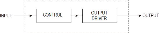
The "real world" input and output conditions of the system are shown as arrows entering, and leaving, the systems diagram.
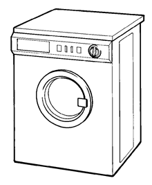 A product which has a fairly complicated control system is an automated washing machine.
A simplified systems diagram of a washing machine is shown below.
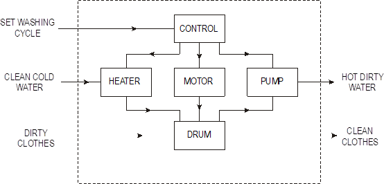
The function of the washing machine is to process dirty clothes to produce clean clothes. This is clearly represented within the systems diagram.
At the simplest level a control system can process an input condition to produce a specified output.
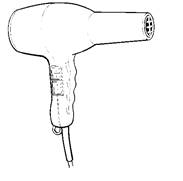
A good example of this type of system is a hand-held electric hairdryer. The heating element and fan motor are switched on when the appropriate switches are held down.
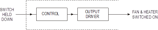
This is an example of Open Loop Control, where an input is processed to produce an output. With the hairdryer example the heater and fan motor are held on until the switches are released. The air being blown out of the hairdryer is not temperature monitored or adjusted - the air is simply just blown out at whatever temperature the heater is capable of achieving.
 Closed Loop Control
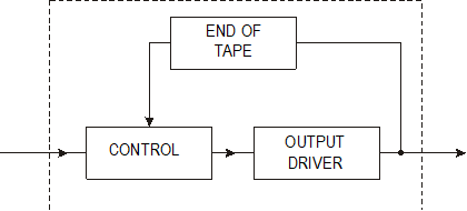
Closed loop control systems are capable of making decisions and adjusting their performance to suit changing output conditions.
A personal cassette player is capable of detecting the end of the tape and switching the motor off, hence protecting the tape from snapping (or the motor burning out).
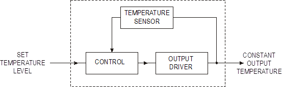
A heating control system can be represented by the following systems diagram.
However when an op-amp is used in a control system it is usual to draw a control diagram instead.
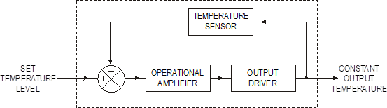
The control diagram breaks the generalised 'control' subsystem of the systems diagram into more specific blocks.
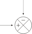
The error-detection symbol is also used to indicate that the control involves two signals. The feedback signal is connected to the negative symbol to indicate the use of negative feedback.
The purpose of closed loop control is to ensure that the output is maintained, as closely as possible, to the desired output level. In the case of a central heating system, a graph of the temperature in a room might appear as in the graph below.
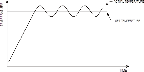
As can be seen from the graph, the control system is constantly trying to pull the temperature of the room back towards the set temperature level by reducing the error. This type of control uses negative feedback to reduce the error.
The opposite effect can be created by reinforcing the error, as can sometimes happen with public address systems when the microphone is held too close to the speakers. A sound is picked up by the microphone, amplified, and then output through the speaker. The amplified sound is then picked up, re-amplified and so on. The net result is a high pitch sound, which can be represented by the graph below.
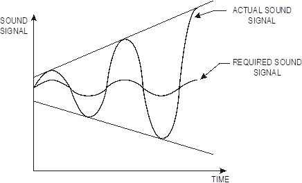
This is an example of positive feedback. Although positive feedback does have some useful applications, negative feedback is far more widely used in control systems.
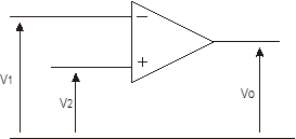
Many control systems involve processing analogue signals such as heat, light and movement. Therefore analogue closed loop control systems require analogue processing devices such as the operational amplifier (op-amp).
One of the most common control applications involves using the op-amp as a comparator. In it's simplest form a comparator just compares two voltage signals, V1 and V2. If V1 is higher than V2 the output, Vo, is 'low', if V1 is lower than V2 the output is 'high'
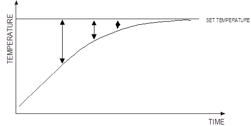
The main problem with two state control systems is that there is a time 'lag' built into their operation. This means that the desired output state is never actually reached.
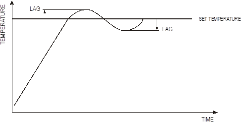
The graph of the temperature control system built in assignment 1 clearly shows the effect of lag.
When the reference level ("set temperature") is reached the heating system will continue to heat the room for a short period until the heating element cools down. This raises the temperature in the room above the set or desired temperature level. When the temperature in the room cools down to the reference level the heating system will be switched on. Whilst the heating element is reaching its operating temperature the room continues to cool below the reference level.
Whilst in heating systems the presence of lag does not present a problem, and in fact presents some advantages, in many other applications the inaccuracy of this form of control is not acceptable.
Proportional closed loop control systems are applied as a means of proving a more accurate form of analogue closed loop control. The operation of proportional control is based around the op-amp configured as a difference amplifier.
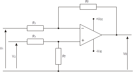
The difference amplifier amplifies the difference between the reference level and the feedback signal. Therefore if there is a large error there will be a larger output signal than when there is a small error. This help prevents the 'overshoot' and 'time lags' seen in the comparator based systems.
As the actual temperature rises, and starts to approach the set temperature, then the difference between V2 and V1 starts to reduce, so Vout from the Difference amp also starts to reduce, which in turn reduces the heat given out by the heater, so the actual temperature slow approaches the set temperature with no lag.
Think about the lift!!!!
Positional Control
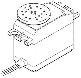
A good example of positional control is the model servo motor commonly found in radio-control cars and aeroplanes.
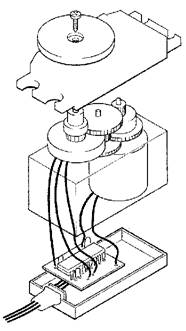
The servo contains a motor, gearbox, feedback potentiometer and electronic control circuit on a small printed circuit board.
The feedback potentiometer is directly connected to the output shaft. Therefore, when the motor spins, the output shaft is turned slowly by the gearbox, which in turn moves the potentiometer. Naturally movement of the output shaft is restricted to 180º as the potentiometer cannot spin continuously.
The control diagram for the servo is shown below.
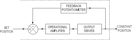
Note how the feedback signal from the feedback potentiometer is fed into the negative symbol of the control diagram, indicating negative feedback.
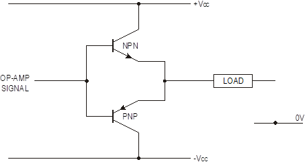 An important element in producing positional control, such as that required in the servo, is a dual rail push-pull follower analogue driver circuit, that allows the motor to spin in both directions. The op-amp cannot source sufficient current to drive most output components, and so the dual rail push-pull follower is required to drive the output components.
The dual rail push-pull follower is based around a two transistor circuit as shown below.
Circuit diagram
A +voltage here would switch on the npn, a –voltage here would switch on the pnp
The error is actually the difference between V2 and V1
Motor can spin clockwise or anti clockwise because a push pull motor driver is used.
If only one transistor is used it means the motor can only turn in one direction
Mechanical link to physically move the “actual” potentiometer
You would set the desired position here, creating an “error”
Source: http://www.earlstonhigh.scotborders.sch.uk/learningzone/technical/Revision%20Notes/HTS%20Revision%20notes/2-1&2%20Course%20notes.doc
Web site to visit: http://www.earlstonhigh.scotborders.sch.uk
Author of the text: indicated on the source document of the above text
If you are the author of the text above and you not agree to share your knowledge for teaching, research, scholarship (for fair use as indicated in the United States copyrigh low) please send us an e-mail and we will remove your text quickly. Fair use is a limitation and exception to the exclusive right granted by copyright law to the author of a creative work. In United States copyright law, fair use is a doctrine that permits limited use of copyrighted material without acquiring permission from the rights holders. Examples of fair use include commentary, search engines, criticism, news reporting, research, teaching, library archiving and scholarship. It provides for the legal, unlicensed citation or incorporation of copyrighted material in another author's work under a four-factor balancing test. (source: http://en.wikipedia.org/wiki/Fair_use)
The information of medicine and health contained in the site are of a general nature and purpose which is purely informative and for this reason may not replace in any case, the council of a doctor or a qualified entity legally to the profession.
The texts are the property of their respective authors and we thank them for giving us the opportunity to share for free to students, teachers and users of the Web their texts will used only for illustrative educational and scientific purposes only.
All the information in our site are given for nonprofit educational purposes