
UNIT VI: Basic Dimensioning Skills
Competency: 006.00
Demonstrate basic dimensioning techniques.
Objective: 006.01
Identify the accepted standards for mechanical dimensioning practices.
Introduction: The purpose of this unit is to introduce students to basic dimensioning techniques related to technical drawing. The previous units were mainly focused on describing the shape of objects. This unit will focus on describing the size and location of features. Standards for dimensioning technique, dimension placement, and general rules for dimensioning will be covered per Dimensioning and Tolerancing, ASME Y14.5M-1994. Standards for architectural dimensioning are to be covered in Architectural Drafting II.
Although most of this unit focuses on dimensioning technique (how dimensions should look on a drawing), students should be introduced to methods for determining the critical dimensions for a part. Since most objects exist within the context of an assembly, it is recommended that teachers make the students aware of how the part functions within the assembly before dimensioning the drawing.
R1(192-220):R2(230-244)
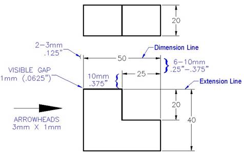
Identify the following standard practices for dimensioning:
UNIT VI: Basic Dimensioning Skills
Competency: 006.00
Demonstrate basic dimensioning techniques.
Objective: 006.02
Explain the procedures for dimensioning mechanical drawings.
R1(192-220):R2(230-244)
UNIT VI: Basic Dimensioning Skills
Competency: 006.00
Demonstrate basic dimensioning techniques.
Objective: 006.03
Construct dimensions on an engineering drawing.
Requirements: Each student is required to apply basic dimensioning techniques to a drawing.
1. Using the drafting equipment provided, give all of the dimensions and notes required to describe the object’s size and features.
2. The drawing is produced at a scale of 1:1 (full size).
3. Use decimal inches for all measurements. Give dimensions to two (2) decimal places.
4. Use accepted drafting standards for lines and freehand lettering.
5. Letter your name, problem number (006.03.001), scale, and date in the title block.
6. Time Limit = 60 minutes.
Assessment: The dimensioned drawing should be evaluated based on the following criteria:
Dimensioning concepts and techniques 50 points
Accuracy 25 points
Line weight, technique and neatness 20 points
Lettering 5 points
Rubric for BASIC DIMENSIONING SKILLS – Board drawing
Construct dimensions on an engineering drawing - 006.03
Dimensioning concepts and techniques
Numerous dimensions are missing. Numerous dimensions are duplicated or are not placed where shape is best shown. Arrowheads are missing. Dimensions are not grouped or aligned. Dimensions are crowded. |
Some needed dimensions and/or notes are missing. There is some crowding of dimensional text. Some dimensions are not grouped or aligned. Some dimensions are given where the shape was not best shown. |
Necessary dimensions & notes to manufacture the part are given. Dimensions given where shape is best shown. Dimensions are grouped and aligned. Unnecessary dimensions have been avoided. Shortest dimensions are placed closest to the object. Dimensions not crowded. Understanding of the rules for dimension placement should be clearly evident. |
Total |
0-35 points |
36-45 points |
46-50 points |
|
Accuracy
Numerous errors in measurements. Inappropriate scale used. |
Some errors in measurement. |
When measured, the sizes of features and their locations closely agree with the given problem. Scale is correct. |
Total |
0-17 points |
18-23 points |
24-25 points |
|
Line weight/technique/neatness
Line weights are not uniform. ANSI standards for thickness and darkness not followed. Poor spacing of dimension lines and/or extension line distances past arrowheads. Rules for leader line placement not followed. Poor gaping of extension lines. Size/formation of arrowheads not acceptable. |
Some lines are not uniform. Some lines do not meet ANSI standards. Arrowheads are poorly formed. |
Line quality is neat, clean, well-formed, and meets ANSI standards for thickness, darkness, and coding. Correct practices for center, dimension, extension and leader lines are followed. |
Total |
0-14 points |
15-18 points |
19-20 points |
|
Lettering
Letter height, thickness, and spacing are not uniform. Letters are not uniformly vertical or inclined. Several spelling errors. |
Some letters are not uniform in height, thickness, and spacing. Some letters are not uniformly vertical or inclined. No more than one spelling error. |
Lettering is neat, uniform, and correctly formed and spaced. Spelling is correct. All required information is provided. |
Total |
0 points |
3 points |
5 points |
|
Total Score
Rubric for BASIC DIMENSIONING SKILLS using CAD
Apply simple dimensioning to an engineering drawing - 006.03
Dimensioning concepts and techniques
Numerous dimensions are missing. Numerous dimensions are duplicated or are not placed where shape is best shown. Arrowheads are missing. Dimensions are not grouped or aligned. Dimensions are crowded. |
Some needed dimensions and/or notes are missing. There is some crowding of dimensional text. Some dimensions are not grouped or aligned. Some dimensions are given where the shape was not best shown. |
Dimensions and notes necessary to manufacture the part are given. Dimensions given where shape is best shown. Dimensions are grouped and aligned. Unnecessary dimensions have been avoided. Shortest dimensions are placed closest to the object. Dimensions are not crowded. Understanding of the rules for dimension placement should be clearly evident. |
Total |
0-44 points |
45-54 points |
55-60 points |
|
Accuracy
More than 2 dimension values do not agree with actual sizes on the part. |
One or two dimension values do not agree with actual sizes on the part. |
When measured, the sizes of features and their locations agree with the given problem. Drawing demonstrates an obvious use of object snaps. |
Total |
0-14 points |
15-18 points |
19-20 points |
|
Dimension, Extension, Center, and Leader Lines
ANSI standards for coding not followed. Poor spacing of dimension lines. Rules for leader line placement not followed. Poor gaping of extension lines. |
Some lines do not meet ANSI standards. Visible gaps not included on some extension lines. Some dimension lines not spaced properly. |
Lines meet ANSI standards for coding. Correct practices for center, dimension, extension and leader lines are followed. |
Total |
0-10 points |
11-13 points |
14-15 points |
|
Dimensioning Text and Notes
Text style and size does not meet accepted standards. More than one spelling error. |
No more than one spelling error. |
Text style and size meets accepted standards. Spelling is correct. |
Total |
0 points |
3 points |
5 points |
|
Total Score
AUTHENTIC ASSESSMENT: Product Development
Basic Dimensioning Skills Project Assessment
Source: https://www.quia.com/files/quia/users/mhill07/601/unit-6.doc
Web site to visit: https://www.quia.com
Author of the text: indicated on the source document of the above text
If you are the author of the text above and you not agree to share your knowledge for teaching, research, scholarship (for fair use as indicated in the United States copyrigh low) please send us an e-mail and we will remove your text quickly. Fair use is a limitation and exception to the exclusive right granted by copyright law to the author of a creative work. In United States copyright law, fair use is a doctrine that permits limited use of copyrighted material without acquiring permission from the rights holders. Examples of fair use include commentary, search engines, criticism, news reporting, research, teaching, library archiving and scholarship. It provides for the legal, unlicensed citation or incorporation of copyrighted material in another author's work under a four-factor balancing test. (source: http://en.wikipedia.org/wiki/Fair_use)
The information of medicine and health contained in the site are of a general nature and purpose which is purely informative and for this reason may not replace in any case, the council of a doctor or a qualified entity legally to the profession.
The texts are the property of their respective authors and we thank them for giving us the opportunity to share for free to students, teachers and users of the Web their texts will used only for illustrative educational and scientific purposes only.
All the information in our site are given for nonprofit educational purposes