Example: ![]() Circuit symbol:
Circuit symbol: ![]()
Diodes allow electricity to flow in only one direction. The arrow of the circuit symbol shows the direction in which the current can flow. Diodes are the electrical version of a valve and early diodes were actually called valves.
 Forward Voltage Drop
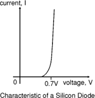
Electricity uses up a little energy pushing its way through the diode, rather like a person pushing through a door with a spring. This means that there is a small voltage across a conducting diode, it is called the forward voltage drop and is about 0.7V for all normal diodes, which are made from silicon. The forward voltage drop of a diode is almost constant whatever the current passing through the diode so they have a very steep characteristic (current-voltage graph).
When a reverse voltage is applied a perfect diode does not conduct, but all real diodes leak a very tiny current of a few µA or less. This can be ignored in most circuits because it will be very much smaller than the current flowing in the forward direction. However, all diodes have a maximum reverse voltage (usually 50V or more) and if this is exceeded the diode will fail and pass a large current in the reverse direction, this is called breakdown.
Ordinary diodes can be split into two types: Signal diodes, which pass small currents of 100mA or less, and Rectifier diodes, which can pass large currents. In addition there are LEDs (which have their own page) and Zener diodes (at the bottom of this page).
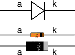 Diodes must be connected the correct way round, the diagram may be labelled a or + for anode and k or - for cathode (yes, it really is k, not c, for cathode!). A line painted on the body marks the cathode. Diodes are labelled with their code in small print, you may need a magnifying glass to read this on small signal diodes!
Small signal diodes can be damaged by heat when soldering, but the risk is small unless you are using a germanium diode (codes beginning OA...) in which case you should use a heat sink clipped to the lead between the joint and the diode body. A standard crocodile clip can be used as a heat sink.
Rectifier diodes are quite robust and no special precautions are needed for soldering them.
You can use a multimeter or a simple tester (battery, resistor and LED) to check that a diode conducts in one direction but not the other. A lamp may be used to test a rectifier diode, but do NOT use a lamp to test a signal diode because the large current passed by the lamp will destroy the diode!
Signal diodes are used to process information (electrical signals) in circuits, so they are only required to pass small currents of up to 100mA.
General-purpose signal diodes such as the 1N4148 are made from silicon and have a forward voltage drop of 0.7V.
Germanium diodes such as the OA90 have a lower forward voltage drop of 0.2V and this makes them suitable to use in radio circuits as detectors, which extract the audio signal from the weak radio signal.
For general use, where the size of the forward voltage drop is less important, silicon diodes are better because they are less easily damaged by heat when soldering, they have a lower resistance when conducting, and they have very low leakage currents when a reverse voltage is applied.
Signal diodes are also used with relays to protect transistors and integrated 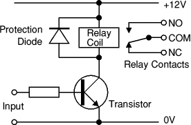 circuits from the brief high voltage produced when the relay coil is switched off. The diagram shows how a protection diode is connected across the relay coil, note that the diode is connected 'backwards' so that it will normally NOT conduct. Conduction only occurs when the relay coil is switched off, at this moment current tries to continue flowing through the coil and it is harmlessly diverted through the diode. Without the diode no current could flow and the coil would produce a damaging high voltage 'spike' in its attempt to keep the current flowing.
Diode |
Maximum |
Maximum |
1N4001 |
1A |
50V |
1N4002 |
1A |
100V |
1N4007 |
1A |
1000V |
1N5401 |
3A |
100V |
1N5408 |
3A |
1000V |
Rectifier diodes are used in power supplies to convert alternating current (AC) to direct current (DC), a process called rectification. They are also used elsewhere in circuits where a large current must pass through the diode.
All rectifier diodes are made from silicon and therefore have a forward voltage drop of 0.7V. The table shows maximum current and maximum reverse voltage
for some popular rectifier diodes. The 1N4001 is suitable for most low voltage circuits with a current of less than 1A.
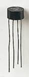
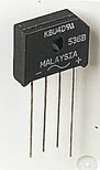
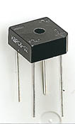
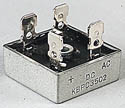
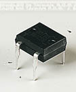
 There are several ways of connecting diodes to make a rectifier to convert AC to DC. The bridge rectifier is one of them and it is available in special packages containing the four diodes required. Bridge rectifiers are rated by their maximum current and maximum reverse voltage. They have four leads or terminals: the two DC outputs are labelled + and -, the two AC inputs are labelled
 ![]() .
.
The diagram shows the operation of a bridge rectifier as it converts AC to DC. Notice how alternate pairs of diodes conduct.
 |
|
|
|
|
Various types of Bridge Rectifiers |
||||
Example: ![]() Circuit symbol:
Circuit symbol: ![]()
a = anode, k = cathode
Zener diodes are used to maintain a fixed voltage. They are designed to 'breakdown' in a reliable and non-destructive way so that they can be used in reverse to maintain a fixed voltage across their terminals. The diagram 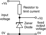 shows how they are connected, with a resistor in series to limit the current.
Zener diodes can be distinguished from ordinary diodes by their code and breakdown voltage, which are printed on them. Zener diode codes begin BZX... or BZY... Their breakdown voltage is printed with V in place of a decimal point, so 4V7 means 4.7V for example.
Zener diodes are rated by their breakdown voltage and maximum power:
Source: http://folders.sirthomasboughey.staffs.sch.uk/easylink/intranet/stbh/files/staff1/Diodes.doc
Web site to visit: http://folders.sirthomasboughey.staffs.sch.uk/
Author of the text: indicated on the source document of the above text
If you are the author of the text above and you not agree to share your knowledge for teaching, research, scholarship (for fair use as indicated in the United States copyrigh low) please send us an e-mail and we will remove your text quickly. Fair use is a limitation and exception to the exclusive right granted by copyright law to the author of a creative work. In United States copyright law, fair use is a doctrine that permits limited use of copyrighted material without acquiring permission from the rights holders. Examples of fair use include commentary, search engines, criticism, news reporting, research, teaching, library archiving and scholarship. It provides for the legal, unlicensed citation or incorporation of copyrighted material in another author's work under a four-factor balancing test. (source: http://en.wikipedia.org/wiki/Fair_use)
The information of medicine and health contained in the site are of a general nature and purpose which is purely informative and for this reason may not replace in any case, the council of a doctor or a qualified entity legally to the profession.
The texts are the property of their respective authors and we thank them for giving us the opportunity to share for free to students, teachers and users of the Web their texts will used only for illustrative educational and scientific purposes only.
All the information in our site are given for nonprofit educational purposes