
Figure 1 shows the type of lettering which should be used in technical drawings. Lettering should be simple, so that it can be easily read. As mentioned above, the height of letters should vary according to the size of drawing sheet in use. Notes and dimension lettering and figures should be drawn at a lower height than title block lettering. For example, on A4 sheets 3 mm high notes and dimension figures would be suitable, on an A2 sheet a height of 5 or 6 mm would be better.
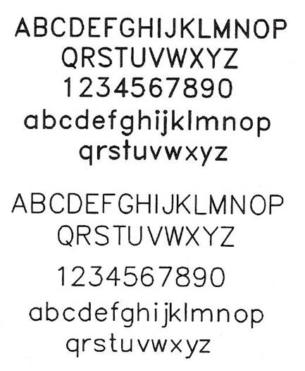
Figure 1 - Types of Lettering for Technical Drawings
Figure 2 shows some of the types of lines. Note that the lines of the outline of drawings should be thicker than other lines. This makes the outline stand out clearly against the other details in your drawings.
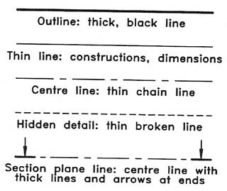
Figure 2 - Types of Line for Technical Drawings
In title blocks, features such as names, article titles, etc. are usually printed in capital letters. Their height will vary according to the size of the drawing sheet in use. Suggested heights are 6 mm for A4 sheets, 8 mm for A3 sheets and 10 mm for A2 sheets.
Figure 3 shows a type of sheet layout, which may be found in use by engineering companies. The sheets will be pre-printed so that draughtsmen can start working on the sheet without having to add details such as those shown in the title block. Note also the set of reference numbers around the margins of this sheet - anyone using the drawing can indicate any part by reference to the marginal letters and figures.
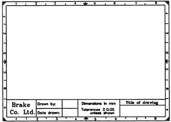
Figure 3 - Example of a Drawing Sheet Layout such as would be used in an Engineering Company
The following notes are meant as a guide to the method of applying the more commonly used welding symbols relating to the simpler types of welded joints on engineering drawings. Where complex joints involve multiple welds it is often easier to detail such constructions on separate drawing sheets.
Each type of weld is characterised by a symbol given in Table 1. Note that the symbol is representative of the shape of the weld, or the edge preparation, but does not indicate any particular welding process and does not specify either the number of runs to be deposited or whether or not a root gap or backing material is to be used. These details would be provided on a welding procedure schedule for the particular job.
It may be necessary to specify the shape of the weld surface on the drawing as flat, convex or concave and a supplementary symbol is then added to the elementary symbol.
A joint may also be made with one type of weld on a particular surface and another type of weld on the back and in this case elementary symbols representing each type of weld used are added together.
A welding symbol is applied to a drawing by using a reference line and an arrow line. The reference line should be drawn parallel to the bottom edge of the drawing sheet and the arrow line forms an angle with the reference line. The side of the joint nearer the arrowhead is known as the 'arrow side' and the remote side as the 'other side'.
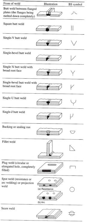
Table 1 - Elementary Weld Symbols
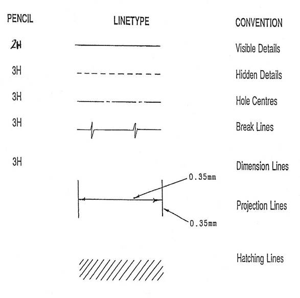
Figure 4 - Standards and Conventions
Many technical drawings will be drawn to scales in which the drawing is either smaller or larger than it’s correct full-size. When drawing to a scale all parts of the drawing are reduced or enlarged by the scale factor. Common scales in use with the metric system of measurement are:
Drawing 1 (Figure 5) - Constructing a scale of 1:5. Each 1 mm on the drawing represents 5 mm on the item being drawn.
Note: two examples of taking scaled measurements from the scale are shown in Figure 5. Examine the scale and you will understand why the scale is numbered with 0 being at the first division point along AB.
Drawing 2 (Figure 5) - Constructing a scale of 60 mm represents 1 metre.
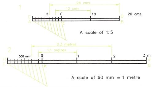
Figure 5 - Drawing Scales
Diagonal scales are used where great accuracy is required. If accurately drawn, measurement down to millimetres in scales, such as 1:2 or 1:5, can be made with the aid of these scales. The scale to be constructed in this example is one of 1:2.5 to read in millimetres up to 300 mm.
Stage 1- To a scale of 1:2.5, 100 mm is represented by 40 mm.
Stage 2
Stage 3
Note: the bottom drawing of Figure 6 shows how measurements greater than 100 mm are taken from a diagonal scale. The sequence is:
For preparing the layouts for orthographic drawings and for the necessary preparation work when square grid papers are available, a good tip is to start learning how to draw freehand sketches on grid papers. Such grid papers can be purchased in A4 or A3 sheets with the grid lines printed in green or blue - either square grids or isometric grids are available. The spacing of the grid lines is either at 10 mm intervals or at 5 mm intervals. However, when you have gained sufficient skill in freehand drawing with the aid of grid papers, it is best to then sketch on plain paper without the grid lines. The examples given in this book are for freehand sketching on either the lines of orthographic projection or isometric drawing.
An example of a freehand drawing of a pedestal mounting as preparation for the layout of the drawing before constructing the views of an orthographic projection are shown in three examples - Figure 7 on an A3 sheet of 10 mm square grid paper, Figure 8 on a smaller sheet of grid paper and Figure 9 on plain paper without a grid. Figure 10 shows a freehand isometric drawing on isometric grid paper with the grid at 10 mm spacing. Figure 11 is a similar freehand drawing on isometric lines on plain paper without grid lines.
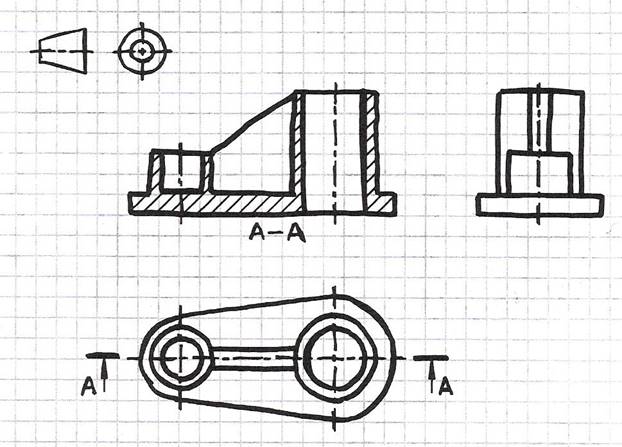
Figure 7 - Freehand Drawing on an A3 Sheet of 10mm Square Grid Paper
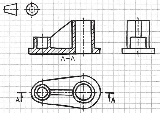
Figure 8 - Example of a Freehand Drawing on 10mm Square Grid Paper
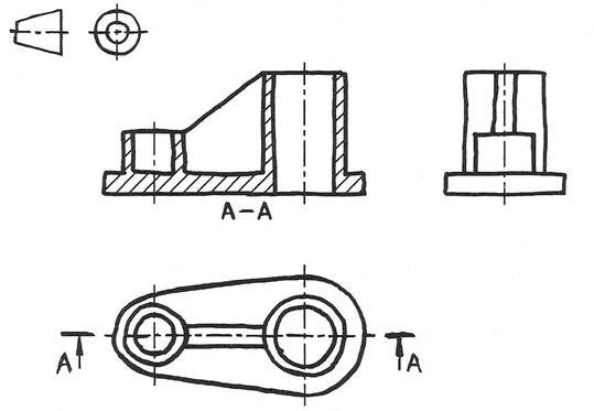
Figure 9 - Freehand Drawing of an Orthographic Projection on Plain Paper without Grid Lines
A single-part drawing should supply the complete detailed information to enable a component to be manufactured without reference to other sources. It should completely define shape or form and size, and should contain a specification. The number of views required depends on the degree of complexity of the component. The drawing must be fully dimensioned, including tolerances where necessary, to show all sizes and locations of the various features. The specification for the part includes information relating to the material used and possible heat-treatment required, and notes regarding finish. The finish may apply to particular surfaces only, and may be obtained by using special machining operations or, for example, by plating, painting, or enamelling. Figure 12, Figure 13 and Figure 14 show typical single-part drawings.
An alternative to a single-part drawing is to collect several small details relating to the same assembly and group them together on the same drawing sheet. In practice, grouping in this manner may be satisfactory provided all the parts are made in the same department, but it can be inconvenient where, for example, pressed parts are drawn with turned components or sheet-metal fabrications.
More than one drawing may also be made for the same component. Consider a sand-cast bracket. Before the bracket is machined, it needs to be cast; and before casting, a pattern needs to be produced by a pattern maker. It may therefore be desirable to produce a drawing for the pattern maker, which includes the various machining allowances, and then produce a separate drawing for the benefit of the machinist, which shows only dimensions relating to the surfaces to be machined and the size of the finished part. The two drawings would each have only parts of the specification, which suited one particular manufacturing process.
Figure 15 shows a typical collective single-part drawing for a. rivet. The drawing covers 20 rivets similar in every respect except length; in the example given, the part number for a 30 mm rivet is 5123/13. This type of drawing can also be used where, for example, one or two dimensions on a component (which are referred to on the drawing as Aand B) are variable, all others being standard. For a particular application, the draughtsman would insert the appropriate value of dimensions Aand Bin a table, then add a new suffix to the part number. This type of drawing can generally be used for basically similar parts.
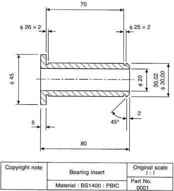
Figure 12 - Bearing Insert
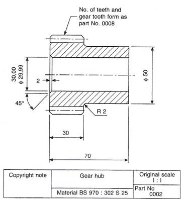
Figure 13 - Gear Hub
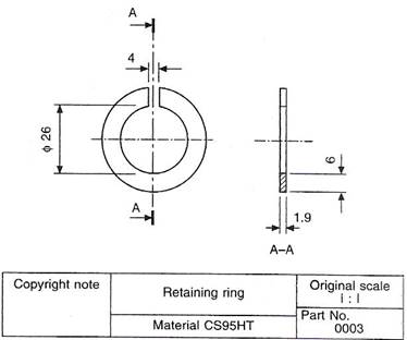
Figure 14 - Retaining Ring
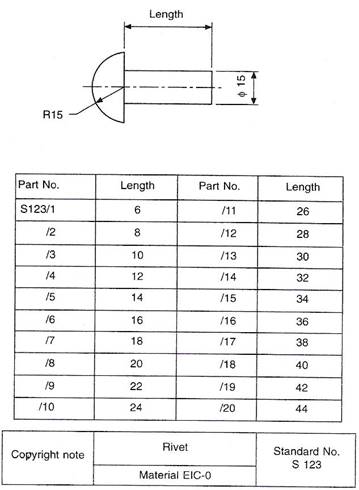
Figure 15 - Collective Single-Part Drawing of a Rivet
Machines and mechanisms consist of numerous parts, and a drawing, which shows the complete product with all its components in their correct physical relationship, is known as an assembly drawing. A drawing that gives a small part of the whole assembly is known as a sub-assembly drawing. A sub-assembly may in fact be a complete unit in itself; for example, a drawing of a clutch could be considered as a sub-assembly of a drawing showing a complete automobile engine. The amount of information given on an assembly drawing will vary considerably with the product and its size and complexity.
If the assembly is relatively small, information that might be given includes a parts list. The parts list, as the name suggests, lists the components, which are numbered. Numbers in 'balloons' with leader lines indicate the position of the component on the drawing (see Figure 16). The parts list will also contain information regarding the quantity required of each component for the assembly, its individual single-part drawing number, and possibly its material. Parts lists are not standard items, and their contents vary from one drawing office to another.
The assembly drawing may also give other information, including overall dimensions of size, details of bolt sizes and centres where fixings are necessary, weights required for shipping purposes, operating details and instructions, and also, perhaps, some data regarding the design characteristics.
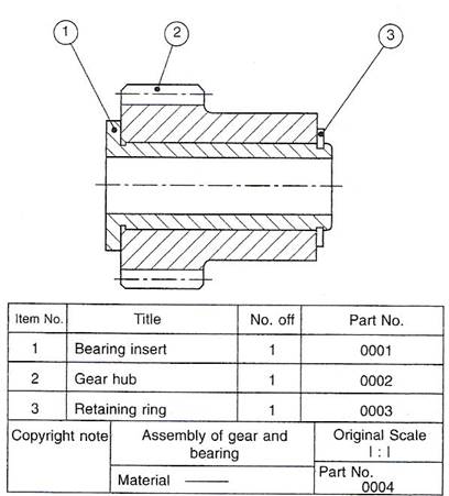
Figure 16 - Assembly Drawing of Gear and Bearing
This type of drawing is used where a range of products, which are similar in appearance but differing in size is manufactured and assembled. Figure 17 shows a nut-and-bolt fastening used to secure plates of different combined thickness; the nut is standard, but the bolts are of different lengths. The accompanying table is used to relate the various assemblies with different part numbers.
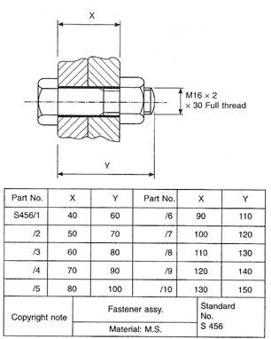
Figure 17 - Typical Collective Assembly Drawing of a Nut with Bolts of Various Lengths
Most original designs are planned in the drawing office where existing or known information is collected and used to prepare a provisional layout drawing before further detailed design work can proceed. This type of drawing is of a preliminary nature and subject to much modification so that the designer can collect his thoughts together. The drawing can be true to scale or possibly enlargements or reductions in scale depending on the size of the finished product or scheme, and is essentially a planning exercise. They are useful in order to discuss proposals with prospective customers or design teams at a time when the final product is by no means certain, and should be regarded as part of the design process.
Provisional layout drawings may also be prepared for use with tenders for proposed work where the detailed design will be performed at a later date when a contract has been negotiated, the company being confident that it can ultimately design and manufacture the end product. This confidence will be due to experience gained in similar schemes undertaken previously.
It is sometimes convenient to illustrate details with their assembly drawing on the same sheet. This practice is particularly suited to small 'one-off' or limited-production-run assemblies. It not only reduces the actual number of drawings, but also the drawing-office time spent in scheduling and printing. Figure 18 shows a simple application of an assembly on his type.
Generally a pictorial type of projection is used, so that each part will be shown in three dimensions. Exploded views are invaluable when undertaking servicing and maintenance work on all forms of plant and appliances. Car manuals and do-it-yourself assembly kits use such drawings, and these are easily understood. As well as an aid to construction, an exploded assembly drawing suitably numbered can also be of assistance in the ordering of spare parts; components are more easily recognisable in a pictorial projection, especially by people without training in the reading of technical drawings.
Simplified draughting conventions have been devised to reduce the time spent drawing and detailing symmetrical components and repeated parts. Figure 19 shows a gasket, which is symmetrical about the horizontal centre line. A detail drawing indicating the line of symmetry and half of the gasket is shown in Figure 19, and this is sufficiently clear for the part to be manufactured.
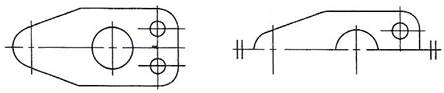
Figure 19 - Symmetrical Gasket and Half Gasket
If both halves are similar except for a small detail, then the half that contains the exception is shown with an explanatory note to that effect, and a typical example is illustrated in Figure 20.
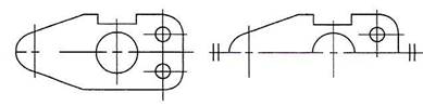
Figure 20 - When Dimensioning Add Drawing Note 'Slot on one Side only'
A joint-ring is shown in Fig. 7.10, which is symmetrical about two axes of symmetry. Both axes are shown in the detail, and a quarter view of the joint-ring is sufficient for the part to be made.
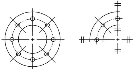
Figure 21 - Symmetrical Joint Ring
The practice referred to above is not restricted to flat thin components, and Figure 22 gives a typical detail of a straight lever with a central pivot in part section. Half the lever is shown, since the component is symmetrical, and a partial view is added and drawn to an enlarged scale to clarify the shape of the boss and leave adequate space for dimensioning.
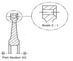
Figure 22 - Part of a Lever Detail Drawing Symmetrical about the Horizontal Axis
Repeated information also need not be drawn in full; for example, to detail the peg-board in Figure 23 all that is required is to draw one hole, quoting its size and fixing the centres of all the others.
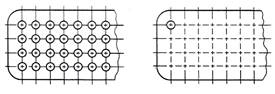
Figure 23 - Peg-Board
Similarly, Figure 24 shows a gauze filter. Rather than draw the gauze over the complete surface area, only a small portion is sufficient to indicate the type of pattern required.
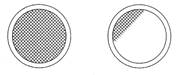
Figure 24 - Gauze Filter
Knurled screws are shown in Figure 25 to illustrate the accepted conventions for straight and diamond knurling.
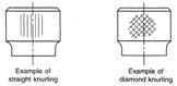
Figure 25 - Knurled Screws
The draughtsman must be able to appreciate the significance of every line on a machine drawing. He must also understand the basic terminology and vocabulary used in conjunction with machine drawings.
Machine drawings of components can involve any of the geometrical principles and constructions described in this book and in addition the accepted drawing standards covered by BS 8888.
Figure 26 illustrates many features found on machine drawings and the notes that follow give additional explanations and revision comments.
In order to shorten drawing notes we often use abbreviations, and the following list gives a selection of commonly used terms in accordance with BS 8888.
Questions on Background Notes – Module 6.Unit 3
1. In relation to line type and convention in technical drawing sketch:
2. In relation to drawing scales what does the Word/Numbering Scale 1:5 mean?
4. Give the abbreviations for the following terms:
Source: http://local.ecollege.ie/Content/APPRENTICE/liu/metalfab_notes/module6/Standard%20Conventions_M6_U3.doc
Web site to visit: http://local.ecollege.ie/
Author of the text: indicated on the source document of the above text
If you are the author of the text above and you not agree to share your knowledge for teaching, research, scholarship (for fair use as indicated in the United States copyrigh low) please send us an e-mail and we will remove your text quickly. Fair use is a limitation and exception to the exclusive right granted by copyright law to the author of a creative work. In United States copyright law, fair use is a doctrine that permits limited use of copyrighted material without acquiring permission from the rights holders. Examples of fair use include commentary, search engines, criticism, news reporting, research, teaching, library archiving and scholarship. It provides for the legal, unlicensed citation or incorporation of copyrighted material in another author's work under a four-factor balancing test. (source: http://en.wikipedia.org/wiki/Fair_use)
The information of medicine and health contained in the site are of a general nature and purpose which is purely informative and for this reason may not replace in any case, the council of a doctor or a qualified entity legally to the profession.
The texts are the property of their respective authors and we thank them for giving us the opportunity to share for free to students, teachers and users of the Web their texts will used only for illustrative educational and scientific purposes only.
All the information in our site are given for nonprofit educational purposes