
Failure analysis is the systemic study of the nature of various modes of material failure. Obviously, to prevent failure we need to understand it. Failure can have many definitions. For our purposes here we will consider failure to be separation of a part into two or more pieces.
Summary of various loading modes/corresponding failure modes:
Loading Mode |
Corresponding Failure mode |
static stresses at low T (<TReX ) |
Simple failure in either |
impact loading |
Impact failure in either |
fluxuating stresses |
fatigue failure |
static stresses at high T over long time periods |
creep and stress–rupture failure |
stresses applied in corrosive or adverse environments |
corrosion-fatigue failure |
stresses applied at surfaces in a shearing repetitive mode |
wear failure |
any combination of the above |
complex failure |
Additionally, loading modes can be characterized as being uniaxial (tension or compression), flexural (shear–bending), or torsional (shear–twisting). |
|
¥The two main types of failure modes are ductile or brittle:
Ductile Failure Mode
(preferred because there is warning)
Brittle Failure Mode
(usually catastrophic - very fast and no warning)
*a stable crack resists further extension unless more stress is applied. An unstable crack is one that will continue to grow without an increase in stress.
In general (although there are many exceptions):
Impact Fracture Testing
Tensile tests are inadequate to predict fracture behavior under certain conditions:
Under these conditions sometimes normally ductile metals fail in a brittle mode.
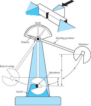
Impact tests were developed for these “bad” cases. The two most common are the Charpy Impact Energy test and the Izod Impact Energy test. Both these tests measure the material property of impact energy (or notch toughness) which is merely the energy absorbed by a standard notched specimen while it underwent loading that produced a rapid succession of elastic deformation, plastic deformation and finally fracture. This material property is correlated to the toughness - the area under the stress-strain curve. (The difference between the Izod and the Charpy test is the geometry of the notch.)
The material properties of impact energy and toughness are more “qualitative” than fracture toughness which was developed later in fracture mechanics. They are inadequate for design purposes; however, they do give some indication of how the material will respond.
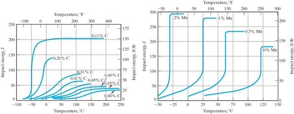
Ductile to Brittle Transition Temperature
The Impact Energy tests revealed that many materials with the bcc or hcp structures experience a transition from ductile to brittle failure modes at low temperatures. fcc materials do not. This ductile to brittle transition temperature is dependant on the material composition (steels with more carbon have higher Td®b) and the microstructure (smaller grain materials have lower Td®b).
Fatigue
is the failure of materials subjected to repetitive or cyclic stresses that can be much less than Sy.
Fatigue failure is thought to be responsible for 90% metal failures.
The fatigue stresses can be axial (T or C), flexural (bending), or torsional (twisting).
The repeated applications of loads create local plastic deformations which result in a flaw, usually at the material’s surface. The flaw grows into a crack which then starts to grow with every cycle of stress. Once the crack grows to a size that becomes unstable, failure occurs quickly. Failure from fatigue can be catastrophic, sudden and without warning. The fatigue fracture surface tends to be largely brittle-like, even for normally ductile materials.
Terms to quantify the stress applications:
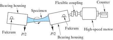
The RR Moore Test is the standard test used to quantify fatigue.
The test will produce S-N curves
where
S is the applied stress for complete reversed loading (the worst case) and
N is the number of cycles to failure
Note: There are actually lots of “scatter” in the data for these curves since fatigue life will depend on many variables:
The fatigue mechanism:
So once a material has a crack, the crack will inevitably grow under cyclic stresses and failure will result.
Fracture mechanics can be used to predict the “life” left. (i.e. the number of cycles left to failure.)
 Static Fatigue
Fatigue in metals results from microstructural damage generated by a mechanical mechanism: cyclic loading. The same phenomena is found in polymers.
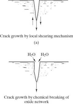
![]() Fatigue in ceramics and glasses results from microstructural damage generated by a different mechanism: chemical reactions.
Fatigue in ceramics and glasses results from microstructural damage generated by a different mechanism: chemical reactions.
Since there is no cyclic loading, this phenomena is called static fatigue. It occurs in a moist environment at room temperature. The mechanism is a chemical reaction of water with the silicate network that generates two Si-OH unit that are not bonded to each other, leaving a break in the silicate network.
Fracture Mechanics
is the theoretical and experimental analysis of the fracture of materials with pre-existing flaws.
This field allows quantification of the relationships between material properties, stress level, the presence of crack-producing flaws, and crack propagation mechanisms.
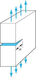
There are 3 modes of loading considered in Fracture Mechanics:
Mode I – tensile (shown here)
Mode II – shear
Mode III – torsional
Based on atomic bonding energies, the theoretical cohesive strength (fracture strength) of a material is on the order of E/10. However, the measured fracture strength of a brittle material is much lower. Why? The answer lies in the fact that there are small, microscopic flaws or cracks exist that act as stress raisers.
The same phenomena is observed for any material with a crack.
It will fail at stress levels below the expected strength for that material.
stress raisers
A stress raiser is anything that increases the nominal stress in a part, usually due to geometry. (Notches, keyways, corners, cracks, etc.)
stress concentration factor, Kt
This gives the factor by which the applied stress is multiplied to get the maximum stress at a stress raiser. Kt = sm / so Stress concentration factors can be looked up for many different stress raisers and many different geometries.
The Griffiths crack model predicted that the applied stress (so) is amplified or concentrated at the crack tip according to this equation:
sm = 2 so ![]()
So the stress concentration factor for a crack is: Kt = ![]() = 2
= 2 ![]()
Note: The stress concentration factors can be less in ductile materials because yielding leads to more uniform distribution of stress and a larger radius of curvature at the crack tip.
stress intensity factor, K
This is a parameter used in fracture mechanics that gives an indication of the material condition relative to the applied stress and the crack length:
K = Yso![]() (units: MPa
(units: MPa![]() or psi
or psi![]() )
)
where so is the applied stress
a is the crack length (= ½ crack length for an internal crack)
Y is a function of crack length, geometry and manner of loading (usually @ 1.0)
fracture toughness, KC
The fracture toughness is an important material property from the field of fracture mechanics.
It is the critical value of the stress intensity factor that causes failure.
Hence, it is a measure of the material’s resistance to brittle fracture when a crack is present. It can be thought of as the ductility of the material on a microscopic level. It will depend on temperature, strain rate and microstructure.
fracture toughness, KIC
The value for fracture toughness is usually given for mode I loading and plane strain.
Then it is called “kay-one-cee”.
plane strain
A state of stress induced in the material when the plate thickness >>>crack length
Generally plane strain applies if thickness > 2.5(KIC/sy )2
plane stress
The stress state for the case of a thin specimen. In this case KC will depend on the thickness.
stress -vs- strength is analogous to stress intensity factor -vs- fracture toughness
Life Calculations:
Consider crack length, a -vs- number of cycles of stress,
To get the life, Nf, for a particular value of a, integrate the power law equation between ao and af. ao is the value of the initial crack size and af can be found from the fracture toughness.
This will only be approximate since the power law behavior is not valid over the entire life.
Source: https://fog.ccsf.edu/~wkaufmyn/ENGN45/Course%20Handouts/Chap08_Failure.doc
Web site to visit: https://fog.ccsf.edu/
Author of the text: indicated on the source document of the above text
If you are the author of the text above and you not agree to share your knowledge for teaching, research, scholarship (for fair use as indicated in the United States copyrigh low) please send us an e-mail and we will remove your text quickly. Fair use is a limitation and exception to the exclusive right granted by copyright law to the author of a creative work. In United States copyright law, fair use is a doctrine that permits limited use of copyrighted material without acquiring permission from the rights holders. Examples of fair use include commentary, search engines, criticism, news reporting, research, teaching, library archiving and scholarship. It provides for the legal, unlicensed citation or incorporation of copyrighted material in another author's work under a four-factor balancing test. (source: http://en.wikipedia.org/wiki/Fair_use)
The information of medicine and health contained in the site are of a general nature and purpose which is purely informative and for this reason may not replace in any case, the council of a doctor or a qualified entity legally to the profession.
The texts are the property of their respective authors and we thank them for giving us the opportunity to share for free to students, teachers and users of the Web their texts will used only for illustrative educational and scientific purposes only.
All the information in our site are given for nonprofit educational purposes