Often, a three dimensional object must be represented with precision and clarity on a plane surface. Pictorial representations of a three-dimensional object on a plane are adequate only if the object is simple, however a different method of representation must be used for more complex objects – one that will show the true shapes of their surfaces.
By observing the shadows of objects cast by light sources, it can be seen that an object can be ‘projected’ onto a two-dimensional surface (i.e. a plane of projection) by projecting points of the object onto the surface and joining them in order.
Orthographic projection is a means of representing a three-dimensional object in two dimensions. It uses multiple views of an object, from points of view rotated about the objects centre through increments of 90 degrees. Equivalently, the views may be considered to be obtained by rotating the object about its centre through increments of 90 degrees.
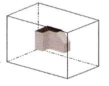
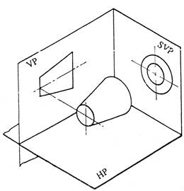
The views are positioned relative to each other according to either of two schemes: first-angle or third-angle projection. In each- the appearances of views may be thought of as being “projected” onto planes that form a transparent “box” around the object.
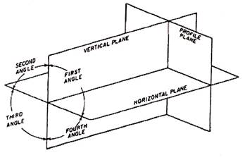
When drawing a number of views of an object, the object is viewed through a plane of projection from a point at infinity, thereby obtaining an accurate outline of the visible face of the object. However, the projection of one face will not provide an overall description of the object; other planes of projection must be used. Establishing an object’s true height, width and depth requires a front, top and side views, which are called the principal planes of projection. The three principal (or primary) planes of projection are known as the vertical, horizontal and profile planes. The angles formed between the horizontal and the vertical planes are called the first, second, third and fourth angles as shown in the diagram below. For practical purposes only the first and third angle is used.
Principal planes of projection.
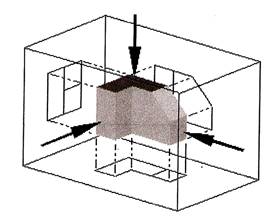
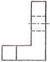
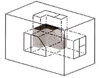
In first angle projection, each view of the object is projected in the direction (sense) of sight of the object, onto the interior walls of the box.
A two dimensional representation of the object is then created by “unfolding” the box, to view all the interior walls.
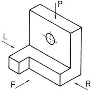
The pictorial drawing, see Fig. 1, indicates the shape of the component with a single view.
An orthographic drawing indicates the shape of a component by using a number of views each looking at a different face of the component. Usually, however, three views are shown in order to clarify internal and external detail:
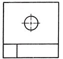
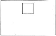
Fig. 2
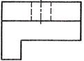
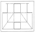
Fig. 3
View looking in direction of arrow R. |
|
|
View looking in direction of arrow L. |
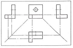
The separate views of the component are combined to form a complete orthographic drawing as shown below.
The front and side views are drawn in line with each other so that the side view may be “projected” from the front view and visa versa.
The plan view is drawn in line with and below the front view. In other words, the plan is projected from the front view.
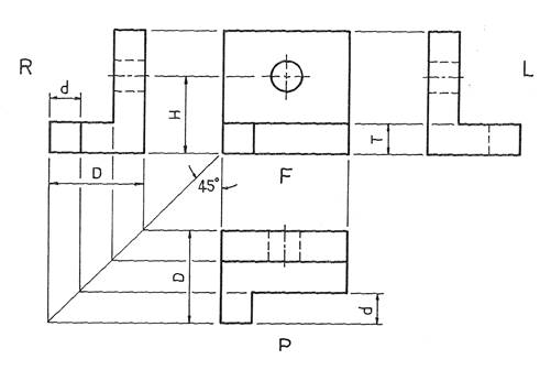
Points to note when making a drawing using first angle orthographic projection:
Note: Drawings should be read (or interpreted) by viewing from the R.H. side or bottom R.H. corner of the drawing.
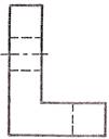
In third angle projection, each view of the object is projected opposite to the direction (sense) of sight of the object, onto the interior walls of the box.
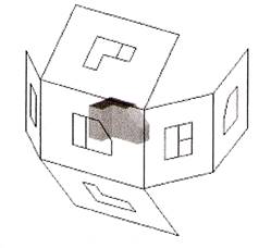
A two dimensional representation of the object is then created by “unfolding” the box, to view all the interior walls.
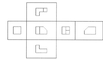
The term “third-angle” is used because, compared to “first-angle” projection, the directions of projection are rotated through two right angles about the object. Second-angle and fourth-angle projection also are defined, but do not result in useful images.
Third-angle projection is often considered to be more intuitive than first-angle projection.
While third-angle projections are prevalent in the USA and Canada, First-Angle projection is more popular in Europe and Asia.
Standard Symbols
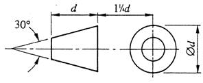
Recommended Proportions for symbols: The symbols for first and third angle are based on the frustum of a cone as shown.
Frustum of cone in the first quadrant: First-angle projection; View from the left appears on the right.
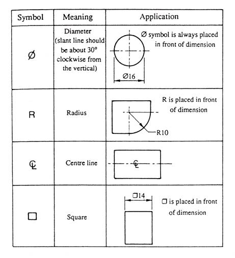
Some commonly used symbols and abbreviations.
An engineering drawing is a graphical language or an international language, and is one of the main forms of communication in the workshop or on site. In oral or written communication were the only means of communication when dealing with technical matters, misunderstandings could arise, particularly in relation to shape and size which could have serious implications for a company. Jobs fabricated and installed incorrectly could lead to wasted time and materials, loss of profits, bad customer relations, breach of contract and litigation. However, the universally accepted methods used in graphical communication through engineering drawings helps to eliminate many of the difficulties mentioned above by proper representation and layout of the job with all the details and information shown on the drawings. Mistakes can still be made, however, they are vastly reduced by good engineering drawing practice.
To ensure uniformity of interpretation the British Standards Institution have produced a booklet entitled BS 8888: 2004.
Drawing office personnel use an engineering drawing to transfer a mental picture of an object to the workshop or site. To avoid any confusion to the receiver the following rules should be followed.
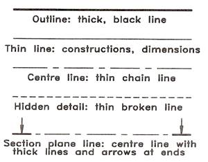
The types of line for engineering drawings recommended in the British Standards Institution in BS 8888: 2004. Two line thicknesses are recommended: thick 0.7mm wide and thin 0.3mm wide. For pencil drawings the recommendation can be interpreted as meaning that thick lines should be approximately twice as wide as thin lines.
The visible outlines of the object are drawn in continuous thick lines. They should be the most prominent lines on the drawing.
He hidden outlines of the object are represented by lines made up of short thin dashes. The dashes and the gaps between them must be consistent in length and approximately to the proportions as shown. At corners and tangent points of arcs, dashes should meet.
The continuous thin line is used for dimension lines, projection lines, leaders for notes, hatching or section-lining, the outlines of adjacent parts and revolved sections and fictitious outlines.
The limits of partial views and sections are shown by continuous irregular lines when the line is not an axis. These lines are thin and drawn freehand.
Centre lines and the extreme positions of moveable parts are shown by thin chain lines. These comprise of long dashes alternating with short dashes, not dots, proportioned approximately, as shown. The lengths of the dashes and their spacing may be extended for very long lines.
Cutting planes for sections are represented by chain lines, thick at their ends and at changes of directions, thin elsewhere.
Thick chain lines indicate surfaces which have to meet special requirements. The lengths of the parts of these lines and the spacing between them should be similar to those of thin chain lines.
All chain lines must begin and end with a long dash. Centre lines should extend beyond the feature to which they refer for a short distance only, unless required for dimensioning. They should not be drawn through the spaces between views and must not end at another line of the drawing. Also they must cross each other at solid parts of the lines.
Chain lines having angles formed in them should be drawn with long dashes meeting at the angles. Arcs should join at tangent points.
Arrowheads at the end of dimension lines must touch the projection lines and those at the end of leaders must touch another line on the drawing. They must be sharp, black, filled-in and about 3mm long.
The essential features of lettering on engineering drawings are legibility, uniformity and the ability to be produced rapidly. Legibility and speed are achieved by the use of block, single-stroke style which may be either upright or sloping. Students are recommended to use the upright style as it is easier to produce. Single-stroke lettering has all the strokes of uniform thickness, and each stroke is produced by one movement of the pencil. Capital letters are preferred to lower-case ones, being less congested and less likely to be misread when reduced in size on prints. Lower-case letters should, however, be used when they are part of a standard symbol, code or abbreviation.
A suitable alphabet and figures are shown and this model should be consulted frequently in the early stages until the character forms are memorized. Note that the characters have the simplest possible forms. Flourishes and ornament are out of place on an engineering drawing.
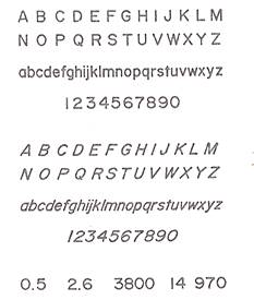
All pencil lettering should be produced freehand and drawn between a pair of faint guide lines. For dimensions and notes a character height of about 3mm should be used, and characters should be about the same height. Titles ar generally made in larger characters. Characters must touch the guidelines and be consistent in width. As an aid to spacing words consistently, imagine an “I” to be placed between them. The space between lines of lettering should not be less than half the character height.
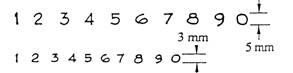
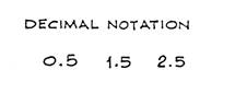
The addition of sizes and measurements to a drawing is known as “dimensioning”. Dimensions tell us the exact distance between two points of surfaces, therefore it is essential that they are legible. Take particular care in writing dimensions and base them on the numerals shown below.
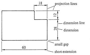
He dimensioning of every object will involve the elements shown in the diagram below. Consider this object to be a piece of sheet metal. Both projection and dimension lines are thin continuous lines.
Depending on the situation, dimension lines can end in any of the following ways:
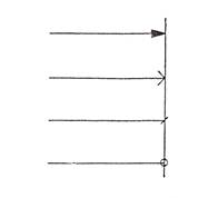
For general use, solid arrowheads are preferred. In general, only one type of “ending” should be used on any drawing.
Dimension line endings
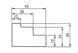
Parallel dimensioning consists of a number of dimensions originating from a datum feature. This type of dimensioning is used where a high standard of accuracy is required.
Superimposed running dimensioning is simplified parallel dimensioning, and may be used where space is limited. The common origin is indicated as shown in the figure above. Dimensions are placed near the arrowhead and clear of the dimension line.
Chains of dimensions are used where the adding together of measurements does not affect the accuracy of the component.
Combined dimensioning uses both chain dimensioning and parallel 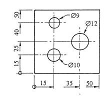
dimensioning.
Dimensioning by coordinates: superimposed running dimensions may be used in two directions at right angles as shown in the figure above. The common origin can be any suitable datum feature.
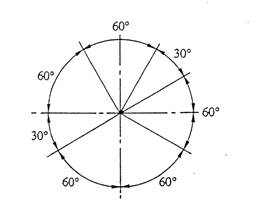
Dimensioning angles: note that all dimensions are outside the arcs and are horizontal.
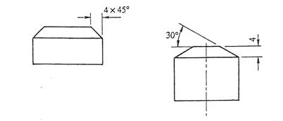
Dimensioning chamfers: It is important to realise that dimensions should not be added to a drawing in a random fashion.
All drawings should be made in full size if possible, but if the size of the object is such as to make this impossible thy must be drawn in proportion, that is, to a uniform scale. The scale used must be stated on the drawing as a ratio or representative fraction, for example scale 1:2 which means half size. It is common for a note to warn against scaling the drawing since prints may stretch or shrink.
Scale multipliers and divisors of 2,5 and 10 are recommended and representative fraction of the most commonly used scales are:
1: 1 Full size
1: 2 Half full size
1 :5 One-fifth full size
1: 10 One-tenth full size
2: 1 Twice full size
5: 1 Five times full size
10: 1 Ten times full size
Orthographic projection uses multiple views of an object, from points of view rotated about the objects centre through increments of 90 degrees. In first angle projection, each view of the object is projected in the direction (sense) of sight of the object. In third angle projection, each view of the object is projected opposite to the direction (sense) of sight of the object.
An engineering drawing is a graphical language or an international language, and is one of the main forms of communication in the workshop or on site. In oral or written communication were the only means of communication when dealing with technical matters, misunderstandings could arise, particularly in relation to shape and size which could have serious implications for a company. An engineering drawing is used to transfer a mental picture of an object from the drawing office to the workshop or site.
A drawing must give sufficient information to enable the craftsperson to convert the information given, into a finished component or job without further contact with the drawing office.
The types of line for engineering drawings recommended in the British Standards Institution in BS 8888: 2004. Two line thicknesses are recommended: thick 0.7mm wide and thin 0.3mm wide.
All drawings should be made in full size if possible, but if the size of the object is such as to make this impossible thy must be drawn in proportion, that is, to a uniform scale. The scale used must be stated on the drawing as a ratio or representative fraction, for example scale 1:2 which means half size. It is common for a note to warn against scaling the drawing since prints may stretch or shrink.
Source: http://local.ecollege.ie/Content/APPRENTICE/liu/ind_insulation/mod2/m2_u2.doc
Web site to visit: http://local.ecollege.ie
Author of the text: indicated on the source document of the above text
If you are the author of the text above and you not agree to share your knowledge for teaching, research, scholarship (for fair use as indicated in the United States copyrigh low) please send us an e-mail and we will remove your text quickly. Fair use is a limitation and exception to the exclusive right granted by copyright law to the author of a creative work. In United States copyright law, fair use is a doctrine that permits limited use of copyrighted material without acquiring permission from the rights holders. Examples of fair use include commentary, search engines, criticism, news reporting, research, teaching, library archiving and scholarship. It provides for the legal, unlicensed citation or incorporation of copyrighted material in another author's work under a four-factor balancing test. (source: http://en.wikipedia.org/wiki/Fair_use)
The information of medicine and health contained in the site are of a general nature and purpose which is purely informative and for this reason may not replace in any case, the council of a doctor or a qualified entity legally to the profession.
The texts are the property of their respective authors and we thank them for giving us the opportunity to share for free to students, teachers and users of the Web their texts will used only for illustrative educational and scientific purposes only.
All the information in our site are given for nonprofit educational purposes