6.1 Flow regimes
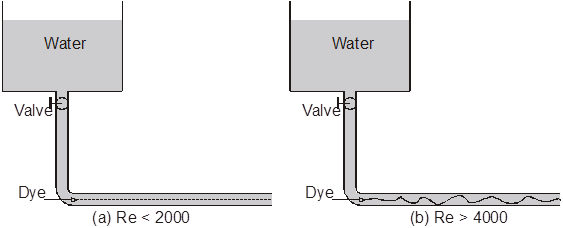
Figure 6.1-1 Reynolds’ experiment.
Laminar or well-ordered type of flow exists when adjacent fluid layers slide smoothly over one another. Mixing between layers occurs only on a molecular level. Turbulent flow exists when packets of fluid particles are transferred between layers, giving the flow a fluctuating nature. Osborn Reynolds first described the existence of laminar and turbulent flow quantitatively through his classic experiment in 1883. As shown in Figure 6.1-1, water was allowed to flow through a transparent pipe at a rate controlled by a valve. Reynolds introduced a dye having the same specific gravity as water into the flow to observe what was happening. He found that at low flow rates the dye pattern was regular and formed a single line of color as show in Figure 6.1-1(a). The pressure drop was also found to directly proportional to the flow rate. As the flow rate was increased a point was reach where the dye trace was seen to be unstable and it broke up after a short distance. At still higher flow rates the dye almost immediately dispersed throughout the pipe cross section. The relationship between pressure drop and flow rate now became almost quadratic instead of linear.
The stable flow observed initially was called laminar flow. The unstable flow pattern, characterized by high degree of mixing between the fluid elements, was called turbulent flow. There is a transition region in between laminar and turbulent where the flow is unstable but not thoroughly mixed. Laminar flow in a tube persists up to a point where the value of the Reynolds number is about 2000. Reynolds number is defined as
NRe = ![]() =
= ![]()
The Reynolds number is a ratio of the inertial momentum flux (rV2) in the flow direction to the viscous shear stress or viscous momentum flux in the transverse (mV/D) direction. Turbulent flow occurs when Reynolds number is greater than about 4000. Viscous forces are a manifestation of intermolecular attractive forces that stabilize the flow. Therefore stable laminar flow should occur at low Reynolds numbers where viscous forces dominate.
6.2 Generalized Mechanical Energy Balance Equation
For laminar flow of a fluid in a cylindrical tube of radius R and length L, the Hagan-Poiseuille equation provides a relationship between volumetric flow rate and pressure drop across the tube as follows.
Q = ![]() tw =
tw = ![]()
![]() =
= ![]()
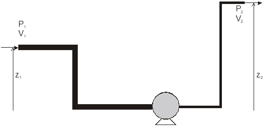
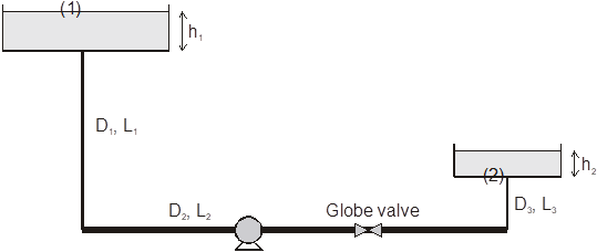
Figure 6.2-1 A general piping system.
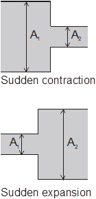
For a general piping system shown in Figure 6.2-1, we need the generalized relationship, equation (6.2-1), that can account for the effect of pressure drop on incompressible fluid flow, changes in elevation, tube cross section, changes in fluid velocity, sudden contractions or expansions, and friction loss through pipe and fittings such as valves and flow meters.
![]() + gz1 +
+ gz1 + ![]() + hwp =
+ hwp = ![]() + gz2 +
+ gz2 + ![]() + ef (6.2-1)
+ ef (6.2-1)
Each term in this equation has units of energy per unit fluid mass flow rate or (length/time)2.
P = pressure
r = fluid density
g = acceleration of gravity
z = elevation relative to a reference surface
V = average fluid velocity
a = kinetic energy correction factor
a = 2 for laminar flow
a = 1 for turbulent flow
wp = work done per unit mass flow rate
h = pump efficiency (h < 1)
ef = friction loss due to piping and fitting
The friction loss is given by the following equation
ef = 4![]()
![]()
![]() +
+ ![]() Kfitting,j (6.2-2)
Kfitting,j (6.2-2)
where
fi = ![]() = friction factor in tube segment i with length Li and diameter Di.
= friction factor in tube segment i with length Li and diameter Di.
Vi = average velocity within tube segment i.
Kfitting = friction loss factor or loss coefficient for pipe fittings, some typical values are given in Table 6.2-1. The velocity Vj in the summation is for the fluid just downstream of the contraction, expansion, or fitting.
Table 6.2-1 Friction loss factor for various pipe fittings.
Fitting |
Kfitting |
|
Globe valve, wide open Sudden expansion |
7.5 |
|
The friction factor for laminar flow (NRe = ![]() < 2000) is given by
< 2000) is given by
f = ![]() (6.2-3)
(6.2-3)
The friction factor for turbulent flow (Re > 4000) can be estimated by
f = {- 1.737 ln[0.269![]() -
- ![]() ln (0.269
ln (0.269![]() +
+ ![]() )]}-2 (6.2-4)
)]}-2 (6.2-4)
In this equation e is the surface pipe roughness and D is the inside pipe diameter. Representative values for surface roughness are given in Table 6.2-2.
Table 6.2-2 Surface roughness
Surface |
e (ft) |
e (mm) |
Concrete |
0.001-0.01 |
0.3-3.0 |
Equation (6.2-5) developed by Churchill1 adequately predicts the Fanning fiction factor over the entire range of Reynolds number including a reasonable estimate for the transition region between laminar and turbulent flow.
f = 2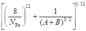 (6.2-5)
In this equation A = 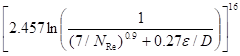 and B =
If the fluid flows through a noncircular duct, then the equivalent diameter, Deq, can be used in equations (6.2-2, 3, 4, 5). The equivalent diameter is defined as
Deq = 4rH = 4![]()
where rH = hydraulic radius
Across = cross sectional area of the flow
Pwet = wetted perimeter of the duct
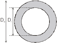
Figure 6.2-2 Flow through an annular tube.
For the flow through an annular tube, the equivalent diameter is given as
Deq = 4![]() = Do - Di
= Do - Di
Example 6.2-1. ----------------------------------------------------------------------------------
Water is pumped from the upper reservoir to the lower reservoir through the piping system shown. Determine the power required for the pump if the water flow rate is 60 kg/s. The fittings from pipe D1 to pipe D2 and from pipe D2 to pipe D3 can be considered to be standard 90o elbows. Data:
h1 = 10 m, h2 = 3 m, L1 = 50 m, L2 = 300 m, L3 = 2 m, D1 = 0.2 m, D2 = 0.5 m, D3 = 0.03 m, water viscosity = 1 cP = 10-3 kg/m×s, r = 1000 kg/m3. The pipe roughness is 0.05 mm. The pump efficiency is 75%.
Solution ------------------------------------------------------------------------------------------
Applying the mechanical energy balance between (1) and (2) we have
![]() + gz1 +
+ gz1 + ![]() + hwp =
+ hwp = ![]() + gz2 +
+ gz2 + ![]() + ef
+ ef
Let the reference level be at (2), the end of pipe 3, the energy equation becomes
![]() + g(h1 + L1 - L3) + 0 + hwp =
+ g(h1 + L1 - L3) + 0 + hwp = ![]() + 0 +
+ 0 + ![]() + ef
+ ef
g(h1 + L1 - L3) + hwp = gh2 +![]() + ef
+ ef
D(m) |
A(m2) |
V(m/s) |
NRe |
e/D |
f |
.2 |
3.14´10-2 |
1.91 |
3.82´105 |
2.50´10-4 |
0.00406 |
ef = 4![]()
![]()
![]() +
+ ![]() Kfitting,j
Kfitting,j
4![]()
![]() = 2´ 10-3[4.06´
= 2´ 10-3[4.06´![]() + 4.31´
+ 4.31´![]() + 6´
+ 6´![]() ]
]
= 5.77´ 103 m2/s2
![]() Kfitting,j = 0.5´1.912´0.4 sudden contraction, Kfitting = 0.4
Kfitting,j = 0.5´1.912´0.4 sudden contraction, Kfitting = 0.4
+ 0.5´0.3062´0.7 standard 90o elbow, Kfitting = 0.7
+ 0.5´0.3062´7.5 open globe valve, Kfitting = 7.5
+ 0.5´84.92´0.7 standard 90o elbow, Kfitting = 0.7
![]() Kfitting,j = 2.52´ 103 m2/s2
Kfitting,j = 2.52´ 103 m2/s2
Therefore ef = 5.77´103 + 2.52´103 = 8.29´103 m2/s2
g(h1 + L1 - L3) + hwp = gh2 +![]() + ef
+ ef
9.81(10 + 50 - 2) + 0.75wp = 9.81´3 + ![]() + 8.29´103
+ 8.29´103
wp = 1.51´104 m2/s2
The power required for the pump is
![]() =
= ![]() wp = 60´1.51´104 = 9.08´105 W = 1220 hp
wp = 60´1.51´104 = 9.08´105 W = 1220 hp
Note: 1 hp = 746 W
1 Churchill SW, Chem. Eng., Nov. 7, 1977, p. 91
Source: https://www.cpp.edu/~tknguyen/che311/notes/Chap6-1.doc
Web site to visit: https://www.cpp.edu/
Author of the text: indicated on the source document of the above text
If you are the author of the text above and you not agree to share your knowledge for teaching, research, scholarship (for fair use as indicated in the United States copyrigh low) please send us an e-mail and we will remove your text quickly. Fair use is a limitation and exception to the exclusive right granted by copyright law to the author of a creative work. In United States copyright law, fair use is a doctrine that permits limited use of copyrighted material without acquiring permission from the rights holders. Examples of fair use include commentary, search engines, criticism, news reporting, research, teaching, library archiving and scholarship. It provides for the legal, unlicensed citation or incorporation of copyrighted material in another author's work under a four-factor balancing test. (source: http://en.wikipedia.org/wiki/Fair_use)
The information of medicine and health contained in the site are of a general nature and purpose which is purely informative and for this reason may not replace in any case, the council of a doctor or a qualified entity legally to the profession.
The texts are the property of their respective authors and we thank them for giving us the opportunity to share for free to students, teachers and users of the Web their texts will used only for illustrative educational and scientific purposes only.
All the information in our site are given for nonprofit educational purposes