
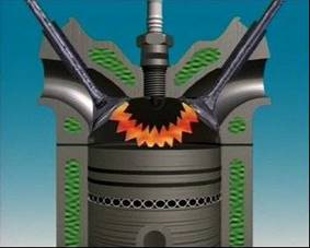
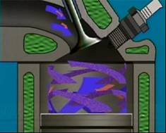
 This is a cylinder for a 4-stroke Diesel engine. The first step is to get the air into the cylinder. Air enters through an inlet port that is opened and closed by an inlet valve. This is called Intake. Next is compression. The piston compresses the air, which in turn heats the air. Fuel is then injected into the cylinder in a very fine spray. The heat from the compressed air ignites the fuel and it burns. This burning is called combustion.
The burning gases expand rapidly, and push the piston down the cylinder until it reaches bottom dead centre. The reciprocating action of the piston turns into the rotary motion of the crankshaft. The crankshaft forces the piston back up the cylinder, pushing leftover gases out past an exhaust valve. And everything is back where it started; ready to repeat the whole process.
The whole process is a cycle. A new charge enters and is ignited. Combustion occurs; expanding gases drive the piston down and turn the crankshaft which pushes the piston back up the cylinder. How they happen can change but they are always there. In one 4-stroke cycle, the crankshaft does 2 revolutions. In those 2 revolutions how many strokes does the piston make? It does 4 strokes. Out of those 4 strokes how many actually produce energy? In one 4-stroke cycle, only 1 stroke out of 4 delivers new energy to turn the crankshaft.
 What is a stroke? It’s the movement of the piston from TDC (top dead centre) to BDC (bottom dead centre), OR BDC to TDC. A 4-stroke engine has the following "strokes", intake, compression, power, and exhaust.
A 4-stroke Diesel Engine uses "internal" combustion, meaning that the heat that causes the air in the cylinder to expand is generated "internally". (A steam engine is actually an "external combustion engine" as its heat source is outside the cylinder!)Those 4 strokes must include - Intake, Compression, IGNITION, Power & Exhaust. Let’s look at a simplified model. Note that the valves are ONLY open during their respective strokes, IE: intake valve open ONLY during the intake stroke, exhaust valve only during the exhaust stroke. Both are CLOSED during compression and power!
The intake stroke starts with the exhaust valve closed, the inlet valve opening, and the piston at its highest point, top dead centre.
It starts to move down, increasing the volume above the top of the piston. This makes pressure inside the cylinder lower than the pressure outside. This higher outside air pressure forces the air into the cylinder. The piston reaches bottom dead centre, the inlet valve closes, and the intake stroke ends.
Both intake and exhaust valves stay closed as the piston leaves bottom dead centre. The piston moves up, squeezing the air into a smaller and smaller volume, which compresses it. That causes the air charge temperature to rise, and that makes ignition easier and combustion (burning of fuel) more complete.
Just before the piston reaches top dead centre, the next key event occurs - Ignition. The air expanding in the cylinder pushes the piston down the cylinder. This is the Power stroke that drives the engine. The piston now moves from bottom dead centre to top dead centre. The exhaust valve opens, and the piston pushes out the leftover gases. Let’s look at a complete 4-stroke cycle:
The way engine cylinders are arranged is called the engine configuration. Tilting an engine reduces its height. This can reduce the height of the bonnet as well, which allows a more streamlined body shape.
Tilting can be carried to an extreme by laying the engine completely on its side. It is then called a flat engine. This greatly reduces engine height.
As the number of cylinders increases, the length of the block and the crankshaft can become a problem. One way to avoid this is with a V configuration. This design makes the engine block and the crankshaft shorter, and more rigid.
In vehicle applications, the number of cylinders can vary, usually from 4, up to 12. Common angles between the banks of cylinders are 90 degrees and 60 degrees.
V-type engines are wider than inline engines, and may also be lower.
Horizontally-opposed engines have 2 banks of cylinders, 180 degrees apart, on opposite sides of the crankshaft. A useful design when little vertical space is available. It is shorter than a comparable in-line engine but wider than a V-type.
Rotary engines use a rotor in housing, instead of a piston in a cylinder. This provides a very compact power unit.
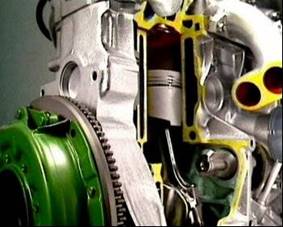
The cylinder block is the largest part of the engine. Its upper section carries the cylinders and pistons. Normally, the lower section forms the crankcase, and supports the crankshaft. It can be cast in one piece from grey iron. Or it can be alloyed with other metals like nickel or chromium.
The iron casting process begins by making up the shapes of what will become water jackets and cylinders as sand cores which are fitted into moulds. This stops these parts becoming solid iron during casting.
Molten iron is poured into sand moulds that are formed by patterns in the shape of the block.
After casting, core sand is removed through holes in the sides and ends, leaving spaces for the cooling and lubricant passages. These holes are sealed with core or welsh plugs. The casting is then machined. Cylinders are bored and finished, surfaces smoothed, holes drilled and threads cut.
All cylinder blocks are made with ribs, webs and fillets to provide rigidity but also keep weight to a minimum.
As more manufacturers try to make vehicles lighter and more fuel efficient, more and more engine blocks are being cast from aluminum.
A block made of aluminum alloy is lighter than if it were made of cast iron. So if two engines are generating the same power, the alloy version would have a better weight-to-power ratio than the cast iron version.
Aluminum alloy blocks are made by various casting processes, including pressure casting. Another method is gravity casting, where the molten metal is poured into molds.
Cast iron liners are usually used in the cylinders of aluminum blocks, and sometimes in cast-iron blocks. Some sleeves are cast into the block.. Grooves on the outside form a key that stops any movement in the cylinder. They also increase surface area to assist heat transfer from the sleeve to the block.
Some blocks don’t need liners. They can be made of wear resistant material that makes a hard-wearing surface for the pistons and piston rings. Or the cylinder bore may have some sort of surface treatment to make it hard-wearing.
When the cylinders, block and crankcase are all cast together, it is called a mono-block construction. A horizontally-opposed block has a split crankcase. The two engine blocks are joined together by the flanges of the crankcase.
In air-cooled engines, the cylinders are usually made as separate parts, and then bolted to the same crankcase. Each cylinder has cooling fins. They’re often machined to give uniform thickness and allow free flow of air.
The power developed by an engine can be increased by:
A single large cylinder would seem the most popular choice since there are fewer parts to manufacture and maintain, but the disadvantages far outweighs the advantages. A large single cylinder engine needs a heavy flywheel to carry the piston over its idle strokes and to smooth out the torque fluctuations. Due to the fact that there is only one power stroke per two revolutions of the crankshaft, the piston and con-rod would also be heavier which means the engine speed would be limited and acceleration slow. As a result the power output-weight ratio would be low.
A multi-cylinder engine of the same cubic capacity and weight would have more power strokes per revolution. Lighter pistons, con-rods and flywheel which means that the torque would be smoother, better balance engine, higher engine speed and more power output.
Commercial vehicle engines are usually four/six or eight cylinder four stroke engines arranged inline depending on the required pulling power. Other variations are the `V-type` configuration .
Cylinder sleeves are used in engine blocks to provide a hard-wearing material for pistons and piston rings. The block can be made of one kind of iron that’s light and easy to cast, while the sleeve uses another kind that is better able to stand up to wear and tear.
There are three main types of sleeves - dry, flanged dry, and wet.
The dry sleeve can be cast in or pressed into a new block, or used to recondition badly-worn or damaged cylinders that can’t easily be re-bored. It’s a pressed fit in its bore in the cylinder blocks. Its wall is about 2mm thick. Its outer surface is in contact with the block for its full length. Its top finishes flush with the top of the block and can hardly be seen. Once in place, dry sleeves become a permanent part of the cylinder block.
A flanged, dry sleeve is like a normal dry sleeve, but a flange at the top fits into a recess in the surface of the engine block. It’s not a tight fit and it can be replaced if it’s worn.
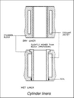 With a wet sleeve, the outer surface is part of the water-jacket around the cylinder. It’s called wet because it has coolant against its outer surface. This helps speed up heat transfer between the sleeve and coolant. The sleeve is sealed at the top to prevent coolant leaks. This stops coolant entering the combustion chamber, and the bottom of the crankcase. A flange at the top of the sleeve fits into a recess in the block. The lower end has 1 or 2 neoprene sealing rings.
The walls on wet sleeves are thicker than on dry sleeves. They don’t have the same support from the block as dry sleeves so they depend on their wall thickness to stop distortion.
In diesel engines, vibration caused by combustion can cause cavitation. This damage appears similar to corrosion and it can eventually destroy the cylinder.
Grey iron is a form of cast iron. There are many different kinds of cast iron, depending on the particular materials they contain.
Grey iron is a cast iron that contains carbon in the form of graphite, plus silicon, manganese and phosphorus. The fractured surface of a cast iron with graphite appears grey, hence the name. It is brittle and cannot absorb shocks. It resists heat and corrosion, and can be cast into many different shapes. It is used for many components.
The cylinder head bolts onto the top of the cylinder block where it forms the top of the combustion chamber.
In-line engines of light vehicles have just one cylinder head for all the cylinders. Larger in-line engines can have 2 or more.
V-type and horizontally-opposed engines have a separate cylinder head for each bank of cylinders.
Just as with engine blocks, cylinder heads can be made of cast iron, or aluminum alloy. A head made of aluminum alloy is lighter than if it were made of cast iron. Aluminum also conducts heat away more quickly than iron. So with an aluminum-alloy head, the heat of combustion can be conducted away into the coolant more quickly.
Manufacturing the head is similar to manufacturing the block. A casting mold is made. Sand cores are put in to form any hollow areas. Depending on the engine, these can be for coolant and lubricant passages, and inlet and exhaust ports.
Air-cooled engines have cooling fins cast into the cylinder head. The underside of the head is shaped to form the combustion chamber.
4.2 Cylinder head design
 Cylinder heads are designed to help improve the swirl or turbulence of the air-fuel mixture, and prevent fuel droplets settling on the surfaces of the combustion chamber or cylinder walls.
When air-fuel mixture is compressed between the piston and the flat part of the cylinder head, it produces what’s called “squish”. That means squeezing of the gases to increase their velocity and turbulence.
In gasoline engines, the three most popular combustion chamber designs are called hemispherical pent roof, bath-tub and wedge.
A hemispherical, or pent-roof combustion chamber has the intake valve on one side of the chamber and the exhaust valve on the other. This provides crossflow. Air-fuel mixture enters on one side, and exhaust gases exit on the other. Positioning the valves in this way leaves room for relatively large valves and ports, and that helps the engine breathe. Breathing refers to the engine taking in the air or air-fuel mixture. Fuel starts to burn at the plug, then burning travels outward in all directions. This is called flame propagation. With the plug in the middle of the hemisphere, the flame front has less distance to travel than in some other designs, which gives rapid and effective combustion. This design is common in a lot of passenger vehicles.
The bath-tub combustion chamber is oval-shaped, like an inverted bathtub. Valves are mounted vertically and side by side, making them simple to operate. The plug is to one side, and that creates a short flame path. It all helps increase turbulence.
The wedge-shaped combustion chamber tapers away from the plug which is at the thick end of the wedge. The valves are in line and inclined from the vertical. This design usually has a smaller surface area than the others, with less area where fuel droplets can condense. Less fuel is left unburned after combustion, which reduces hydrocarbon exhaust emissions. And since the flame is directed toward the small end of the wedge, damage caused by detonation is reduced.
4.3 Intake and exhaust passages
The size of passages in the head can affect engine output. Smaller intake and exhaust passages and ports allow more torque at low engine and give more efficient combustion.
At high speeds however, these smaller passages restrict airflow. To reduce the effect of this, the diagram shows an engine with two inlet valves. One opens at low speed and the other operates at higher engine speeds. Larger passages produce greater power at high engine speeds.
Each intake and exhaust passage can be formed separately in the head. Intake passages for adjacent passages may have a common, thin wall between them. This is called siamesed. Exhaust ports in the same head can also be siamesed.
When all intake and exhaust ports are on one side, it is called a counter-flow head. They can be cast separately or siamesed.
When all of the intake ports are on one side and exhaust ports are on the other, it is called a cross-flow head. This allows for straighter passageways and higher efficiency.
Gaskets form a seal by being compressed between stationary parts where liquid or gas could pass. Most gaskets are made to be used only once. They can be made of soft materials such as cork, rubber, nitrile, paper, heat resistant materials or graphite; or they can also be made of soft alloys and metals such as brass, copper, aluminum or soft steel sheet metal. Such materials may be used individually or in some cases as blends to produce the required functional material.
With the advent of environmental factors and a reduction in the use of asbestos, replacement materials have been developed. Some of these modern special materials that are now used for the side layers of head gaskets are designed to withstand temperatures up to 2100 degrees `F `or 1150 degrees `C`. Such materials are also designed to allow the cylinder head and block, some of which have considerable distortion rates, to move slightly on the head gasket as they expand during engine warm-up. This feature is vital for preventing head gasket failure.
Some head gaskets also incorporate stainless steel fire rings to help to contain heat and pressure within the cylinder. In addition, many head gaskets also have an added silicone based outer coating on both sides of the side material layers to provide additional cold sealing ability during start-up and warm-up. Head gaskets also seal oil passages, and control the flow of coolant between the cylinder block and head and are fitted with beads or rings to prevent leakage and corrosion.
Some joints between surfaces on modern engines are being sealed with special sealants which eliminate the use of gaskets in some applications. Pure rubber, or conventional cork-rubber is unable to deal with the stresses and pressures in modern engines.
Gaskets around a rotating part would quickly wear out and leak. To seal these parts, oil seals are needed. The most widely used is the lip type dynamic oil seal. It has a shaped dynamic rubber lip that’s held in contact with the shaft to be sealed by a circular coil spring called a garter spring.
A similar sealing principle is used to seal the valve stem to prevent oil entering the engine combustion chamber. Rotating or sliding shafts can also be sealed by using “O” rings, but generally they are not as durable in most applications as the lip-type seal.
Various materials are used in modern oil seals, some being impregnated with special coating materials that are designed to increase their sealing ability on worn shafts. As a general rule, oil seals must be replaced when a component is overhauled.
Head gaskets seal and contain the pressures of combustion within the engine, between the cylinder head and the block. Some high temperature head gaskets are called 'anisotropic' in nature. This means that the gasket is designed to conduct heat laterally to transfer heat from the engine to the coolant faster. They are normally constructed with a steel core. Special facing materials are added to both sides of the gasket core to provide a comprehensive seal under varying torque conditions.
Gasket manufacturers have produced improved material combinations such as nitrile and cork blends because pure rubber, or conventional cork-rubber, is unable to deal with the stresses and pressures of 'high tech' engines. Such combinations are more able to deal with issues such as compressibility and wicking.
Some materials are designed to 'swell' in application and increase sealing ability. For instance when oil inside a valve cover penetrates the edge of the gasket material, it is designed to swell by approximately 30%. This swelling effect increases the sealing pressure between the head and valve cover sealing surfaces and helps to seal potential leaks.
4.6 Turbulence
 Turbulence refers to the swirling motion of a liquid or a gas.
It helps to maximize the mixing of air and fuel, which helps make sure the combustion process occurs efficiently. Without turbulence, the air-fuel mixture can form local areas of high pressure and temperature that can cause detonation during combustion. A high level of turbulence can prevent this .This will be covered in greater detail in the Diesel Fuel module.
Petrol engines must control the flow of combustible mixture they take in, and when it goes in.
Diesel engines are different. Their power and speeds are controlled by the amount of fuel injected, so it isn’t necessary to control airflow into the intake manifold.
Almost all 4-stroke gasoline and diesel engines use valves, which are located in the cylinder head.
Valves experience enormous stress even in normal conditions. In a 4-cylinder car driven at around 90 kph, each valve opens and closes about 30 times a second. Exhaust valves withstand huge temperatures and they can become red-hot.
A valve must not soften at high temperatures. It needs good hot strength to stand up to being forced against the seat, and to prevent tensile failure in the stem. It needs good fatigue properties to overcome cracking. Various surface treatments are used to help the valve resist wear, burning and corrosion.
Inlet valves are made of steels mixed with chromium or silicon to make them more resistant to corrosion, and manganese and nickel to improve their strength. Exhaust valves are made of nickel-based alloys. Some high performance applications use especially hard-wearing titanium alloys.
A poppet or mushroom valve has 2 main parts, a stem and a head. It fits into a port in the head. Its face makes a gas-tight seal against the seat.
During operation, the head near the face of the valve transfers heat to the seat. Some is conducted up into the valve stem. The stem transfers heat on to the guide, so the stem is the valve’s coolest part.
The valve seat and guide are also cooled by coolant in passages around the valve ports.
When a valve does not seat properly, there’s a smaller area where heat transfer can occur. That means the face will overheat. Local hot spots can reach such extreme temperatures that the edge of the valve can actually burn. The width of the valve seat is important. A narrow seat is desirable because a thin circular contact with the valve face forms an efficient seal.
But a wider seat is better for transferring heat from the valve to the cylinder head. A common compromise is for the inlet valve to have a narrower seat than the exhaust valve
In some cast-iron cylinder heads, the seats are cut directly into the edge of the valve port. These valve seat areas are machined from the metal of the cylinder head. In some engines, the valve seat area is hardened during manufacture.
In others, hard metal valve seat inserts are pressed into the machined holes. Valve seat inserts are metal rings that match the shape of the valve. They are usually made of an iron alloy. They are used in aluminum cylinder heads to provide a sealing surface for seating the valve.
The faces of the valve are ground at an angle of 45 degrees or 30 degrees. Some engines use 30 degrees or 45 degrees face angles for inlet valves, and 45 degrees for exhaust valves.
Valve seats are often ground to the same angle as the valve face, but they can differ. The difference is called an interference angle. An interference angle allows for a quick bedding-in of the valve face to the seat on new engines. It may also allow for slight changes in angle as a valve heats and expands.
As the valve opens and closes, it has a natural tendency to rotate, very gradually, so that it keeps seating in a new place. This produces a slight wiping action which helps keep the face and seat free of carbon. It also helps prevent sticking in the valve guide and distributes heat around the valve seat.
On some diesels, the inlet valve has a shroud or mask on the back of the valve head. This is designed to cause turbulence in the incoming air. The position of this mask is critical for best operation, so the valve is pinned to prevent it rotating. If the rocker arm is slightly offset to the valve stem, it can help this rotation.
Some engines even use positive valve rotators. The valve operates in a valve guide and it is exactly concentric with the valve seat. The valve guide is the hollow cylindrical part in which the valve stem moves.
The valve guide area can be machined from the metal of the cylinder head, or holes can be drilled for pressed-in guides. Cast-iron guides are necessary in aluminium-alloy heads to provide a suitable bearing surface for the valve stem.
Many heads use replaceable valve guides that are a form of metal bush pressed into holes in the cylinder head. Other cylinder heads have guides cast as part of the cylinder head, then bored to the size of the valve stem during manufacture.
Oil seals are fitted to the valve stems or the guides on both intake and exhaust valves. They prevent too much oil passing down into the combustion chamber.
The coil spring on the outside holds the sealing edge against the valve stem. The angle at the top of the seal forms a small reservoir of oil to lubricate the stem and guide. If there is too much oil there, carbon deposits form in the port and on the valve head.
Umbrella seals shed the oil and keep it away from the end of the valve guide. Worn seals or guides or too much valve-guide clearance will let oil pass the intake valve.
The inlet valve is more likely to pass oil through its guide than the exhaust valve. This is because of the low pressure in the inlet port that draws in the oil.
The exhaust valve can still have problems because of exhaust pulsing. This creates a low pressure area behind the gases, which can cause oil to pass down the valve guide.
Valves are normally held on their seats by 1 or 2 coil springs that are compressed between the cylinder head and a retainer on the valve stem.
The spring retainer is held on the end of the valve stem by conical shaped collets. Collets are also known as cotters, keepers or keys. The springs usually have their coils closer at the bottom than the top. This makes different parts of the spring vibrate at different frequencies, and prevents wasteful valve spring vibration. They can also be made of wire with an especially shaped strong section that limits valve bounce.
Intake valves pass only air so they run at much lower temperatures than exhaust valves.
They are usually larger than exhaust valves because the pressure forcing the charge into the cylinder is much lower than the pressure forcing the exhaust gases out of the cylinder. Exhaust gases under pressure need much less space.
Different engines use different valve combinations.
Having more than 1 inlet valve provides better breathing. An additional inlet valve allows larger inlet passages and a freer flow into the cylinder, so the engine receives a better charge.
Similarly, two exhaust valves mean the cylinder can be designed with larger exhaust ports, which provides a freer flow of exhaust gases out of the cylinder.
The valve train includes all of the components that are driven from the camshaft to the top of the valves. There are different types of valve trains, depending on how many camshafts there are, and where they are located.
In an overhead valve or pushrod system the valves are in the cylinder head, but the camshaft is in the block near the crankshaft. A valve lifter or tappet rides on the cam. As the cam lobe reaches the lifter, it rises, transfers the motion to the pushrod. This then moves a rocker which in turn pushes the valve open.
There are different kinds of lifters. A solid lifter is usually a hollow, cast iron cylinder mounted in a bore in the crankcase. It is free to rotate slowly, which distributes wear from the cam over the face of the lifter.
The gap between the valve tip and the valve train is called valve clearance or valve lash. This must be maintained when the cam is not applying pressure to open the valve. It can be adjusted with a screw and locknut built into the rocker arm. These adjustments are needed regularly.
Many engines now use hydraulic valve lifters. Their purpose is to make the engine quieter and eliminate the need for valve clearance adjustment. When the engine is operating, oil under pressure from the engine’s lubrication system is supplied to the lifter.
The oil is assisted by spring tension to maintain zero valve clearance but through a system of valves it is trapped in the lifter as the camshaft lifts it. Since oil is not compressible, the lifter acts like a solid lifter. When the valve is closed, any oil lost during the previous lift is replaced, and zero valve clearance is maintained.
Rocker arms transfer motion to the valves. The rocker arm rocks up and down using a pivot mechanism. Some rocker arms are made of cast steel or aluminum alloy. Others are a steel pressing. Hydraulic valve lifters usually use stamped, or pressed, sheet metal or cast aluminum rocker arms.
To see how valve-timing works in a 4-stroke engine cycle, let’s show piston motion as a circle. In this simple cycle, each stroke is shown as a semi-circle.
This intake valve opens at top dead centre, and closes at bottom dead centre. The blue line shows that period and it matches the intake stroke.
The exhaust valve opens at bottom dead centre, and then closes at top dead centre before the new air-charge enters the cylinder.
In practice, the intake valve usually opens earlier than top dead centre, and stays open a little past bottom dead centre. The exhaust valve opens a little before bottom dead centre, and stays open a little past top dead centre.
When the valves actually open and close, can be measured by angles. To make these angles easier to read, let’s use a spiral instead of a circle.
This intake valve opens 12° before the piston reaches top dead centre. And it closes 40° after bottom dead centre. The exhaust valve opens 47° before bottom dead centre - and stays open - until 21° past top dead centre. This gives exhaust gases more time to leave.
By the time the piston is at 47° before bottom dead centre on the power stroke, combustion pressures have dropped considerably and little power is lost by letting the exhaust gases have more time to exit.
When an intake valve opens before top dead centre and the exhaust valve opens before bottom dead centre, it is called lead. When an intake valve closes after bottom dead centre, and the exhaust valve closes after top dead centre, it is called lag.
On the exhaust stroke, the intake and exhaust valve are open at the same time for a few degrees around top dead centre. This is called valve overlap. On this engine, it is 33°. Different engines use different timings. Manufacturer specifications contain the exact information.
Valve overlap is the amount of time the intake and exhaust valves are both open at once. Less overlap produces a smooth idle and slower speed torque, but poor high speed performance because there is not enough time for complete scavenging to occur. More valve overlap allows better engine breathing at high speeds, but poor performance at low speeds, rough idling, and higher exhaust emissions.
Engines with fixed valve timing can only operate most efficiently at one specific speed. Engines that can vary valve timing and/or valve lift can operate efficiently at a wider range of speeds, and deliver better performance at high speeds, with a flatter torque curve.
There are two types of variable valve timing, or VVT – cam phasing and cam changing.
Cam phasing VVT varies valve timing by shifting the phase angle of the camshaft. At high engine speeds, the inlet camshaft phasing can be rotated in advance to enable earlier intake, increasing the amount of valve overlap. This is controlled by the engine management system, and actuated by hydraulic valve gears.
Phasing change is either continuous or fixed. Continuous systems normally vary the phasing angle between 0 and 40 or more degrees according to engine load and speed requirements. Fixed phasing systems alter phasing by a specific angular value at a specific speed and load condition. Single overhead camshaft engines can use cam phasing. However, double overhead camshaft engines can receive greater benefit from phasing change VVT as the intake and exhaust camshaft can be controlled separately.
Cam changing VVT uses different cam profiles to lift the valves depending on engine load and speed.
One common system uses two rocker arms for normal operation on its two intake valves, with a third, higher profile, rocker arm between the other two arms. At engine speeds above 5000 to 6000 rpm, the engine ECU activates an oil pressure controlled pin that locks the three rocker arms together. The centre rocker arm follows a larger and more aggressive profile, transferring its movement to the intake valves which now open further and for longer.
When engine speeds fall below the threshold speed, oil pressure is removed from the pin and a spring deactivates the pin. The rocker arms are no longer locked together and the valves are controlled by the less aggressive outer lobes.
Cam changing VVT can also be used in a similar way to deactivate a second intake valve at low engine speeds, increasing the velocity and swirl of the air/fuel mixture as it enters the combustion chamber.
The position of the camshaft depends on the design of the engine. It can be in the engine block close to the crankshaft - this is a called a pushrod or overhead valve system. Or there can be one or two camshafts mounted in the cylinder head.
But in both designs it does much the same job - driving the valves and the distributor, and sometimes the fuel pump, and the oil pump.
The camshaft is made of hardenable iron alloy or steel, and it can be cast or machined. The cam lobes are ground to the proper shape and position in relation to one another.
The camshaft has a cam for each valve. In some cases, there is an additional cam known as an eccentric, to operate the fuel pump. A gear on the camshaft drives the ignition distributor, and, often, an oil pump.
Cylinder 1. |
P |
E |
I |
C |
Cylinder 2. |
E |
I |
C |
P |
Cylinder 3. |
C |
P |
E |
I |
Cylinder 4. |
I |
C |
P |
E |
Degrees of Crankshaft Rotation
Firing Order 1342
Single cylinder Power Stroke Every
![]()
Twin cylinder (Side by Side)
![]()
3 cylinder Inline
![]()
4 cylinder inline
![]()
When a piston is forced down the cylinder during the power stroke it applies the force to the connecting rod. The connecting rod then causes the crankshaft to turn. The force that makes the crankshaft turn is called torque. The metric unit for the measurement of torque is newton meters, the imperial measurement is pounds feet.
If we assume that a shaft has a lever attached perpendicular to its axis, and that lever is 1 meter long. If a force of 100 newton were applied to the end of the lever, the torque applied to the shaft is 100 newton per meter or 100 newton meters. Similarly if a force of 100 pounds were applied to the end of the lever that was 1 foot long, the torque applied to the shaft is 100 pounds per foot or 100 pounds feet.
Power is a term used to describe how much work is done in a period of time. An engine produces POWER by applying TORQUE to a ROTATING shaft. So the measurement of engine power is calculated from the amount of torque applied to the crankshaft and the speed at which it is turning. When expressing engine power it is necessary to express not only the power value, but to include the engine speed at which it occurs.
The metric measurement of power is the Kilowatt.
The watt is the metric system measurement of power, however engine power is expressed in kilowatts, as the watt has such a small value. A kilowatt is equivalent to 1000 newton per meter per second.
There are different standards of power measurement. These are ECE, SAE and DIN
The ECE standard is European. Engine power is measured at 99 kPa of dry air and 25°C (77 F). Friction torque is not taken into consideration at all.
The SAE standard American. Engine power is measured at 99 kPa of dry air and 25°C (77 F) and applies a friction correction and uses a default Mechanical Efficiency (ME) value of 85%. This is approximately correct at peak torque but not at other engine operating speeds.
The DIN standard is determined by the German automotive industry. engine power is calculated at 101.3 kPa of dry air and 20°C (68 F). With the advent of ECE standards, the DIN is rarely used.
5.12 Overhead camshaft
In modern engines, the pushrod system is being replaced by the simpler overhead camshaft arrangement.
The overhead camshaft is located in the cylinder head. There can be 1 or 2 camshafts. Let’s look at a single overhead camshaft arrangement.
Single overhead camshafts can use rocker arms. The cam can lift one end of the rocker arm, or it can press down on the rocker arm.
On double overhead camshaft systems, the most common arrangement is to use a bucket tappet or lifter. It operates in a guide that protects the valve against side thrusts which it would receive if the cam operated directly against the valve.
The adjustment of valve clearance is usually done by changing accurately machined spacers. Spacers are available in a range of thicknesses, and they’re exchanged to obtain the correct clearance. Some overhead cam engines use a hydraulic lash adjuster to reduce lash in the valve train. They have zero clearance at the valve stem so there’s no need for tappet adjustment.
It can be put in the valve end of the rocker arm. Like the hydraulic valve lifter, it has a body with plunger held against the valve stem by a spring. Oil supplied to the adjuster keeps the plunger in contact with the valve and eliminates lash. Lash adjusters can be put in the cylinder head at the end of the rocker arm. The lash adjusters are stationary and have a pivot for the end of the rocker arm. The plunger in the adjuster holds the rocker up against the cam.
In the lash adjuster inside the bucket tappet, the plunger’s hydraulic action holds the bucket body against the cam on the camshaft and also against the tip of the valve stem so that there is zero clearance.
The cam lobe performs 3 jobs. It opens a valve at the proper time and gives it proper lift. It lets it stay open for a sufficient time. Then it lets it close at the proper time. Accurate valve timing is crucial.
Valve timing can vary from engine to engine, as set out in manufacturers’ specifications, in the valve timing diagram.
The shape of the cam is called the cam profile or contour. With the valve lifter resting on the base circle, shown as A, the valve is fully closed and there is clearance between the rocker arm and the valve stem. The cam rotates. The nose of the cam, B, reaches the valve lifter - and the valve is fully open. The closing flank , C, closes the valve gradually so that it doesn’t pound against its seat.
On engines without valve lash adjusters, a quietening ramp is built into the shape of the cam. This makes for quieter operation during the opening of the valve. The shape of the nose determines how long it stays open. The camshaft must always be synchronised to run in time with the crankshaft. This can be done by gears, chains, or toothed, timing belts.
Timing belts and chains are used on overhead camshaft engines, because the camshaft is further from the crankshaft.
This is a typical chain drive system. It uses a hydraulic tensioner which is fed by oil under pressure from the lubrication system. The chain also uses guides to reduce noise and vibration.
The toothed timing belt is made of fibreglass or wire- reinforced synthetic rubber. Its teeth match those on the crankshaft and camshaft pulleys.
Timing belts are quieter than chains but usually require regular manual tensioning. They also have a shorter life than chains. If a belt breaks, it is not only inconvenient but on some engines it can cause a lot of damage.
The toothed, or synchronous timing belt is used for driving camshafts, balance shafts, water pumps and diesel injection pumps.
It has an inner woven core made from fiberglass, Kevlar, or steel braid, coated with synthetic rubber or neoprene. The teeth, which may be square or curved, are molded to close tolerances to match the drive teeth on the crankshaft and timing gears. A molded plastic cover protects the belt from oil or water contamination.
Timing belts have a high working efficiency due to the low friction properties of their construction. This means they require no lubrication and are silent in operation.
Although it stretches little in use, the tension of the timing belt is important. This is normally set with an adjustable idler pulley that applies tension via a spring. This pulley is fixed to the engine by a fastener. Adjustment is performed manually after the timing belt is installed.
Some manufacturers use a spring and oil damper as an automatic belt tensioner. This type of tensioner is effective at reducing timing belt chatter noise as the belt is always under pressure, even as it stretches. A heavy spring acts against a piston attached to a tensioner pushrod. This is mounted so that the tension pulley can apply pressure perpendicular to the back face of the belt. The cylinder is filled with silicone oil, and ball valves allow the piston to be forced out by the spring but prevent the piston from moving rapidly inwards. In operation the spring provides the force that keeps the timing belt tensioned, and the piston valves prevent loss of tension.
When the camshaft is fitted close to the crankshaft then a gear layout similar to Fig. 3a (overleaf) can be used. Spur gears are noisy so helical teeth are generally used. Sometimes the large camshaft gearwheel is made of plastics material and in cases where the distance is large an idler gear is fitted.
Overhead camshafts are often driven by a rubber belt. The belt is notched to form teeth to maintain the correct valve timing. This type of drive is a cheap, quiet and efficient way of driving a camshaft that is mounted far away from the crankshaft. Also this method enables the drive to be easily disconnected when the cylinder head has to be removed. Breakage of the belt can cause a problem especially if the piston strikes an open valve, but reinforced belt materials make belt breakage a rare occurrence.
Camshaft drives
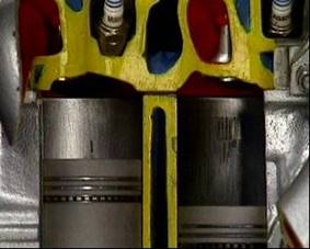
The piston, with its connecting rod and bearing, transfers the force of the combustion and expansion of the power stroke to the crankshaft.
The piston itself, its rings, and the piston or gudgeon pin are together called the piston assembly.
The shape of the piston crown depends on the shape of its combustion chamber, and its compression ratio. In diesel engines, the combustion chamber may be formed totally or in part in the piston crown, depending on the method of injection, so they use pistons with different shapes
The piston crown may be flat, concave, dome, or recessed. The piston must stand up to great heat and pressure. It also must change direction from about 10 times a second to up to hundreds of times a second.
To allow for this, many pistons are machined into a slightly oval shape. This is called cam grinding. Then, as the piston heats up and expands, it becomes round.
Other methods to control expansion include steel struts or ribs, expansion slots in the skirt, or slots called heat dams that restrict movement of the heat.
Piston rings keep a tight seal within the cylinder to stop the heat and pressure in there from escaping.
They also stop oil passing up into the combustion chamber.
New rings and cylinders have minor irregularities and when these wear off, the rings will make a better fit.
To help this along, the rings can be given a porous coating. It’s softer and wears more quickly than the ring material which is usually cast iron.
To prevent wear, the face of the piston ring can be coated with a harder material like chromium that operates well against cast iron without scuffing.
They are split so they can be fitted into grooves in the piston, and to expand against the cylinder walls. When they’re removed, their diameter’s larger than the piston’s. So when they’re installed they’re compressed and the gap is almost closed. Tension in the rings keeps them against the walls.
There are 2 main types of piston rings - compression rings and oil rings.
Compression rings must seal against compression loss during the compression stroke, or the air won’t be fully compressed.
They must also seal properly during the power stroke, or combustion gases are forced past the piston into the crankcase. This is called blow-by.
A plain compression ring has a rectangular section. It is held against the walls by combustion pressure behind the rings.
A tapered ring seals against pressure too but its slightly tapered face helps scrape oil off the walls as well.
A ring that is chamfered or grooved exerts increased pressure against the walls. It is also called a torsion ring. Its shape creates internal forces in the ring so that when it is installed, it twists slightly upwards. During intake, the ring scrapes surplus oil off the walls. During compression, they tend to slide over the oil and not carry it into the combustion chamber. In the power stroke, combustion pressure forces down on the top of the ring and also against its back. This straightens it so that it has full-face contact with the cylinder walls for effective sealing.
Oil-control rings prevent excessive oil working up into the combustion chambers. It can be a one-piece ring that depends on its own tension to hold it against the cylinder walls. Slots in the ring and holes in the piston behind the ring let oil return to the sump.
Many oil-rings are segmental types with 3 or 4 segments. It has 2 side rails and an expander, which also acts as a spacer for the rails. They depend on the expander to hold them against the walls. The expander is made of thin steel with a series of crimps to give it an outward spring force.
The connecting rod connects the piston to the crankshaft. It is fastened to the piston at its little end, by a piston pin, also known as a gudgeon pin.
In some engines the pin is a press fit in the small end of the connecting rod. In others, it is clamped to the connecting rod with a clamping bolt.
Another method lets the pin float in both the piston and connecting rod, and it is held with circlips. There is a brass bushing in the small end of the connecting rod.
The big end of the connecting rod has a detachable cap, and carries 2 halves of the big end bearing. The big end is attached to the crankshaft at the crankpin journal. Connecting rods must be very strong and rigid, and as light as possible. They are subject to stretching, compressing and bending, so they are highly stressed.
They are cast or forged to form an H near the small end and an I near the big end. This shape provides greater strength to resist the stresses than a solid rod of the same mass, it resembles an RSJ or Guilder steel beam used in building construction. To maintain engine balance, all the connecting rods in an engine are a matched set.
An engine’s compression ratio can be a guide to the power it can generate.
It’s not always obvious whether one engine is bigger than another. The size of the engine block can be misleading. Two blocks can be the same size but one has cylinders bored out to larger volumes.
The standard measure of size is called displacement. Displacement is the volume a piston displaces in the cylinder as it moves from its lowest point, or bottom dead centre, to its highest point, top dead centre. This is also called swept volume. Notice that displacement does NOT include the volume above top dead centre.
Engine size is then the sum of the displacements of all of the cylinders of the engine. It is called total engine displacement. For this engine it is 2 liters or approximately 120 cubic inches.
Another guide to engine power is Compression ratio. It compares two volumes in the cylinder. One is swept volume plus clearance volume. That’s the volume above top dead centre. The other is the clearance volume only. Putting these volumes into a ratio gives us the compression ratio - 6 to 1. The larger the first volume, and the smaller the second, the higher the engine’s compression ratio and the more powerful the engine.
The compression ratio shows how much the air taken in during the intake stroke is compressed in the cylinder during the compression stroke. In other words, it is the ratio of the cylinder and combustion chamber volume with the piston at BDC to the combustion chamber volume with the piston at TDC.
This value is calculated as follows:
![]()

Example:

As seen from the two and four stroke cycle. It is very important that the petrol/ air mixture is compressed to the correct pressure during the compression stroke for maximum engine performance.
Loss of compression pressure may be due to a number of faults, but the two most common are worn piston rings, and worn valves.
The object of the compression test is to determine the condition of both piston rings and valves without dismantling the engine.
Compression test: The following is a guide to performing the compression test.
Wet compression test: The procedure for this test is the same as the first test described above but for the following — before the readings are taken a few squirts (5) of oil from an oil can are squirted into the cylinder being tested. This has the effect of sealing the piston to the cylinder whilst the test is being carried out.
The result of the wet test would be either:
Note If the compression test indicates that the valves are the cause of the loss of compression. Before removing cylinder head etc. check valve clearance against manufacturers specification as insufficient valve clearance would cause loss of compression due to the valves not seating correctly.
7. Crankshaft and Assembly
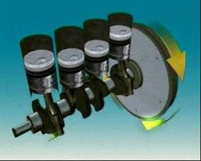 The crankshaft is attached to the connecting rod in offset areas called throws - where the downward power pulses change into rotating motion.
Crankshafts must be strong enough to do this without bending or twisting. They are a one piece casting, or forging, of heat-treated alloy steel of great mechanical strength. Counterweights are formed to balance the throws, and also the big end of the connecting rod.
Fine balancing is done by drilling out or adding small weights. The crankshaft rotates in the engine on journals which run in bearings called the main bearings.
The rear of the crankshaft is drilled and tapped for flywheel attachment. Near the front of the crankshaft, a timing gear or sprocket is attached to drive the camshafts.
Many in-line and `V` engines have a harmonic balancer attached to the crankshaft. The harmonic balancer is more correctly called the crankshaft tortional vibration damper. It prevents crankshaft vibration. In most cases the harmonic balancer incorporates the drive pulley.
No engine can run without bearings. Bearings are used in engines to support and protect rotating parts and allow them to turn freely. The connecting rod must be able to spin freely on the crankshaft. The crankshaft must be able to spin freely in the engine block.
Connecting rod bearings and the crankshaft main bearings are called plain bearings and usually come in two halves, called inserts, slippers or shells.
These precision-inserts have a steel back with a very thin layer of bearing material bonded to it. The bearing material is an alloy that can include metals such as tin, lead, aluminium and copper.
Bearings designed for light duty may be made of white metal. It’s an alloy of tin and lead, with small amounts of copper and antimony.
Alloys of tin and aluminium improve the load-carrying capacity for intermediate applications.
Copper-lead alloys give even more improvements. They’re used in applications such as diesel engines, and high-performance vehicles.
Bearings need a difficult mix of properties. They must be hard enough to resist wear, but soft enough not to damage the shaft.
The soft bearing surface also allows any hard abrasive particles to become embedded in the surface. They can become so deeply embedded; they are prevented from touching the rotating shaft by the film of oil. Plain bearings are classified as friction bearings because during engine rotation they are in contact with the crankshaft journals.
It is the mix of metals, tin, lead, copper and others, into an alloy that makes this combination of hardness and softness.
In a main bearing, the upper half of the bearing fits into a machined section of a crankcase web. The lower half is carried in the bearing cap which bolts onto the crankcase web.
In a connecting rod bearing, its upper half is carried in the big end of the connecting rod. The lower half is in the connecting rod cap. One main bearing has thrust faces which accept the end movement of the crankshaft. These can be in the form of flanges that are part of the bearing. Alternatively, a separate thrust washer can be fitted into a machined recess in each side of the bearing cap. Sometimes a mating recess for each side is machined into the cylinder block and mating halves fitted to both. Under normal running conditions, spinning shafts ride on a microscopic wedge of oil.
Oil flows through a long gallery in the cylinder block. Each main bearing has its own oil supply passageway from this gallery. Passageways drilled in the crankshaft carry oil from the main bearing journals to rod journals.
Oil flow maintains the oil wedge between the shaft and bearing, and carries away particles that could cause wear. Engine manufacturers specify the clearance required between the bearing material and the crankshaft. This clearance gives the best combination of oil pressure and flow.
As clearance increases with wear, oil flow increases, causing oil pressure to drop. Then the shaft may rub against the bearing surface and wear even faster.
A flywheel is a large rotating mass mounted on the rear of the crankshaft.
On a car with manual transmission, the flywheel is very heavy, and its momentum helps smooth out engine operation.
The flywheel links the crankshaft to the transmission, through the clutch. The flywheel has a machined rear surface. It is the clutch’s main driving member. Holes are drilled and tapped into the flywheel for attaching the clutch pressure plate.
On a car with automatic transmission, the flywheel is usually called a drive or flex plate. The drive plate is lighter than a conventional flywheel because of the weight provided by the torque converter.
The outer edge of the flywheel or drive plate has a gear called a ring gear. The electric starter pinion engages on this gear to rotate the engine for starting.
During engine operation, each time the exhaust valve opens, pulses of hot exhaust gases are forced into the exhaust manifold. These hot, rapidly expanding gases produce a lot of noise, some of it at very high frequency.
The exhaust system does several jobs. It has to reduce the noise of the exhausting gases to acceptable levels.
It has to discharge the gases safely, far enough away to prevent them re-entering the vehicle.
Some of these gases are highly poisonous. In an enclosed space, carbon monoxide can cause death in minutes. It is odourless and colourless, which makes it difficult to detect, and removing it is especially important. In modern vehicles, it also keeps harmful emissions to a minimum.
The exhaust system is designed to enhance engine operation. A well-designed system can improve drivability and performance. In this simplified model shown, burned gases exit the cylinder through the exhaust port and pass into the exhaust manifold.
Exhaust gases are then discharged through a tail pipe, usually at the rear, or sometimes, to the side or above the vehicle.
An air cleaner filters air that passes through it to stop harmful particles reaching the engine.
The air cleaner on a carburetted (petrol) engine can be on top of the carburettor, or beside the engine, connected to the carburettor by a hose or duct.
Position is usually decided by how much space there is, or bonnet profile.
On some electronically fuel injected engines, the air cleaner is on top of the throttle body, similar to a carburettor. Other air cleaners are connected by ducts.
Diesel engines often have more than one air cleaner. This may be due to their severe working conditions. They’re usually mounted away from the engine to obtain cleaner, cooler air. A lot of air passes through the intake system into the engine. In a gasoline engine, it’s about 15 times the amount of fuel by weight. By volume that’s 10,000 times more air than fuel.
The air-fuel mixture enters the engine so the air needs to be clean. Any abrasives that enter the engine can cause wear and damage. It also has a silencing effect, muffling noise produced by the air entering the engine. It can act as a flame trap. So if a petrol engine backfires, the air cleaner can contain the flame within the intake manifold or carburettor.
An air cleaner on a multi-point electronic fuel injected engine usually has a different shape from that on a carburetted engine but it serves the same purpose.
In many vehicles, the air cleaner is mounted where it can get cool, clean air. This air is then carried to the throttle body by a long, flexible duct.
Inside the air cleaner, a filter element of pleated paper filters the air and reduces noise.
Some electronic fuel-injected systems have an airflow sensor after the air cleaner element. It accurately measures all air entering the engine and adjusts the air-fuel mixture accordingly. So it’s essential there are no air leaks or it will upset this mixture. This sensor is called a Mass Airflow sensor.
The intake manifold is usually a metal part with several tubular branches, though it can also be made of a special plastic.
In carburetted engines, the intake manifold carries the air-fuel mixture into the engine.
The cross-sectional area of each tube needs to be kept small to maintain the high air speeds that improve vaporization.
At the same time, it cannot be too small, since that restricts the airflow to the engine at higher speeds.
This cylinder head has intake and exhaust manifolds for a 4-cylinder carburetted engine. It is a crossflow head. That means the intake manifold is on one side and the exhaust manifold is on the other.
A diesel engine intake manifold carries air only, not fuel. And since no fuel is vaporized in the manifold, it isn’t heated.
The diesel engine doesn’t have a carburettor, therefore has no need for the throttle.
Some diesels use a pneumatic or air-operated governor with a butterfly valve at the entrance to the inlet manifold. This butterfly valve is only used to operate the governor. It is not a throttle butterfly valve as seen on gasoline engines.
Normally, the air entering the air cleaner is cold. Cooler air is denser, that is it contains more oxygen, and that should help the fuel burn more efficiently. But fuel doesn’t vaporize very well in cold air.
Since an enormous amount of heat passes through the exhaust manifold, many carburetted engines capture some of it with a shroud around the exhaust manifold. This heats the incoming air to improve fuel vaporization. This heated air then enters the air cleaner.
Once an engine is hot, it may no longer need the incoming air to be hot. So the amount of hot air entering the engine needs to be controlled.
On vehicles with emission controls, air cleaners use a thermostatic valve to control how much hot air enters the air cleaner.
When the engine is started, only heated air is used. As engine temperature rises, the valve opens, and provides more and more air at normal temperature. This ensures that the temperature of the air supplied to the engine stays fairly constant. This valve can be a simple thermostatic type too.
A heat-sensitive valve in the air cleaner responds to changes in air temperature. Below a certain level, it opens, letting hot air flow into the air cleaner. As the temperature rises, it slowly closes, reducing the flow of hot air and blending in cooler air.
One way to improve engine output is to increase the amount of air-fuel mixture that is burned in the cylinder.
That means increased volumetric efficiency, or how much air-fuel mixture is delivered to the engine. This is done by what is called forced induction.
Forced induction increases air pressure in the intake manifold above atmospheric pressure. An engine using forced induction can have a volumetric efficiency above 100%.
One way to achieve forced induction is by using a turbocharger. It uses energy that’s normally wasted through the exhaust. Exhaust gases enter a turbine and make it spin. The more gases, the faster it spins. A shaft connects the turbine to an intake compressor. It compresses the air and forces it under pressure into the intake manifold. The turbine operates at very high temperatures, and with the compressor can rotate at well over 100,000 revolutions per minute. So they both need a good supply of clean oil to lubricate their bearings and carry heat away. Some engines also supply coolant to the turbocharger body to improve cooling.
On petrol engines, higher and higher engine speeds mean more and more exhaust gases, and that makes the turbocharger force more and more air into the cylinders. This can damage the engine.
To control this, a device called a waste-gate is fitted to the exhaust inlet of the turbocharger. When air pressure in the intake manifold reaches a pre-set level, it automatically directs exhaust gases away from the turbocharger. The waste gate can also be computer-controlled to reduce intake air pressure in the event of detonation or knocking. An emergency relief valve may also be fitted so that if the waste gate should fail, it can prevent an abnormal rise in manifold pressure.
Since the turbocharger uses the energy of the exhaust gases, there is a short delay between when a driver opens the throttle and when maximum power is available. This is turbo lag, and on larger engines it’s quite noticeable. Because a turbocharger recycles heat energy that would otherwise be lost to the engine, it can seem to be offering additional energy for nothing. But a turbocharger can introduce problems of its own.
The extra heat and power it generates can put an extra load on the engine’s cooling and lubrication systems. As the air passes through the turbocharger, it heats up. But hot air is less dense than cool air, so it tries to expand again and some of the benefits of compressing it are lost. To stop this and improve efficiency, some engines use an intercooler to cool the compressed air. It fits between the turbocharger and the engine. It’s usually air-cooled.
One way to improve engine output is to increase the amount of air that is burned in the cylinder.
That means increased volumetric efficiency, or how much air is delivered to the engine. This is done by what is called forced induction.
Forced induction increases air pressure in the intake manifold above atmospheric pressure. An engine using forced induction can have a volumetric efficiency above 100%.
One way to achieve forced induction is by using a turbocharger. It uses energy that’s normally wasted through the exhaust. Exhaust gases enter a turbine and make it spin. The more gases, the faster it spins. A shaft connects the turbine to an intake compressor. It compresses the air and forces it under pressure into the intake manifold. The turbine operates at very high temperatures, and with the compressor can rotate at well over 100,000 revolutions per minute. So they both need a good supply of clean oil to lubricate their bearings and carry heat away. Some engines also supply coolant to the turbocharger body to improve cooling.
On petrol engines, higher and higher engine speeds mean more and more exhaust gases, and that makes the turbocharger force more and more air into the cylinders. This can damage the engine.
To control this, a device called a waste-gate is fitted to the exhaust inlet of the turbocharger. When air pressure in the intake manifold reaches a pre-set level, it automatically directs exhaust gases away from the turbocharger. The waste gate can also be computer-controlled to reduce intake air pressure in the event of detonation or knocking. An emergency relief valve may also be fitted so that if the waste gate should fail, it can prevent an abnormal rise in manifold pressure.
Since the turbocharger uses the energy of the exhaust gases, there is a short delay between when a driver opens the throttle and when maximum power is available. This is turbo lag, and on larger engines it’s quite noticeable. Because a turbocharger recycles heat energy that would otherwise be lost to the engine, it can seem to be offering additional energy for nothing. But a turbocharger can introduce problems of its own.
The extra heat and power it generates can put an extra load on the engine’s cooling and lubrication systems. As the air passes through the turbocharger, it heats up. But hot air is less dense than cool air, so it tries to expand again and some of the benefits of compressing it are lost. To stop this and improve efficiency, some engines use an intercooler to cool the compressed air. It fits between the turbocharger and the engine. It’s usually air-cooled.
The exhaust manifold is bolted to the cylinder head or onto the exhaust ports. On passenger vehicles the exhaust manifold is usually made of cast iron. Sometimes there is a separate passage for each exhaust port.
The length of the passages in the exhaust manifold should be designed so that pulses of exhaust gases from one cylinder assist the flow of gases from another. It has large tubular sections, to improve gas flow, and no sharp bends to slow the gases down.
As well, the exhaust manifold must be shaped to allow for the location of the engine, and the bodywork of the vehicle. Some vehicles use heat shields to protect nearby components and the passenger compartment from the heat radiated from the exhaust components.
A catalytic converter is used to convert unacceptable exhaust pollutants, such as carbon monoxide, certain hydrocarbons and oxides of nitrogen into less dangerous substances.
3-way converters convert hydrocarbons and carbon monoxide to water and carbon dioxide. They convert the oxides of nitrogen back into nitrogen and oxygen.
Older catalytic converters converted hydrocarbons and carbon monoxide to water and carbon dioxide, but were not able to convert the oxides of nitrogen.
A catalytic converter fits into an exhaust system like a silencer box. It is located close to the exhaust manifold so that it can reach its operating temperature as soon as possible.
Leaded fuel must not be used in an engine with a catalytic converter because lead will contaminate the catalyst and prevent it doing its job. It operates by starting and then maintaining a chemical reaction in the exhaust gases. It usually operates at higher temperatures than a silencer box. It has a heat shield to prevent heat radiating to bodywork and other parts.
There is a flexible connection between an engine pipe and an intermediate pipe. It is used close to the engine.
Its main functions are to allow engine movement and reduce vibration without passing it along the exhaust - especially in front wheel drive vehicles.
It also helps with the alignment of the pipes.
Thermal expansion refers to the way some materials expand when they're heated. The same amount of heating can produce different amounts of expansion in different substances.
Components that are subject to heating have to allow for this expansion in their design. An engine exhaust system is subjected to very hot exhaust gases so its components expand and contract as they heat and cool. Mountings in the system are designed to allow this to happen.
Heating a solid causes it to expand in all directions but one of the most important considerations is its increase in length or linear expansion.
Linear expansion is the expansion in length.

Linear expansion
The co-efficient of linear expansion is the increase in unit length, of a material when its temperature is raised by 1°C.
Thermostat tester with valve immersed in water.
Original length of valve = 110.9
Final length of valve = 111.02
Valve extension = 0.12
Original temperature of water = 11°C
Final temperature of water = 100°C
Change in temperature = 89°C
Co-efficient of Linear = Valve Extension
Expansion Original length x change in temperature
= 0.12
110.9mm x 89°C
= 0.12
9870.1
Co-efficient of Linear = 0.0000122
Expansion
The silencer box is located in the exhaust system between the exhaust manifold and the exhaust outlet.
It is usually made of sheet steel, coated with aluminum to reduce corrosion. Some are made of stainless steel.
A silencer box contains perforated pipes, baffles and resonance chambers. Many also contain sound-absorbing material such as fiberglass or wire wool.
The silencer box slows down the gases and breaks up the pulsating sound waves, and so reduces the noise. It must cause as little restriction as possible. Poor design can cause excessive back-pressure that will slow down the escape of the exhaust gases and reduce engine performance.
Some silencer boxes combine baffles and pipes to change the flow of gases without restricting them. Gases enter through the inlet and must reverse their direction of flow before they exit through the outlet. This is called a reverse-flow silencer box. Some silencer boxes use double outer-skins to minimize heat and noise transmission.
Some exhaust systems use a resonator as well as a silencer box. It looks like a silencer box but it usually has a straight-through design and it contains sound absorbing material. It’s designed to remove types of sound that silencer boxes can’t remove.
7.16 Superchargers
Power is produced when a mixture of air and fuel is burned inside an engine cylinder. If more air is forced into the cylinder, then more fuel can be burned and more power produced with each stroke.
A supercharger compresses the air intake to above atmospheric pressure which increases the inlet air density to the engine.
A turbocharger is a forced induction system that uses wasted kinetic energy from the exhaust gases to increase the intake pressure. Like superchargers, turbochargers increase the amount of air that flows into the engine, but they have a negative effect on the flow of air out of the engine.
This means that for maximum power output, valves, cam timing, and exhaust system design are more important in turbocharged systems than in supercharged systems.
A turbocharger or supercharger is used to increase the volume of air in the engine cylinder by compressing the air above atmospheric pressure. More air in a cylinder means more oxygen molecules available for combustion, which means more fuel can be completely burned, giving greater power output.
However, when air is compressed, it heats up, which causes the volume of the gas to increase, and that lowers the air density. Hot air under pressure in a cylinder contains fewer oxygen molecules than cooler air at the same pressure in the same volume.
The purpose of an intercooler is to reduce the intake air temperature up to 390 degrees Fahrenheit, or 200 degrees Celsius, before it enters the intake manifold. This increases the density of the pressurized air and improves engine efficiency.
The intercooler works at its most efficient when the turbo boost exceeds 15lbs or 100Kpa. At lower pressures, there are still enough oxygen molecules in the air to provide for complete combustion of the air/fuel mixture.
Some larger engine applications have a liquid operated intercooler. In this system the air is fed through small tubes in a heat exchanger, and the vehicle coolant absorbs the heat and transfers it to the engine cooling system.
Back-pressure in an exhaust system refers to a build-up of pressure in the system that interferes with the outward flow of exhaust gases. This area of high pressure acts as a kind of wall to stop gas flow.
It can be caused by a blockage in a silencer box or a similar restriction.
Source: http://local.ecollege.ie/Content/APPRENTICE/liu/hvm_notes/M3U1.doc
Web site to visit: http://local.ecollege.ie
Author of the text: indicated on the source document of the above text
The four stroke piston engine is so called because to complete one operating cycle, the piston must travel along the cylinder four times as follows: -
Induction Down Suck
Compression Up Squeeze
Power Down Bang
Exhaust Up Blow
That means that one cycle is completed for every two revolutions of the crankshaft.
This is explained in greater detail in the following pages.
The four stroke cycle is also referred to as the ‘Otto’ cycle, named after Nicolaus Otto, a German engineer who produced the first functioning engine using the four stroke cycle.

Operating Cycle – Four Stroke Cycle
The illustration below shows the four strokes and the two revolutions of the crankshaft i.e. one complete cycle.
However, the four parts to the cycle i.e. Induction, Compression, Power, and Exhaust do not start and stop at Top Dead Centre and Bottom Dead Centre.
For instance, Induction actually starts whilst the piston is still travelling upwards and Compression occurs in less than the distance travelled in one stroke.
The reasons for this are: -
1. Combustion is not instant – it is a rapid burning process.
2. Valve operation is also not instant – it is impossible to get the valves to open/close instantly at TDC or BDC. This is because the rotating cams which are driven by the crankshaft need to have a gradual change in the lobe depth to be able to rotate; a step change would simply cause destruction of the valve mechanism.
Another point to note is that the mechanical timing of the valves is optimum only for a narrow band of RPM (most probably a cruise level RPM) where the engine spends most of it’s operating time.
However, engine manufacturers are continually striving for improvements in efficiency, i.e. getting more power out of the engine for the least fuel consumption.
This is the reason manufacturers are introducing various intricate methods to control items such as the valves to be optimum over a wider range of RPM, and to improve the opening and closing times.
OPERATING CYCLE – Valve Timing
The following is a description of the engine operating cycle based on the rotation (angular position) of the crankshaft – beginning at the start of the induction stroke.
30 Deg before TDC
Inlet valve begins to open – start of induction
At this point the exhaust valve is closing and the last of the exhaust gases are being pushed out of the exhaust valve by the rising piston.
Top Dead Centre – Induction Stroke
Piston gets to the highest point in the cylinder and then starts to travel downwards. Suction effect pulls in fuel/air mixture.
15 Deg after TDC
Exhaust valve fully closes – end of previous exhaust stroke, and induction stroke continues.
Bottom Dead Centre – Compression Stroke
Piston reaches lowest position in the cylinder – compression stroke starts.
15 Deg after BDC
Inlet valve closes - end of induction stroke, fuel/air mixture trapped in the sealed cylinder above the piston, start of compression.
30 Deg before TDC – (one revolution completed)
Spark Plug energized and ignition occurs – trapped and compressed fuel/air mixture starts to burn.
Top Dead Centre - Power Stroke
Heat from combustion starts to expand the trapped and compressed fuel air/mixture - full combustion does not take place instantly. Piston is forced down the cylinder by gradually increase pressure rise due to heat expansion of the gases.
15 Deg before BDC
The exhaust valve starts to open – end of power stroke, burnt gases start to escape through the exhaust valve.
Bottom Dead Centre – Exhaust Stroke
Piston reaches lowest position in the cylinder and starts to rise – piston pushes burnt gases out of the exhaust valve as it rises.
30 Deg before TDC
At this point the exhaust valve is closing and the last of the exhaust gases are being pushed out of the exhaust valve by the rising piston.
Inlet valve begins to open – start of induction
And the process starts all over again and continues until the power to the ignition system is switched off.
OPERATING CYCLE - Valve Timing (continued)
The following is a description of various crankshaft angles and other features.
TDC – Top Dead Centre
The absolute top limit of piston travel, a position when the centres of the crankshaft, the crankpin (above the crankshaft) and the piston are all in line.
This position gives maximum compression.
BDC Bottom Dead Centre
The absolute bottom limit of piston travel, a position when the centres of the crankshaft, the crankpin (below the crankshaft) and the piston are all in line.
This position gives maximum volume in the cylinder.
Compression Ratio
This is the ‘Swept Volume’ i.e. the difference between the space above the piston at BDC and TDC.
Engine Size
The volume in the cylinders when the piston is at BDC multiplied by the number of cylinders.
I.e. an engine described as a 1 Litre inline 4 describes a four cylinder engine, all cylinders inline with each other, with each cylinder having a quarter litre capacity.
The various engine layouts are described in a later section.
Valve Lead
A valve operating angle before either TDC or BDC.
Valve Lag
An valve operating angle after either TDC or BDC.
Valve Overlap
Occurs between 30 degrees before and 15 degrees after TDC where both valves are partially open; the exhaust valve is closing and the inlet valve is opening.
Ineffective Crank Angle
An arc of travel at TDC and BDC where there is very little piston movement.
If you consider an arc of rotation over 30 degrees (15 degrees before TDC or BDC, and 15 degrees after), the up and down movement is very slight compared to the same 30 degree arc of rotation at the 3 o’clock and 9 o’clock positions.

OPERATING CYCLE – Firing Order
What we have looked at so far is the operating cycle as it takes place in one cylinder.
This cycle however operates in the same sequence in all cylinders, no matter how many.
It is necessary to ensure that all cylinders in an engine fire at different times irrespective of the number of cylinders, this is to even out the loads on the moving parts and make the engine smoother when running.
Just imagine what would happen in a 4 cylinder engine if the cylinders fired all at the same time
1. The moving parts would subjected to 4 times the load and would need to be that much stronger (and heavier) or it would disintegrate.
2. The fuel and inlet manifold would need to be bigger to cope with four times the fuel flow during the simultaneous induction strokes.
3. Similarly the exhaust would need to be bigger to cope with four times the flow at the simultaneous exhaust strokes.
All the above would make for an efficient, heavy and impractical engine with high vibration.
It can be seen in the Mechanical Arrangement section that pistons 1 and 4 move up and down together, and at the same time 2 and 3 also move up and down together. This allows for the mass of the moving parts to counter balance each other, i.e. two pistons go up whilst two pistons go down.
The timing in the individual cylinders (look at the combustion stroke) ensures that there are two power strokes per revolution of the crankshaft.
In a four cylinder engine the firing order is 1,3,4 2.
The illustration below shows the firing order for the engine and the correct sequence of the cycle for each cylinder.
Follow the diagrams in the A, B, C, D sequence.
Additionally, follow the sequence of events in any one cylinder and it you will see that it follows the suck/squeeze/bang/blow cycle.
OPERATING CYCLE – Firing Order (Continued)
The illustration below shows the same firing order and cyclic sequence as the previous illustration, but looking from above, and includes the inlet and exhaust systems.
It can be seen that everytime there is an induction stroke, there is a ‘pulse’ of fuel/air mixture drawn through the inlet system; and similarly, everytime there is an exhaust stroke, there is a pulse of burnt gases through the exhaust system.
Hold your hand about 150mm (do not go any closer and be careful not to breathe the fumes) away from an exhaust pipe whilst the engine is running at ‘tick-over’, and the exhaust pulsing can be readily felt, it can also be heard as a continuous pop-pop-pop sound.
Follow the diagrams in the A, B, C, D sequence.
The combination of the cyclic sequencing and the firing order, and add to this the effect of the flywheel, ensure a smooth running engine.
Some engine manufacturers also include ‘Balancing Shafts’ within the engine. These are shafts with integral counter balance weights, but have nothing to do with the engine operating cycle. They are included to further smooth out any imbalances or vibration in the engine.
Source: https://www.2473atc.org.uk/trainingMaterial/Senior/Senior%20&%20Master%20-%20Piston%20Engine%20Propulsion/CHAPTER%202%20NOTES.doc
Web site to visit: https://www.2473atc.org.uk/
Author of the text: indicated on the source document of the above text
If you are the author of the text above and you not agree to share your knowledge for teaching, research, scholarship (for fair use as indicated in the United States copyrigh low) please send us an e-mail and we will remove your text quickly. Fair use is a limitation and exception to the exclusive right granted by copyright law to the author of a creative work. In United States copyright law, fair use is a doctrine that permits limited use of copyrighted material without acquiring permission from the rights holders. Examples of fair use include commentary, search engines, criticism, news reporting, research, teaching, library archiving and scholarship. It provides for the legal, unlicensed citation or incorporation of copyrighted material in another author's work under a four-factor balancing test. (source: http://en.wikipedia.org/wiki/Fair_use)
The information of medicine and health contained in the site are of a general nature and purpose which is purely informative and for this reason may not replace in any case, the council of a doctor or a qualified entity legally to the profession.
The texts are the property of their respective authors and we thank them for giving us the opportunity to share for free to students, teachers and users of the Web their texts will used only for illustrative educational and scientific purposes only.
All the information in our site are given for nonprofit educational purposes