
Grinding is the process of removing metal by the application of abrasives which are bonded to form a rotating wheel. When the moving abrasive particles contact the workpiece, they act as tiny cutting tools, each particle cutting a tiny chip from the workpiece. It is a common error to believe that grinding abrasive wheels remove material by a rubbing action; actually, the process is as much a cutting action as drilling, milling, and lathe turning. (See Fig. 1).
The grinding machine supports and rotates the grinding abrasive wheel and often supports and positions the workpiece in proper relation to the wheel.
The grinding machine is used for roughing and finishing flat, cylindrical, and conical surfaces; finishing internal cylinders or bores; forming and sharpening cutting tools; snagging or removing rough projections from castings and stampings; and cleaning, polishing, and buffing surfaces. Once strictly a finishing machine, modem production grinding machines are used for complete roughing and finishing of certain classes of work. (See Fig. 2)
From the simplest grinding machine to the most complex, grinding machines can be classified as utility grinding machines, cylindrical grinding machines. and surface grinding machines. The average machinist will be concerned mostly with floor-mounted and bench-mounted utility grinding machines, buffing machines, and reciprocating surface grinding machines.
The utility grinding machine is intended for offhand grinding where the workpiece is supported in the hand and brought to bear against the rotating grinding abrasive wheel. The accuracy of this type of grinding machine depends on the operator's dexterity, skill, and knowledge of the machine's capabilities and the nature of the work. The utility grinding machine consists of a horizontally mounted motor with a grinding abrasive wheel attached to each end of the motor shaft.
The electric-motor-driven machine is simple and common. It may be bench-mounted or floor-mounted. Generally, the condition and design of the shaft bearings as well as the motor rating determine the wheel size capacity of the machine. Suitable wheel guards and tool rests are provided for safety and ease of operation. Grinding machines come in various sizes and shapes as listed below.
The surface grinding machine is used for grinding flat surfaces. The workpiece is supported on a rectangular table which moves back and forth and reciprocates beneath the grinding wheel. Reciprocating surface grinding machines generally have horizontal wheel spindles and mount straight or cylinder-type grinding abrasive wheels.
The reciprocating surface grinding machine is a horizontal-type surface grinding machine. Workpieces are fastened to the table and can be moved beneath the grinding abrasive wheel by hand or power feed. A magnetic chuck may be used for fastening the workpiece to the table. This grinding machine has an internal pump and piping network for automatic application and recirculation of a coolant to the workpiece and wheel. The grinding abrasive wheel, mounted to the horizontal spindle is straight and cuts on its circumferential surface only. Grinding wheel speeds are adjustable. (See Fig.2)
Grinding wheels come in many different sizes, shapes, and abrasives (Fig.3 and Fig.4). Some of the various types are listed below.
Straight: Straight wheels, numbers 1, 5, and 7, are commonly applied to internal, cylindrical, horizontal spindle, surface, tool, and offhand grinding and snagging. The recesses in type numbers. 5 and 7 accommodate mounting flanges. Type number 1 wheels from 0.006-inch to l/8-inch thick are used for cutting off stock and slotting.
Cylinder: Cylinder wheels, type number 2, may be arranged for grinding on either the periphery or side of the wheel.
Tapered : Tapered wheels, type number 4, take tapered safety flanges to keep pieces from flying if the wheel is broken while snagging.
Straight Cup
The straight cup wheel, type number 6, is used primarily for surface grinding, but can also be used for offhand grinding of flat surfaces. Plain or beveled faces are available.
Flaring Cup
The flaring cup wheel, type number 11, is commonly used for tool grinding. With a resinoid bond, it is useful for snagging. Its face may be plain or beveled.
Dish
The chief use of the dish wheel, type number 12, is in tool work. Its thin edge can be inserted into narrow places, and it is convenient for grinding the faces of form-relieved milling cutters and broaches.
Saucer
The saucer wheel, type number 13, is also known as a saw gummer because it is used for sharpening saws.
The abrasive grains are the cutting tool of a grinding wheel. They actually cut small pieces or chips off the work as the wheel rotates. The shape of each grain is irregular with several sharp cutting edges. When these edges grow dull, the forces acting on the wheel tend to fracture the abrasive grains and produce new cutting edges.
TABLE 1 Knoop hardness range for various materials and abrasives.
Common glass |
350-500 |
Titanium nitride |
2000 |
Most grinding wheels are made of silicon carbide or aluminum oxide, both of which are artificial (manufactured) abrasives. Silicon carbide is extremely hard but brittle. Aluminum oxide is slightly softer but is tougher than silicon carbide. It dulls more quickly, but it does not fracture easily therefore it is better suited for grinding materials of relatively high tensile strength.
Abrasive grains are selected according to the mesh of a sieve through which they are sorted. For example, grain number 40 indicates that the abrasive grain passes through a sieve having approximately 40 meshes to the linear inch. A grinding wheel is designated coarse, medium, or fine according to the size of the individual abrasive grains making up the wheel.
Bond
The abrasive particles in a grinding wheel are held in place by the bonding agent, (See Fig.5). The percentage of bond in the wheel determines, to a great extent, the "hardness" or "grade" of the wheel. The greater the percentage and strength of the bond, the harder the grinding wheel will be. "Hard" wheels retain the cutting grains longer, while "soft" wheels release the grains quickly. If a grinding wheel is "too hard" for the job, it will glaze because the bond prevents dulled abrasive particles from being released so new grains can be exposed for cutting. Besides controlling hardness and holding the abrasive, the bond also provides the proper safety factor at running speed. It holds the wheel together while centrifugal force is trying to tear it apart. The most common bonds used in grinding wheels are vitrified, silicate, shellac, resinoid, and rubber.
Vitrified: Essentially a glass. It si also called a ceramic bond. A vast majority of grinding wheels have a vitrified bond. Vitrified bonded wheels are strong, stiff, porous and resistant to oils, acids, and water and unaffected by heat or cold. they are made in a greater range of hardness than any other bond. They adapt to practically all types of grinding with one notable exception: They are brittle, and lack resistant to mechanical and thermal shocks.
Silicate: Silicate bond releases the abrasive grains more readily than vitrified bond. Silicate bonded wheels are well suited for grinding where heat must be kept to a minimum, such as grinding edged cutting tools. It is not suited for heavy-duty grinding. Thin cutoff wheels are sometimes made with a shellac bond because it provides fast cool cutting.
Resinoid: Resinoid bond is strong and flexible. It is widely used in snagging wheels (for grinding irregularities from rough castings), which operate at 9,500 SFPM. It is also used in cutoff wheels.
Rubber: In rubber-bonded wheels, pure rubber is mixed with sulfur. It is extremely flexible at operating speeds and permits the manufacture of grinding wheels as thin as 0.006 inch for slitting nibs. Most abrasive cutoff machine wheels have a rubber bond.
Metal Bonds: Using powder-metallurgy techniques, the abrasive grains (diamond or cubic boron nitride) are bonded under high pressure and temperature to the periphery of a metal wheel (of aluminum, bronze, steel, ceramic or composite material) to depths of 6 mm (0.25 in.) or less as in Figure above.
The grade of a grinding wheel designates the hardness of the bonded material. Listed below are examples of those grades:
Fig. 8 illustrates sections of three grinding abrasive wheels with different spacing of grains. If the grain and bond materials in each of these are alike in size and hardness, the wheel with the wider spacing will be softer than the wheel with the closer grain spacing. Thus, the actual hardness of the grinding wheel is equally dependent on grade of hardness and spacing of the grains or structure.
Bond strength of a grinding wheel is not wholly dependent upon the grade of hardness but depends equally on the structure of the wheel, that is, the spacing of the grain or its density. The structure or spacing is measured in number of grains per cubic inch of wheel volume.
Every grinding wheel is marked by the manufacturer with a stencil or a small tag. The manufacturers have worked out a standard system of markings, shown in Figure 5-9.
For an example use a wheel marked A36-L5-V23. The A refers to the abrasive which is aluminum oxide. The 36 represents the grain size. The L shows the grade or degree of hardness, which is medium. The 5 refers to the structure of the wheel and the V refers to the bond type.
Fig. 9 illustrates standard shapes of grinding wheel faces. The nature of the work dictates the shape of the face to be used. For instance, shape A is commonly used for straight cylindrical grinding and shape E for grinding threads.
Conditions under which grinding wheels are used vary considerably, and a wheel that is satisfactory on one machine may be too hard or soft for the same operation on another machine. The following basic factors are considered when selecting grinding
wheels, though it should be understood that the rules and conditions listed are flexible and subject to occasional exceptions.
Tensile Strength of Material
The tensile of material to be ground is the main factor in the selection of the abrasive to be used. Two types of abrasives are suited to different materials as shown below.
Factors Affecting the Grain Size
Grain size to be chosen when selecting a grinding wheel depends upon the factors described below.
Factors Affecting the Grade of Hardness
The factors described below will determine the proper grade of hardness of the grinding wheel.
Factors Affecting the Structure
The structure or spacing of the abrasive grains of wheel depends upon the four factors described below.
Factors Affecting Bonding Material
The factors described below affect the selection of bonding material for the wheel desired.
Grinding wheel selection and application
Refer to Table 1 and Table 4 for specific requirements for typical grinding and materials.
TABLE 1 Recommendations for Grinding Wheels for Use with Various Materials.
Material |
Type of grinding wheel |
Material |
Type of grinding wheel |
Aluminum |
C46–K6V |
Cast iron |
C60–L6V, A60–M6V |
Note: These recommendations vary significantly, depending on material composition, the particular grinding operation, and grinding fluids used.
When a grinding wheel is received in the shop or removed from storage, it should be inspected closely for damage or cracks. Check a small wheel by suspending it on one finger or with a piece of string. Tap it gently with a light nonmetallic instrument, such as the handle of a screwdriver.
Check a larger wheel by striking it with a wooden mallet. If the wheel does not give a clear ring, discard it. All wheels do not emit the same tone; a low tone does not necessarily mean a cracked wheel. Wheels are often filled with various resins or greases to modify their cutting action, and resin or grease deadens the tone. Vitrified and silicate wheels emit a clear metallic ring. Resin, rubber, and shellac bonded wheels emit a tone that is less clear. Regardless of the bond, the sound of a cracked wheel is easy to identify.
The proper mounting of a grinding wheel is very important. An improperly mounted wheel may become potentially dangerous at high speeds.
The specified wheel size for the particular grinding machine to be used should not be exceeded either in wheel diameter or in wheel width. Fig. 10 illustrates a correctly mounted grinding wheel.
The following four items are methods and procedures for mounting grinding wheels:
Grinding wheels wear unevenly under most general grinding operations due to uneven pressure applied to the face of the wheel when it cuts. Also, when the proper wheel has not been used for certain operations, the wheel may become charged with metal particles, or the abrasive grain may become dull before it is broken loose from the wheel bond. In these cases, it is necessary that the wheel be dressed or trued to restore its efficiency and accuracy.
Dressing is cutting the face of a grinding wheel to restore its original cutting qualities. Truing is restoring the wheel's concentricity or reforming its cutting face to a desired shape. Both operations are performed with a tool called an abrasive wheel dresser (See Fig. ).
Mechanical Dresser: The hand-held mechanical dresser has alternate pointed and solid discs which are loosely mounted on a pin. This dresser is used to dress coarse-grit wheels and wheels used in hand grinding operations.
Abrasive Stick Dresser : The abrasive stick dresser comes in two shapes: square for hand use, and round for mechanical use. It is often used instead of the more expensive diamond dresser for dressing shaped and form wheels. It is also used for general grinding wheel dressing.
Abrasive Wheel Dresser : The abrasive wheel dresser is a bonded silicon carbide wheel that is fastened to the machine table at a slight angle to the grinding wheel and driven by contact with the wheel. This dresser produces a smooth, clean-cutting face that leaves no dressing marks on the work.
Diamond Dresser: The diamond dresser is the most efficient for truing wheels for precision grinding, where accuracy and high finish are required.
A dresser may have a single diamond or multiple diamonds mounted in the end of a round steel shank. Inspect the diamond point frequently for wear. It is the only usable part of the diamond, and is worn away it cannot dress the wheel properly.
Slant the diamond 3° to 15° in the direction of rotation and 30° to the plane of the wheel as shown in Figure 5-14 to prevent chatter and gouging. Rotate the diamond slightly in it's holder between dressing operations to keep it sharp. A dull diamond will force the abrasive grains into the bond pores and load the face of the wheel, reducing the wheel's cutting ability.
When using a diamond dresser to dress or true a grinding wheel, the wheel should be turning at, or slightly less than, normal operating speed never at the higher speed. For wet grinding, flood the wheel with coolant when you dress or true it. For dry grinding, the wheel should be dressed dry. The whole dressing operation should simulate the grinding operation as much as possible. Whenever possible, hold the dresser by some mechanical device. It is a good idea to round off wheel edges with a handstone after dressing to prevent chipping. This is especially true of a fine finishing wheel. Do not round off the edges if the work requires sharp corners. The grinding wheel usually wears more on the edges, leaving a high spot towards the center. When starting the dressing or truing operation, be certain that the point of the dressing tool touches the highest spot of the wheel first, to prevent the point from digging in.
Feed the dresser tool point progressively, 5-15 mm (200-600 m in) at a time, into the Aluminum Oxide wheel or 2-10 mm (80-400 min) at a time, into the Cubic Boron Nitride wheel the until the sound indicates that the wheel is perfectly true. The rate at which you move the point across the face of the wheel depends upon the grain and the grade of the wheel and the desired finish. A slow feed gives the wheel a fine finish, but if the feed is too slow, the wheel may glaze. A fast feed makes the wheel free cutting, but if the feed is too fast, the dresser will leave tool marks on the wheel. The correct feed can only be found by trial, but a uniform rate of feed should be maintained during any one pass.
Buffing and polishing wheels are formed of layers of cloth felt or leather glued or sewed together to form a flexible soft wheel.
Buffing wheels are generally softer than polishing wheels and are often made of bleached muslin (sheeting), flannel, or other soft cloth materials. The material is cut in various diameters and sewed together in sections which are put together to make up the buffing wheel. The buffing wheel is often slotted or perforated to provide ventilation.
Polishing wheels are made of canvas, felt, or leather sewed or glued together to provide various wheel grades from soft to hard. The harder or firmer wheels are generally used for heavier work while the softer and more flexible wheels are used for delicate contour polishing and finishing of parts on which corners and edges must be kept within rather strict specifications.
Buffing and polishing wheels are charged with abrasives for operation. The canvas wheels are generally suitable for use with medium grain abrasives, while felt, leather, and muslin wheels are suitable for fine grain abrasives. Buffing abrasives are usually made in the form of cakes, paste, or sticks which are applied to the wheel in this form. Polishing abrasives are fixed to polishing wheels with a glue.
A wire wheel consists of many strands of wire bound to a hub and radiating outward from the hub in the shape of a wheel. The wire wheel is used in place of a grinding wheel for cleaning operations such as removal of rust or corrosion from metal objects and for rough-polishing castings, hot-rolled steel, and so forth. The wire wheel fastens to the wheel spindle of the grinding machine in the same manner as a grinding wheel.
There are no special rules for laying out work for grinding operations. Most layout requirements will be dictated by the specific grinding machine to be used. In many cases, the workpiece will be turned on a lathe or machined in some other manner before grinding. The grinding is in preparation for the final finishing of the workpiece to the desired dimensions.
In planning work to be ground, the amount of metal to be removed should be based on the capabilities of the grinding machine. If the grinding machine is modern and in good condition, leave as much as 0.75 mm (l/32-inch) or even more on large machine steel parts, but generally not more than 0.4 mm (l/64-inch) on small machine parts.
General
Offhand grinding requires no mounting of the workpiece. Mounting for cylindrical, surface, and tool and cutter grinding is described below.
Mounting Workpiece for Cylindrical Grinding
Cylindrical grinding may be done with the workpiece setup between centers, held in the chuck and supported by a center rest, or clamped to the faceplate as in lathe setups.
Use the following methods when mounting the workpiece between centers:
Use the following methods and procedures when mounting the workpiece for concial grinding.
Workpiece Mounted for Internal Grinding
Listed below are the proper procedures and methods to perform internal grinding.
Internal grinding is done with the universal tool and cutter grinder with an internal grinding attachment (Figure 5-16). Note that the belt and pulleys are exposed; during actual operation, this area should be covered with a guard. Since internal grinding uses small grinding wheels, the spindle and quill must operate at a high speed to get the required SFPM. Most internal grinding attachments come with several sizes of quills. Use the largest one possible for the hole being ground. The smaller quills tend to spring away from the work easily and produce tapers and irregularities.
One condition that is more pronounced in internal grinding than in external grinding is that the larger area of contact may cause the wheel to load and glaze quickly which in turn causes vibration and produces poor surface finishes. Therefore, it is important to pay particular attention to the condition of the wheel and to use either a coarser grain wheel to provide more chip clearance or a softer grade wheel that will break down more easily. During grinding, let the grinding wheel run out of the end of the hole for at least one-half the width of the wheel face but not more than two-thirds. If the wheel clears the work each time the table reciprocates, it will grind bell-mouthed hole because of spring in the quill.
Internal conical tapers can also be ground on a universal grinding machine, using a combination of the rules for external conical grinding and those for straight internal grinding. The main thing to remember is to be sure that the axis of the quill is at center height with the axis of the work.
Mounting Workpiece for Surface Grinding
A workpiece for surface grinding is usually held to the reciprocating worktable by a magnetic chuck. It may also be held in a vise or clamped directly to the table.
The two types of magnetic chucks are permanent magnet and electric. The electric chucks are built in larger sizes and are more powerful. However, the permanent-magnet chucks are less dangerous, since accidental release of work (due to power failure) is not likely to occur.
Mounting Workpiece for Tool and Cutter Grinding
Listed below are methods for mounting workpieces when using the tool and cutter grinder:
![]() Efficient grinding depends primarily upon the proper setup of the machine being used. If the machine is not securely mounted, vibration will result, causing the grinder to produce an irregular surface. Improper alignment affects grinding accuracy, and it is good practice to check the security and plumb of the machine every few months. It is advisable to place a strip of cushioning material under the mounting flanges, along with any necessary aligning shims, to help absorb vibration.
Efficient grinding depends primarily upon the proper setup of the machine being used. If the machine is not securely mounted, vibration will result, causing the grinder to produce an irregular surface. Improper alignment affects grinding accuracy, and it is good practice to check the security and plumb of the machine every few months. It is advisable to place a strip of cushioning material under the mounting flanges, along with any necessary aligning shims, to help absorb vibration.
When a grinding wheel is functioning properly, the abrasive grains cut very small chips from the workpiece and at the same time a portion of the bond of the wheel is worn away. As long as the bond is being worn away as fast as the abrasive grains of the wheel become dull, the wheel will continue to work well. If the bond is worn away too rapidly, the wheel is too soft and will not last as long as it should. If the cutting grains wear down faster than the bond, the face of the wheel becomes glazed and the wheel will not cut freely.
Precision and semiprecision grinding may be divided into the following classes:
Cylindrical Grinding
Cylindrical grinding denotes the grinding of a cylindrical surface. Usually, "Cylindrical grinding" refers to external cylindrical grinding and the term "internal grinding" is used for internal cylindrical grinding. Another form of cylindrical grinding is conical grinding or grinding tapered workpieces.
Surface Grinding
Surface grinding is the grinding of simple plain surfaces.
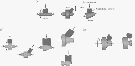
Centerless Grinding
Centerless grinding is a high production process for continuously grinding surfaces in which the workpiece is supported not by centers or chucks, by a blade (figs. 16.1 a and b). Typical parts made by centerless grinding are roller bearings, piston pins, engine valves, camshafts, and similar components.
Parts with diameters as small as 0.1 mm (0.004in.) can be ground. Centerless grinders
Fig. 16-c are now capable of wheel surface speeds on the order of 10000 m/min. using cubic boron nitride abrasive wheels.
Tool and Cutter Grinding
Tool and cutter grinding is the generally complex operation of forming and resharpening the cutting edges of tool and cutter bits, gages, milling cutters, reamers, and so forth.
The grinding wheel for any grinding operation should be carefully chosen and the workpiece set up properly in the grinding machine. Grinding speeds and feeds should be selected for the particular job. Whenever practical, a coolant should be applied to the point of contact of the wheel and the workpiece to keep the wheel and workpiece cool, to wash away the loose abrasive, and to produce a better finish.
In grinding, the speed of the grinding wheel and the feed of the grinding wheel are as important as, and sometimes more important than, proper wheel selection. Occasionally, the grinder spindle should be checked with a tachometer to make sure it is running at its specified RPM. Too slow a speed will result in waste of abrasive, whereas an excessive speed will cause a hard grinding action and glaze the wheel, making the grinding inefficient. The feed of the grinding wheel will determine to a certain extent the finish produced on the work and will vary for different types and shapes of grinding wheels.
Factors Governing Speed
WARNING |
The various factors governing the speed in SFPM of a grinding wheel are as described below.
TABLE 2 Approximate Specific Energy Requirements for Surface Grinding
|
|
Specific energy |
|
Workpiece material |
Hardness |
W-s/mm3 |
hp-min/in.3 |
Aluminum |
150 HB |
7–27 |
2.5–10 |
Cast iron (class 40) |
215 HB |
12–60 |
4.5–22 |
Low-carbon steel (1020) |
110 HB |
14–68 |
5–25 |
Titanium alloy |
300 HB |
16–55 |
6–20 |
Tool steel (T15) |
67 HRC |
18–82 |
6.5–30 |
TABLE 3 Typical Range of Speeds and Feeds for Abrasive Processes
Process variable |
Conventional |
Creep-feed |
Buffing |
Polishing |
Wheel speed (m/min) |
1500–3000 |
1500–3000 |
1800–3600 |
1500–2400 |
Work speed (m/min) |
10–60 |
0.1–1 |
— |
— |
Feed (mm/pass) |
0.01–0.05 |
1–6 |
— |
— |
Work Speed for Cylindrical Grinding
In cylindrical grinding, it is difficult to recommend any work speeds since these are dependent upon whether the material is rigid enough to hold its shape, whether the diameter of the workpiece is large or small, and so forth. Listed below are areas to consider when performing cylindrical grinding:
Work Speed for Surface Grinding
Surface grinding machines usually have fixed work speeds of approximately 50 SFPM or have variable work speed ranges between 0 and 80 SFPM. As with cylindrical grinding, the higher work speeds mean that more material is being cut per surface foot of wheel rotation and therefore more wear is liable to occur on the wheel.
Feeds
The feed of the grinding wheel is the distance the wheel moves laterally across the workpiece for each revolution of the piece in cylindrical grinding or in each pass of the piece in surface grinding. The following methods are recommended for determine feeds:
Depth of Cut
Methods for determining depth of cuts are recommended for determining feeds.
Most grinding machines are equipped with coolant systems. The coolant is directed over the point of contact between the grinding wheel and the work. This prevents distortion of the workpiece due to uneven temperatures caused by the cutting action. In addition, coolant keeps the chips washed away from the grinding wheel and point of contact, thus permitting free cutting.
Clear water may be used as a coolant, but various compounds containing alkali are usually added to improve its lubricating quality and prevent rusting of the machine and workpiece.
An inexpensive coolant often used for all metals, except aluminum, consists of a solution of approximately 1/4 pound of sodium carbonate (sal soda) dissolved in 1 gallon of water.
Another good coolant is made by dissolving soluble cutting oil in water. For grinding aluminum and its alloys, a clear water coolant will produce fairly good results.
TABLE 4 General Recommendations for Grinding Fluids
Material |
Grinding fluid |
Material |
Grinding fluid |
Aluminum |
E, EP |
Refractory metals |
EP |
D: dry; E: emulsion; EP: Extreme pressure; CSN: chemicals and synthetics; MO: mineral oil; FO: fatty oil.
Cylindrical grinding is the practice of grinding cylindrical or conical workpieces by revolving the workpiece in contact with the grinding wheel. Cylindrical grinding is divided into three general operations: plain cylindrical, conical grinding (taper grinding), and internal grinding. The workpiece and wheel are set to rotate in opposite directions at the point of contact.
Plain Cylindrical Grinding
The step-by-step procedure for grinding a straight shaft is given below. The shaft has been roughly turned prior to grinding.
TT = (WW x FF x WRPM)
Where TT |
= Table travel in mm per minute |
WW |
= Width of wheel |
FF |
= Fraction of finish |
WRPM |
= Revolutions per minute of workpiece |
The fraction of finish for annealed steels is 1/2 for rough grinding and 1/6 for finishing; for hardened steels, the rate is 1/4 for rough grinding and 1/8 for finishing.
For example, a l-inch-wide wheel is used to rough grind a hardened steel cylinder with a work RPM of 300.
Table travel = (25.4 x 1/4 x 300) ÷ 100 » 19 m/mint
After the calculations have been completed, set the machine for the proper traverse rate, turn on the table traverse power feed, and grind the workpiece.
Check the workpiece size often during cutting with micrometer calipers. Check the tailstock center often and readjust if expansion in the workpiece has caused excessive pressure against the drilled center in the workpiece.
The finishing cut should be slight, never greater than 0.001 inch, and taken with a fine feed and a fine grain wheel.
If two or more grinding wheels of different grain size are used during the grinding procedure, each wheel should be dressed and trued as soon as it is mounted in the grinding machine.
Conical Grinding
Most conical grinding is performed in the same manner as plain cylindrical grinding. Once the grinding machine is set up, the table is swiveled until the correct taper per inch is obtained. Steep conical tapers are normally ground by swiveling the headstock to the angle of taper. Whichever method is used, the axis of the grinding wheel must be exactly at center height with the axis of the work.
INTERNAL GRINDING
The internal grinding attachment is bolted to the wheel head on the universal tool and cutter grinder. The RPM is increased by placing a large pulley on the motor and a small pulley on the attachment.
The workpiece should be set to rotate in the direction opposite that of the grinding wheel. The following step-by-step procedure for grinding the bore of a bushing is outlined below as an example.
If two or more grinding wheels are used to complete internal grinding, true each wheel after mounting it to the spindle of the internal grinding attachment.
Surface grinding or grinding flat surfaces, is characterized by a large contact area of the wheel with the workpiece, as opposed to cylindrical grinding where a relatively small area of contact is present. As a result, the force of each abrasive grain against the workpiece is smaller than that applied to each grain in cylindrical grinding. In surface grinding the grinding wheel should be generally softer in grade and wider in structure than for cylindrical grinding.
The following sequence is provided as a step-by-step example of a typical surface grinding operation.
A wire wheel mounted to a utility grinding machine is used for cleaning operations such as removing rust, paint, or dirt from metal objects. If the utility grinding machine on which the wire wheel is to be mounted is equipped with wheel guards and tool rests, these parts should be removed or swung out of the way so that the objects to be cleaned can be brought against the wheel without interference.
To clean objects with a wire wheel, place the object firmly against the wire wheel. Work the object back and forth across the face of the wheel until all traces of rust, paint, or dirt are removed. Avoid excessive pressure against the face of the wire wheel to prevent spreading the steel wires. Keep the point of contact below the center of the wheel to avoid kickback of the workpiece.
Polishing, buffing, and lapping are three closely related methods for finishing metal parts. The three different methods of finishing are listed below.
Polishing
Polishing is an abrading process in which small amounts of metal are removed to produce a smooth or glossy surface by application of cushion wheels impregnated or coated with abrasives. Polishing may be used for reduction or smoothing of the surface to a common level for high finish where accuracy is not important, or it may be employed for removing relatively large amounts of material from parts of irregular contour. Rough polishing is performed on a dry wheel using abrasives of No. 60 grain (60 grains per linear inch) or coarser. Dry finish polishing is a similar process where No 70. grain to No. 120 grain abrasives are used. Oiling is the term applied to polishing with abrasive finer than No. 120 grain. In this process, the abrasive is usually greased with tallow or a similar substance.
Buffing
Buffing is a smoothing operation which is accomplished more by plastic flow of the metal than by abrading. The abrasives are generally finer than those used in polishing and instead of being firmly cemented to the wheel are merely held by a "grease cake" or similar substance. Buffing is used to produce a high luster or color without any particular regard to accuracy of dimension or plane. Cut down buffing produces a rapid smoothing action with fast-cutting abrasives and relatively hard buffing wheels. It is accomplished with high speeds and heavy pressures to allow a combined plastic flow and abrading action to occur. Color buffing is the imparting of a high luster finish on the workpiece by use of soft abrasives and soft buffing wheels.
Lapping
Lapping, like polishing, is an abrading process in which small amounts of material are removed. Unlike polishing, however, lapping is intended to produce very smooth, accurate surfaces, and is never used instead of polishing or buffing when clearance is the only consideration. Lapping is accomplished by charging metal forms called laps with flour-fine abrasives and then rubbing the workpiece with the lap. The lap may be of any shape and may be designed to fit into most power machine tools. The only requirements of the lap are that it be of softer material than the material being lapped, and that it be sufficiently porous to accept the imbedded abrasive grain. Common materials for laps are soft cast iron, copper, brass, and lead. Some laps are flat and others are cylindrical to fit on steel arbors for internal lapping of bores. A cutting oil is recommended for most lapping operations.
Polishing and Buffing Speeds
The proper speed for polishing and buffing is governed by the type of wheel, workpiece material, and finish desired. For polishing and buffing in general where the wheels are in perfect balance and correctly mounted, a speed of approximately 1,750 RPM is used for 6-inch to 8-inch wheels; up to 6-inch wheels use 3,500 RPM. If run at a lower rate of speed, the work tends to tear the polishing material from the wheel too readily, and the work is not as good in quality.
Polishing Abrasives
The abrasive grains used for polishing must vary in characteristics for the different operations to which they are applied. Abrasive grains for polishing are supplied in bulk form and are not mixed with any vehicle. The abrasives, usually aluminum oxide or silicon carbide, range from coarse to fine (1 to 20 grains per inch).
Buffing Abrasives
Buffing abrasives are comparatively fine and are often made up in the form of paste, sticks, or cakes; the abrasive being bonded together by means of grease or a similar vehicle. The abrasive sizes for buffing are 280, 320, 400, 500, and 600. Some manufacturers use letters and numbers to designate grain size such as F, 2F, 3F, 4F, and XF (from fine to very fine). Pumice, rottenstone, and rouge are often used as buffing abrasives.
Lapping Abrasives
Only the finest abrasives are used for lapping. These may be either natural or artificial. Abrasives for lapping range from No. 220 to No. 600 or No. 800 which are very fine flours. Lapping compounds are generally mixed with water or oil so that they can be readily applied to the lap.
Source: http://faculty.ksu.edu.sa/hossainy/Book1/Grinding.doc
Web site to visit: http://faculty.ksu.edu.sa/
Author of the text: indicated on the source document of the above text
If you are the author of the text above and you not agree to share your knowledge for teaching, research, scholarship (for fair use as indicated in the United States copyrigh low) please send us an e-mail and we will remove your text quickly. Fair use is a limitation and exception to the exclusive right granted by copyright law to the author of a creative work. In United States copyright law, fair use is a doctrine that permits limited use of copyrighted material without acquiring permission from the rights holders. Examples of fair use include commentary, search engines, criticism, news reporting, research, teaching, library archiving and scholarship. It provides for the legal, unlicensed citation or incorporation of copyrighted material in another author's work under a four-factor balancing test. (source: http://en.wikipedia.org/wiki/Fair_use)
The information of medicine and health contained in the site are of a general nature and purpose which is purely informative and for this reason may not replace in any case, the council of a doctor or a qualified entity legally to the profession.
The texts are the property of their respective authors and we thank them for giving us the opportunity to share for free to students, teachers and users of the Web their texts will used only for illustrative educational and scientific purposes only.
All the information in our site are given for nonprofit educational purposes