
Injection molding is a mass conserving (MC) process in which thermoplastic material is fed into a heated barrel, mixed, and molten plastic is forced into a mold cavity where it cools and hardens to the configuration of the mold cavity, which is the inverse of the desired shape. Injection molding is very widely used for manufacturing a variety of parts, from the smallest component to entire body panels of cars. Hence this unit process life cycle inventory (uplci) is to establish representative estimates of the energy consumption and overall environmental impact from the injection molding unit process. The injection molding unit process life cycle inventory (uplci) profile is for a high production manufacturing operation, defined as the use of processes that generally have high automation and are at the medium to high throughput production compared to all other machines that perform a similar operation. This is consistent with the life cycle goal of estimating energy use and environmental impact representative of efficient product manufacturing. Injection Molding is a cyclic process with variation of load through-out the cycle. The variation of the load depends on several factors of the mould design (final part shape), polymer used and process parameters set. Therefore presentation of overview of energy consumption becomes quite complex.
Injection molding is one of the most widely used and versatile methods of polymer processing. The process begins as solid polymer beads are feed from a hopper into the heated barrel of an injection molding machine. The polymer is plasticized in the barrel by the heat provided by heater bands and through shear forces exerted on the polymer by the turning of a screw in the barrel. Figure 1 shows the heating barrel and injection unit of a typical injection molding machine. Once enough polymers have been melted in the barrel, the screw also acts as a ram to inject the polymer into a cooled and pressurized mould. The injection molding process in most new machines is electrically controlled by a built-in computer and the motors are electrically driven. The choice of injection molding machine type (hydraulic, hybrid or electric) has a substantial impact on the specific energy consumption (SEC). The conventional measure of process energy use is the SEC, which is expressed as the number of kWh used to process 1 kg or lb of material (kWh/kg or kWh/lb). SEC is the ratio of energy consumed per molding cycle to the weight of molded part in kg. This ratio could be maintained as low as possible provided efficiency aspects of machine selection pump and controls are understood while setting the machine. The SEC values for hydraulic, hybrid and electric machines are 5.3, 3.7 and 3.5 kWh/kg respectively (Thirez Thesis). In electric machines the hydraulic elements are replaced, so there is no problem in hydraulic oil leakage and pollution, so is the operation noise. There are savings in energy and electric power consumption is lower. It is of higher accuracy than ordinary hydraulic injection molding machine with highly clean.
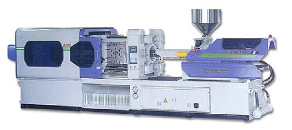
Figure MC2.1 Injection Molding Machine (Photograph from Insurtech International Corp. Europe.)
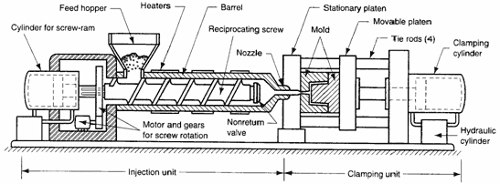
Figure MC2.2 Injection Molding Process Schematic (Todd et al., 1994)
Figure MC2.3 shows an overview of the developed environmental-based factors for injection molding forming process. During the operation, energy is input to an electrically driven injection molding machine in the form of electricity supplied to the heater bands, the electric motors and the electric controls. Energy is lost from the system in the form of motor losses, radiation and convection from the heater bands, cooling losses, and as an increase in the enthalpy of the formed plastic. The polymer demands specific kilo calories of heat for changing its state from solid to melt. The required heat comes from shear action in the compression zone of the screw, the heat-in-put through pre-heating and the heat-in-put through heaters on the barrel. One servo motor rotates the screw, another moves the screw along the axis and a third moves the toggle clamp to open and close the mold. Injection molding machines consists mainly two parts: the injection unit and the clamping unit which can be seen Figure MC2.2. Injection pressures can range from 3 to 2000 MPa and clamp tonnage from 5 to 10,000 tons (Muccio, 1994).
The injection molding machine injects molten plastic into a mold piece. The plastic then cools, as it is packed into the mold. The entire process of an injection molding machine cycle can be broken down into four main energy consuming phases: plasticizing, injecting, cooling and clamping/unclamping. All four parts of the cycle perform different operations and have different pressure requirements, meaning that they have different power consumption. Because high production injection molding is a semi-continuous process, the lci is based on a representative operational sequence, in which
Waste energy is the energy consumed by the machine that does not go into the formation of the part. Furthermore, during the actual production of parts, energy is lost through different ways. For example, during the heating process, the heater not only heats the plastic, but also heats the environment as well. This results in energy that does not go into the production of the part, but that is lost to the environment. Other losses include heated plastic that is not injected into the mold and the excess clamping pressure beyond that absolutely needed to keep the mold pressed together. The minimum energy needed to create the product can be calculated by considering the mass of polymer needed for one part and determining the energy needed to first heat the plastic to liquid form, then transition it into the shape of the part, and finally the energy to cool the part. Thus, the energy wasted in the actual production of the part is the difference between the energy used in production and the energy calculated for the production of the part.
Thermoplastic Yield Strength Elastic Modulous Heat deflection
(MN/m2) (MN/m2) Temp (0C)
High density
Polyethylene 23 925 42
High impact
Polystyrene 20 1,900 77
Acrylonitrile-
butadiene styerene (ABS) 41 2,100 99
Acetal 66 2,800 115
Polyamide 70 2,800 93
Polycarbonate 64 2,300 130
Polycarbonate
(30% glass) 90 5,500 143
Modified
Polyphenylene
Oxide (PPO) 58 2,200 123
Modified PPO
(30% glass) 58 3,800 134
Polypropylene
(40% talc) 32 3,300 88
Polyester
Teraphtalate
(30% glass) 158 11,000 227
The energy consumption of brake forming is calculated as follows.
Etotal = Pbasic * (tbasic ) + Pidle * (tidle) + Pbrakeforming * (tbrakeforming) (1)
where power and time are illustrated in Figure MC1.5.
An approximate importance of the many variables in determining the brake forming energy requirements was used to rank parameters from most important to lower importance as follows:
From this parameter list, only the top 5 were selected for use in this unit process life cycle with the others having lower influence on energy. Energy required for the overall brake forming process is also highly dependent on the time taken for idle and basic operations.
Table MC1.2. Typical tensile strengths of some materials (Tschatsch, 2006)
Material |
Tensile strength, Psi (Mpa) |
||
Soft |
Hard |
||
Lead |
3625-5800 (25-40) |
- |
|
Tin |
5800-7250(40-50) |
- |
|
Aluminum (99.0%) |
13,350(92) |
246,564(1700) |
|
High-tension aluminum alloy Type 4 |
32,640(225) |
69,618(480) |
|
Duralumin |
36,990(255) |
69,618(480) |
|
Zinc |
21,755(150) |
36,260(250) |
|
Copper |
31,183-39,885(215-275) |
43,511-58,015(300-400) |
|
Brass (70:30) |
47,140(325) |
76,870(530) |
|
Brass (60:40) |
53,950(372) |
71,068(490) |
|
Phosphor bronze |
58,015-72,518(400-500) |
72,518-108,778(500-750) |
|
Bronze |
58,015-72,518 (400-500) |
72,518-108,778 (500-750) |
|
Nickel silver |
50,763-65,266(350-450) |
72,518-101,526 (550-700) |
|
Cold rolled iron sheet |
46,412-55,115(320-380) |
- |
|
Steel, 0.1%C |
46,412(320) |
58,015(400) |
|
Steel, 0.2%C |
58,015(400) |
72,518(500) |
|
Steel, 0.3%C |
65,266(450) |
87,023(600) |
|
Steel, 0.4%C |
81,221(560) |
104,427(720) |
|
Steel, 0.6%C |
104,427(720) |
130,534(900) |
|
Steel, 0.8%C |
130,534(900) |
159,542(1100) |
|
Steel, 1.0%C |
145,038(1000) |
188,550(1300) |
|
Silicon steel sheet |
79,770(550) |
92,275(650) |
|
Stainless steel sheet |
92,275-101,526(650-700) |
- |
|
Nickel |
63,816-72,518(440-500) |
82,672-91,374(570-630) |
|
Table MC1.3. Recommended minimum bend radius for commercial quality steel sheet, strip and plate (Groover, 2003)
Material |
Soft |
Hard |
Aluminium alloys |
0 |
6T |
Brass, low leaded |
0 |
2T |
Magnesium |
5T |
13T |
Steels: low C, low alloy and HSLA |
0.5T |
4T |
Austenitic stainless steels |
0.5h |
6T |
Titanium |
0.7T |
3T |
Titanium alloys |
2.6T |
4T |
Energy-consuming peripheral equipments included in idle power (Pidle) are shown in Table MC1.1. The idle power characterizes the load case when there is relative movement of the tool and the work-piece without changing the shape of the body (e.g. axis movement) - Handling. For brake forming, the handling times are the air time of approach and retraction after forming. The idle time (tidle) is the sum of the handling time (thandling) and the brakeforming time (calculated above as tforming, equation 2), see Figure MC1.5. For brake forming machines, the handling times are the air time of approach and retraction after forming. We can calculate the handling times and energy as follows.
Idle energy = [timehandling + timeforming]* Pidle (7)
During the brake forming process the punch is considered to be at an offset of at least 6 times the thickness of workpiece. Every time while brake forming the punch comes down from a height of 6 times the thickness of the workpiece and again retraces back to an offset position after completing the process. Approach time is 6T divided the approach speed, which depends on machine specification. While the retraction time may be longer than the brake forming time, this is estimated as the sum of the approach and brake forming times and divided by the return speed, which depends on the machine specification
Time for handling is
Approach + retraction times = timehandling (8)
timehandling= (6T)/Approach speed + (6T+D)/return speed
The brake forming time was previously calculated, equation 2
timeidle = thandling + tforming (9)
From these calculations the idle energy for a single hole is
E (Joule/bend) = (tapproach + tretraction) + tforming]* Pidle (10)
The average idle power Pidle of automated CNC press brake machines is between 1,200 and 15,000 watt*. (* This information is from the CNC manufacturing companies, see Appendix 1). Approximately Handling time will vary from 0.1 to 10 min.
The basic energy of a press brake is the demand under running conditions in “stand-by mode”. Energy-consuming peripheral equipments included in basic energy are M1, M2 and PC from Table MC1.1. There is no relative movement between the tool and the work-piece, but all components that accomplish the readiness for operation (e.g. machine control unit (MCU), unloaded motors, servo motors, pumps) are still running at no load power consumption. Most of the automated CNC press brake machines are not switched off when not forming and have a constant basic power.
The average basic power Pbasic of automated CNC press brake machines is between 800 and 8,000 watt* (* From CNC press brake manufacturing companies the basic power ranges from 1/8th to 1/4th of the maximum machine power, (see Manufacturers Reference Data in Appendix). The largest consumer is the hydraulic power unit.
Ostwald, 1986 has shown that the time to load a blank or part into a press and then remove the part is proportional to the perimeter of the rectangle which surrounds the part. This time can be given by tload/unload = 3.8 + 0.11 (L + W) (seconds)
Where L, W = rectangular envelope length and width, cm.
From Figure MR 1.5, the basic time is given by
Tbasic = tload/unload + thandling + tforming (11)
where thandling + tforming = tidle as determined in equation 9.
With only the following information the unit process life cycle energy for brake forming can be estimated.
For ordinary press-brake operations such as bending and simple forming, coolant oil is less commonly used. Hydraulic press brakes use fluid power to do work. In this machine, high pressure liquid called hydraulic fluid is transmitted throughout the machine to various hydraulic motors and hydraulic cylinders. In addition to transferring energy, hydraulic fluid needs to lubricate components, suspend contaminants and metal filings for transport to the filter, and to function well to several hundred degrees Fahrenheit. Hydraulic fluid replacement occurs so infrequently that on per bend or per 1,000 bend basis, this mass loss is neglected.
Lubricant oil is commonly (but not always) used on the metal surface in contact with the die. Lubricant is applied along the bend line and then is some subsequent processing step, it is removed before a final product is used. In order to link this mass loss directly to brake forming, it is included here. Note the energy or ancillary waste for lubricant removal (solvent degreasing, rag wipe, etc) would be captured in the uplci of those processes and only the lubricant mass is assigned to brake forming. Lubricant applied and removed is estimated (Madavan, Wichita State University, 2009, personal communication) as 5cm width x L (cm) x (2.54/1000) cm thickness x 0.9 g/cm3 = 0.11 g/cm length of bend.
In this report we analyze the detailed energy consumption calculations in brake forming process. The forming process is performed on BAILEIGH CNC press brake machine (BP – 5060). The machine specifications are listed below:
Table MC 1.4. Machine specification
Specifications |
BAILEIGH |
Model Number |
BP-5060 |
Max. Bending force, kN |
500 |
Approach Speed, in/sec |
3.15 |
Bending Speed, in/sec |
0.28 |
Return Speed, in/sec |
2.4 |
Main motor, kW |
3.7 |
Motor 2, kW |
0.4 |
3 Axes motor output(X,Y,Z), kW |
0.75 |
Total Maximum Power consumption |
6kW |
For this example we are assuming a stainless steel (soft) sheet as the work piece. The work piece is of sheet-metal part of 3mm thick and 20mm bend length is bent to an included angle of α = 1200 and a bend radius of 7.5 mm in a V-die. The objective of the study is to analyze the energy consumption in press brake machine. The die opening is 24 mm. The metal has tensile strength of 675 Mpa.
The forming conditions and the process parameters are listed in Table MC1.5.
Table MC1.5. Process Parameters for Example Case
Process Conditions |
|
Sheet thickness (T) |
0.12 in |
Ultimate Tensile strength (UTS) |
96,900 psi |
Die opening (W) |
0.94 in |
Bend angle (A) |
120 deg |
Bend radius (R) |
0.30 in |
Bend Length (L) |
0.79 in |
Die closed depth, D |
0.27 in |
During forming operation the tool is considered to be at an offset of 18mm (6 times the workpiece thickness) above the workpiece. During brake forming the tool comes down from a height of 18mm. It retracts (D+18) mm back to the offset position after completing the forming process.
The total processing time can be divided into the 3 sub groups of basic, idle, and brake forming time.
Brake forming time:
The time for bending is determined by
tforming = (D)/V (sec)
Where V is the bending speed in mm/sec, and D is the die depth in mm.
D = depth of close die = 0.28 in (0.12*2.3, see page 9)
V = 0.28 in/sec
Time to bend will be,
tforming = (0.28 in)/0.28 in/sec)
= 1 sec/bend
Energy required for each bend,
E = D * F
The force required to bend a 20-mm long sheet of soft stainless steel 3mm thick can be estimated using the following calculation:
F = S L T2 K/ W
F = 96,900 psi * (0.79) * (0.12)2 * 1.33 = 1,560 lbf = 7,000 N
0.94
Brake forming energy for each bend,
E = 7,000 N * 0.0069 m = 0.048 kJ
Power required P = F * V
= 7,000 * 0.007 = 0.0.049 kW/bend
Handling Time:
The air time for bending is approach and retract time
Approach time = 18/80 = 0.225 sec
Retracts time = (18 + D) /60 = 24.9/60 = 0.415 sec
Total air time = 0.64 sec
Total idle time = tbf + tair
= 1 + 0.64 = 1.64 sec
Idle power from Appendix 1 can be assumed as = 2.5 kW
Idle energy = 2.5 * 1.64 = 4.125 kJ/bend
Basic time:
Loading and unloading time t = 3.8 + 0.11 (L + W)
= 3.8 + 0.11 (2 + 5)
= 4.57 sec = tl/u
Pbasic = 1.25 kW
Ebasic = Pbasic * tbasic
Tbasic = tl/u + tidle = 4.57 + 1.64 = 6.2 sec
Ebasic = 1.25 * 6.2 = 7.8 kJ/bend
Total Energy
Etotal = 0.207 + 4.125 + 7.8 = 12 kJ/bend
Mass Loss
Lubricant loss is 0.011 g/cm length *2 cm length = 0.022 g lubricant loss/bend
This report presented the models, approaches, and measures used to represent the unit process life cycle inventory (uplci) of brake forming operations. The only major environmental characteristics are is the energy consumption of the press brake and lubricant loss. Calculations for product manufacturing are presented, based on knowing only the bend length and the material bent. The life cycle of brake forming is based on a typical high production scenario (on a CNC press brake machine) to reflect industrial manufacturing practices.
The energy can be calculated from a basic list of variables, likely to be known for each part to be brake formed
The methodology that has been followed for collecting technical information on CNC machines has been largely based in the following:
The documentation of the CNC press brake and the technical assistance collected from the manufacturing companies through the internet. Several interviews with the service personnel of the different CNC manufacturing companies have been carried out. After collecting the information from the different companies it has been put together in the relevant document that describes the different approaches the different companies have regarding the technical information on the CNC press brake machine. Telephone conversations allowed us to learn more about basic power and idle power. Companies that involved in our telephone conversations are Baileigh, Ronmack, Trumpf and Cincinnati. These companies manufacture different sizes of CNC machines, but this report shows the lower, mid and highest level of sizes. For our case study we picked machine at the mid level.
Specifications |
BAILEIGH |
||
Model Number |
BP-3360 |
BP-5060 |
BP-9078 |
Bending force, kN |
330 |
500 |
900 |
Approach Speed, mm/sec |
80 |
80 |
80 |
Bending Speed, mm/sec |
7 |
7 |
7 |
Return Speed, mm/sec |
60 |
60 |
60 |
Main motor, kW |
2.2 |
3.7 |
7.4 |
Motor 2, kW |
0.4 |
0.4 |
0.4 |
3 Axes motor output(X,Y,Z), kW |
0.75 |
0.75 |
0.75 |
Specifications |
RONMACK |
||
Model Number |
RM-2050 |
RM-3100 |
RM-8000 |
Bending force, kN |
600 |
1500 |
5000 |
Approach Speed, mm/sec |
120 |
120 |
120 |
Bending Speed, mm/sec |
9 |
9 |
9 |
Return Speed, mm/sec |
100 |
80 |
80 |
Main motor, kW |
5.5 |
11 |
37 |
Motor 2, kW |
1 |
1 |
1 |
3 Axes motor output(X,Y,Z), kW |
1 |
1 |
1 |
Specifications |
TRUMPF |
||
Model Number |
TB V-50 |
TB V-130 |
TB V-320 |
Bending force, kN |
560 |
1440 |
3570 |
Approach Speed, mm/sec |
150 |
150 |
150 |
Bending Speed, mm/sec |
12 |
12 |
12 |
Return Speed, mm/sec |
120 |
120 |
120 |
Main motor, kW |
6 |
18 |
35 |
Motor 2, kW |
1 |
1 |
1 |
3 Axes motor output(X,Y,Z), kW |
1 |
1 |
1 |
Specifications |
CINCINNATI |
||
Model Number |
90MX6 |
175MX10 |
350MX12 |
Bending force, kN |
500 |
1200 |
4000 |
Approach Speed, mm/sec |
300 |
275 |
250 |
Bending Speed, mm/sec |
30 |
25 |
20 |
Return Speed, mm/sec |
200 |
180 |
150 |
Main motor, kW |
15 |
20 |
25 |
Motor 2, kW |
2 |
2 |
2 |
3 Axes motor output(X,Y,Z), kW |
1 |
1 |
1 |
Source: http://cratel.wichita.edu/uplci/wp-content/uploads/2010/03/MC2-Injection-Molding-10-11-2009.doc
Web site to visit: http://cratel.wichita.edu
Author of the text: indicated on the source document of the above text
If you are the author of the text above and you not agree to share your knowledge for teaching, research, scholarship (for fair use as indicated in the United States copyrigh low) please send us an e-mail and we will remove your text quickly. Fair use is a limitation and exception to the exclusive right granted by copyright law to the author of a creative work. In United States copyright law, fair use is a doctrine that permits limited use of copyrighted material without acquiring permission from the rights holders. Examples of fair use include commentary, search engines, criticism, news reporting, research, teaching, library archiving and scholarship. It provides for the legal, unlicensed citation or incorporation of copyrighted material in another author's work under a four-factor balancing test. (source: http://en.wikipedia.org/wiki/Fair_use)
The information of medicine and health contained in the site are of a general nature and purpose which is purely informative and for this reason may not replace in any case, the council of a doctor or a qualified entity legally to the profession.
The texts are the property of their respective authors and we thank them for giving us the opportunity to share for free to students, teachers and users of the Web their texts will used only for illustrative educational and scientific purposes only.
All the information in our site are given for nonprofit educational purposes