Welcome to this section of your course which is designed to enable you the learner, install domestic lighting circuits.
By the end of this unit you will be able to:
Understanding this information will allow you read a drawing showing location of lighting accessories, switches etc. in a domestic installation. You will be able to read a circuit drawing showing lighting points controlled by 1 Way, Selective, 2 Way, and 2 Way and Intermediate switching.
Architectural
Distribution board |
|
One-Way Switch ( Single Pole ) |
|
Two-Way Switch ( Single Pole ) |
|
Intermediate Switch |
|
Lamp, general symbol |
|
Spotlight |
|
One Way Pull Cord Switch ( Single Pole ) |
|
One-Way Switch with Pilot Lamp |
|
One-Way Period Limiting Switch |
|
Lighting Outlet Position |
|
|
||||
|
Lighting Outlet on Wall |
|
||||
|
Fan |
|
||||
|
Joint Box |
|
||||
|
Time Switch |
|
||||
Circuit
Fuse |
|
Isolator |
|
Fuse Isolator |
|
Fuse Switch |
|
Miniature Circuit Breaker ( MCB ) |
|
One-Way Switch ( Single Pole ) |
|
Two-Way Switch ( Single Pole ) |
|
Intermediate Switch |
|
Conductors Crossing |
|
Conductors Crossing |
|
Earth |
|
Wiring System: An assembly made up of cables or busbars and the parts that secure, and if necessary enclose, the cables or busbars.
DSO: The distribution system operator.
Main Supply Point ( origin of an installation ): The point at which the supply is connected to an installation.
Nominal Voltage: A voltage by which an installation, or part of an installation, is designated.
Low Voltage: A nominal voltage exceeding 50 V AC or 120 V DC but not exceeding 1000 V AC or 1500 V DC.
Extra Low Voltage: A nominal voltage not exceeding 50 V AC or 120 V DC between conductors or between a conductor and earth.
Isolation ( isolating function ): Function intended to cut off the supply from all or a discrete section of the installation by separating the installation or section from every source of electrical energy for reasons of safety.
Isolating Switch: A mechanical switching device that, in the open position, complies with the requirements specified for the isolating function.
Main Isolating Switch: A switching device provided at the main supply point for the purpose of isolating an installation.
Switchgear: Equipment provided to be connected to an electrical circuit for the purpose of carrying out one or more of the following functions: protection, control, isolation, switching.
Distribution Board: An assembly of protective devices, including two or more fuses or circuit breakers, arranged for the distribution of electrical energy to final circuits or to other distribution boards.
Circuit: Part of an electrical installation supplied from the same origin and protected against overcurrents by a single protective device.
Current Using Equipment: Equipment intended to convert electrical energy into another form of energy, for example light, heat or motive power.
Final Circuit: A circuit connected directly to current using equipment or to socket outlets.
Point ( in wiring ): A termination of the fixed wiring intended for the connection of current-using equipment.
Luminaire: Apparatus that distributes, filters or transforms the light transmitted from one or more lamps and includes all the parts necessary for supporting, fixing and protecting the lamps and where necessary, circuit auxiliaries together with the means for connecting them to the supply. It does not include the lamps themselves.
Main Earthing Terminal ( MET ) or Bar: A terminal or bar provided for the connection of protective conductors, main equipotential bonding conductors and conductors for functional earthing if any, to the means of earthing.
Live Part: A conductor or conductive part intended to be energised in normal use, including a neutral conductor, but not a PEN conductor.
Sequence of Control
The electricity supply to a domestic installation begins at the meter cabinet which houses the DSO service fuse, DSO meter and an isolator. This is the Main Supply Point.
The DSO supply cable is referred to as the service cable. The DSO service fuse and meter are sealed to prevent any interference with this part of the installation. The Nominal Voltage of the supply to domestic premises is 230 Volts. This is known as Low Voltage.
The control and distribution of the electricity supply to the installation is contained within one enclosure. It is referred to as a Distribution Board. This unit has its own main switch fuse, or a separate main switch and main fuse, or main MCB. This is followed by individual circuit fuses or more commonly nowadays, Miniature Circuit Breakers ( MCB’s ), to protect and isolate each circuit. There will also be neutral and earth terminals provided. See Figure 1.
Distribution Board |
Figure 1.
The distribution board may also house other protective or control devices such as Residual Current Devices ( RCD’s ), bell transformers, time-switches and contactors.
Figure 2 represents the sequence of control for a very basic distribution board. Depending on the installation requirements, a second or third RCD may be required and of course, more MCB’s, one for each circuit.
|
Figure 2.
As can be seen, an RCD is not provided for the lighting and cooker circuits, although there are exceptions to this situation.
Under the broad heading above, there are basically two types of installation involved:
Flush Mounted Installation
This is the most popular method of installation used in domestic premises, because all cables, switch boxes, socket boxes etc, are concealed in the walls, floors and ceilings.
The job of wiring a house is done in two distinct stages.
Stage One, referred to as the ‘first fixing’, involves:
After this stage nothing more can be done until all ceilings and walls are plastered and skimmed.
Stage Two, referred to as the ‘second fixing’ involves:
Flush mounted installations are covered in Phase 2 by the use of a simulated plasterboard partition to which certain flush mounted boxes can be attached. All other work will be as for a surface mounted installation.
Surface mounted installations are used in various situations such as:-
A surface mounted installation in domestic / commercial situations normally involves the use of conduit or trunking. It is not unusual to see a combination of flush and surface work together, cables being concealed where possible and mounted on the surface where concealment is not possible.
PVC / PVC cables are normally used in surface mounted installations, as they can be installed directly on a surface, in a building void, in conduit, or in trunking.
Surface type boxes are used rather than flush types. Switches, sockets etc. are the same for both surface and flush types of installation.
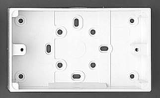
Surface switch boxes are about 20mm deep and white in colour, to match the type of switch used. The boxes have knock-outs for cable entry on all four sides and also in the base. These knockouts should be carefully cut out using a junior hacksaw, to suit the cable being installed. The boxes may be fixed directly to a surface using countersunk woodscrews placed through slotted holes for easy alignment, or directly to a round flush mounted conduit box.
Figure 3 illustrates a single surface mounted box, which can accommodate either 1, 2 or 3 gang switches. The double surface mounted box, shown in Figure 4, can accommodate either 4 or 6 gang switches.
|
|
Figure 3 Figure 4
Switches
The type of switch used in domestic installations is called a plate switch. Figure 5 illustrates a 1 gang 1 way plate switch. One gang refers to the fact that there is only one switch in the plate. One-way indicates that it is a one-way switch, two-way and intermediate switches are also available.
These switches are usually rated at 5 or 6 Amps, and intended for use on AC circuits only. They are rocker type switches and the operating principle of a 1 way single pole switch is shown in Figure 6.
Single pole means that there is only one contact. The contact must be used to break the phase conductor. If the number of poles is not mentioned for a particular switch, then it is assumed to be a single pole switch. Double pole switches are also available.
This type of switch has a centre-pivoted dolly. This dolly operates a contact, through a spring loaded, ball and socket mechanism. When the rocker is pressed to the ‘down’ position, the contact closes and when pressed to the ‘up’ position, the contact opens.
|
Figure 6.
Switch Terminal Identification
Figure 7 illustrates a 1 Gang 1 Way Single Pole switch, it has only two terminals. The phase conductor or switch feed is connected to the top terminal and the output conductor or switch wire is connected to the bottom terminal. If the opposite is done then the switch will still control the circuit. The switch should be fitted the right way up as indicated by the information on the back of the switch.
|
Figure 7.
Figure 8 illustrates a 1 Gang 2 Way Single Pole switch, it has three terminals. The switch feed is normally connected to the common terminal and the switch will then give an output on either the L1 or L2 terminal. If there is more than one switch mounted on the plate, the wiring will be more complicated. It is best to simply identify each switch as a separate item.
|
Figure 8.
Figure 9 illustrates an intermediate switch, it has four terminals. This is a more complicated switch and will be dealt with later on.
|
Figure 9.
Switch Gang and Way Identification
Figure 10 illustrates a 1 Gang Plate switch; it may be a 1 Way, 2 Way, intermediate or double pole type.
Example:
1 Gang 1 Way Plate Switch
1 Gang 2 Way Plate Switch
1 Gang Intermediate Plate Switch
1 Gang Double Pole Plate Switch
|
Figure 10.
Figure 11 illustrates a 2 Gang 2 Way Plate Switch. Two gang one way switches may not always be available, in this event two gang two way plate switches are generally used. This also applies to 3, 4 and 6 Gang switches.
|
Figure 11.
Figure 12 illustrates a 3 Gang 2 Way Plate Switch.
|
Figure 12.
Figure 13 illustrates a 4 Gang 2 Way Plate Switch; a double box is required for this switch.
A 6 Gang 2 Way Plate Switch is also available
Lampholders
Figure 14 illustrates a standard Bayonet Cap ( BC ) lampholder. BC lampholders are normally found in domestic installations. They are also available with a long shield. The shield, which is screwed on, is also used to retain any lampshade, which may be fitted.
Figure 15 illustrates a partly sectioned BC lampholder with the shield removed. BC lampholders are designed for quick and easy lamp removal and replacement. However, they must hold the lamp in firm electrical contact to prevent the lampholder from overheating. Connecting pins, which are spring loaded help, achieve this. A good cord grip is also an essential feature of lampholders and this must be properly utilised in order to take the strain of a possibly heavy lampshade, away from the flex terminations.
|
Figure 15.
Batten Lampholders
There are a variety of batten type lampholders on the market. The following is a sample of some of these.
Figure 16 illustrates a straight batten lampholder fitted with a ‘short shield’. This shield provides protection against touching of the lamp cap. The batten lampholder has no backplate and therefore cannot be mounted directly on a surface without the use of a suitable base or box. Batten lampholders may have two or three terminals present.
|
Figure 16.
Figure 17 illustrates an angle batten lampholder fitted with a long shield. It is also available with a short shield fitted. The long shield affords better protection against touching of the lamp. They have limited use in a modern installation.
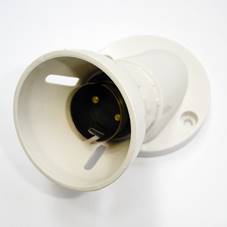
Figure 17.
Figure 18 illustrates a mounting block for use with batten lampholders where necessary.
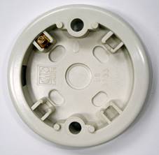
Figure 18.
Figure 19 illustrates a straight batten lampholder with an integral backplate fitted. This type of batten lampholder may have three or four terminals, and can be mounted directly on a surface. Cable entry is via the backplate.
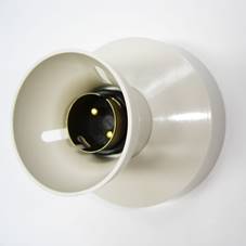
Figure 19.
IMPORTANT: Batten lampholders, without an integral backplate, may not be mounted directly on a surface.
Ceiling Roses
There are basically two types of ceiling rose available, although there is a wide range of makes and shapes. The two types are the Two-Plate Ceiling Rose, which has two terminals and the Three-Plate Ceiling Rose, which has three terminals. Both were developed for use on different wiring systems. Older types of ceiling roses were developed at a time when it was not necessary to provide an earth at lighting points. It is now essential to provide an earth, and so an earth terminal is now included on all ceiling roses. This in effect means that a Two-Plate Ceiling Rose has a third terminal fitted, whilst a Three-Plate Ceiling Rose has four terminals.
Figure 20 illustrates one of the original types of Two-Plate Ceiling Rose. The earth terminal is marked “E” and the two unmarked terminals are used for the neutral and the switch wire. There must also be a cord grip provided similar to that in a lampholder.
|
Figure 20
Figure 21 illustrates a Three-Plate Ceiling Rose. The additional terminal, marked L, is for the Phase or ‘Live’ conductor, which is present in a lighting system wired using the Three-Plate Ceiling Rose Method.
|
Figure 21.
Figure 22 illustrates a modern type Three-Plate Ceiling Rose which has been designed to minimise installation time, and maximise safety of the installer and the end user. Each of the four terminal blocks have three individual terminal screws. It caters for the connection of twelve conductors.
|
Figure 22.
Figure 23 illustrates a lampholder connected to a ceiling rose. The complete unit is called a pendant. The flex connecting the lampholder to the ceiling rose should be a minimum of 0.5mm2. Heat Resisting White Circular PVC type is recommended.
Pendants are available from certain manufacturers in a range of flex length. This allows installations to be completed more efficiently.
Figure 24 illustrates a plug-in type ceiling rose and safety lampholder, which can be easily removed without leaving exposed conductors. The safety lampholder incorporates contacts, which are automatically disconnected from the supply, when the lamp is removed.
|
Figure 24.
The table below set out the maximum weight, which can be supported by some common, flex sizes.
Flex |
Max. Weight |
0.5mm2 |
2 kg |
0.75mm2 |
3 kg |
1.0mm2 |
5 kg |
Switching Circuits
One-Way Switching Circuit
Figure 25 shows how a lamp is controlled by a simple one-way switch, providing on / off control of the lamp. The phase conductor is connected to the one-way switch, terminal C, through a suitably rated fuse or MCB, 6-10A. The neutral is connected directly to the lamp.
When the switch is closed the phase conductor is switched through to the lamp from terminal L1 and the 230 V supply is placed across the terminals of the lamp and so the lamp is illuminated.
When the switch is opened the phase conductor is interrupted and the lamp is extinguished. This occurs when the switch is in the “up” position.
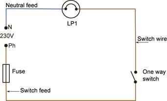
Figure 25.
If more than one lamp is required, the extra lamp or lamps should be connected in parallel as shown in Figure 26.
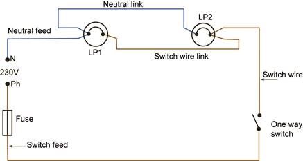
Figure 26.
Selective Switching Circuit
In Figure 27 a one-way switch is providing simple on / off control of the supply to a selector switch. This selector switch has two outputs. One of these outputs is used to feed lamp LP1, while the other feeds lamp LP2.
When the one-way switch is placed in the “on” position, either LP1 or LP2 will illuminate. When the selector switch is positioned as shown, LP1 will be “on” and LP2 will be “off”. If it is switched to the position shown by the dotted line, LP1 will be “off” and LP2 will be “on”.
In this way, one can select which lamp is “on” and which lamp is “off”. Both lamps cannot be “on” at the same time. This circuit was once used to provide two levels of lighting in certain circumstances. If LP1 were a 15 Watt lamp, it would provide a very low level of illumination in, say a child’s bedroom or a hospital ward. LP2 might, on the other hand, be a 100 Watt lamp and provide a high level of illumination.
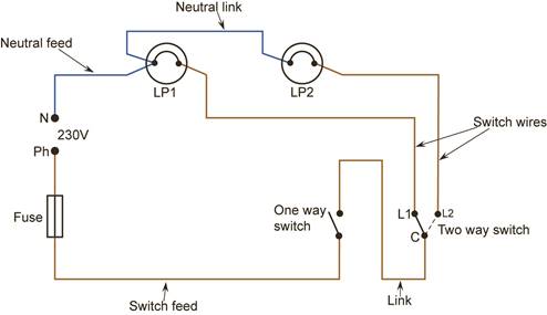
Figure 27.
Two-Way Switching Circuit
Figure 28 shows how a lamp can be controlled from two locations providing on / off control from either location. This circuit is used to control lamps in such places as stairways, corridors and rooms with two doorways.
The two-way switch has two outputs, sometimes labelled L1 and L2. The third terminal is referred to as the “Common” terminal and is marked “C” in some cases. This terminal is “common” to L1 & L2. In the “up” position the common is connected to L2 as shown, and therefore the lamp is “off”. If either switch is changed to the L1 position the lamp will be “on”. If both switches are changed to the L1 position the lamp will again be “off”. If the “strappers” are crossed over at either switch, the lamp will be “on” when both switches are in the “up” position. It is simply good practice to ensure that this does not occur. This means that it is possible to place all switches in the “up” position and be assured that all lamps are “off”. It also ensures safety when replacing faulty lamps or flex drops.
Figure 29 shows an alternative method of providing two-way switching. It is used to best advantage when a conversion from one-way to two-way control is required. Existing cables can be used without the unwanted extra connection at switch A, which would be required if the standard method was used.
Two-Way and Intermediate Switching Circuit
Figure 30 shows how a lamp can be controlled from three locations, providing on / off control from each of these locations. This circuit is used to control lamps in such places as stairways with more than one landing, long corridors and rooms with more than two doorways. If more than three switching locations are required it is simply necessary to add in extra intermediate type switches, at these locations.
The intermediate switch has four terminals. These terminals may be labelled in different ways, few of which are of any benefit to the installer. To complicate matters, there are two distinct types of intermediate switch. The more common type is shown in Figure 31. To consider how it functions we will number the terminals as follows:
In the “up” position terminals 1 and 2 are connected to terminals 3 and 4 respectively.
In the “down” position terminals 1 and 2 are connected to terminals 4 and 3 respectively.
If we apply this information to the circuit above we can see that the lamp is “off”. By operating the intermediate switch, the lamp can be switched “on”. The two two-way switches operate as previously described. Other makes of intermediate switch may operate the opposite way round.
The other, less common type of intermediate switch operates as shown in Figure 33.
‘Up’ position
‘Down’ position
In the “up” position terminals 1 and 2 are connected to terminals 3 and 4 respectively.
In the “down” position terminals 1 and 3 are connected to terminals 2 and 4 respectively.
Again, if we apply the information regarding this type of intermediate switch, to the circuit shown in Figure 34, we can see that the lamp is “off”. By operating the intermediate switch, the lamp can be switched “on”. Alternate operating of the switches in any order will change the lamp condition i.e. “off” to “on” or “on” to “off”
It is obvious from Figure 34, that an intermediate switch has four terminals. It is important to remember that there are other types of switches, which have four terminals ( e.g. double pole switches ). The word “inter” or “intermediate” should be clearly marked on the back of an intermediate switch.
It is worth noting that a two-way switch or an intermediate switch can be used to complete the function of a one-way switch in a circuit. Also, an intermediate switch can be used instead of a two-way switch. This would only be done where the correct type of switch was not readily available.
The Incandescent Lamp
Lighting of the correct type and intensity is of great importance in both domestic and industrial environments as well as contributing to safety on our roads and streets.
The most commonly used lamp in domestic premises is known as the “incandescent lamp” or “tungsten filament lamp”. There are a number of these lamps in use and they are grouped together under the heading General Lighting Service ( GLS ) lamps.
These lamps operate on the principle that if a material is made “white hot” it will emit light. Tungsten is chosen for the filament because of the following two properties:
This very fine wire is wound in the form of a coil ( single coil filament ). This process is taken a step further by coiling the coil ( coiled coil filament ), which improves the efficiency further, especially for the smaller ranges of lamp ( below 150W ).
Figure 36 illustrates the filament supported on a metal spider, which is held by a glass stem and the whole arrangement is enclosed in a glass envelope, or bulb. The filament fuse is a valuable feature as it avoids possible disruptive arcing and the blowing of circuit fuses when a lamp fails.
Source: http://local.ecollege.ie/Content/APPRENTICE/liu/electrical_notes/LL222.doc
Web site to visit: http://local.ecollege.ie/
Author of the text: indicated on the source document of the above text
If you are the author of the text above and you not agree to share your knowledge for teaching, research, scholarship (for fair use as indicated in the United States copyrigh low) please send us an e-mail and we will remove your text quickly. Fair use is a limitation and exception to the exclusive right granted by copyright law to the author of a creative work. In United States copyright law, fair use is a doctrine that permits limited use of copyrighted material without acquiring permission from the rights holders. Examples of fair use include commentary, search engines, criticism, news reporting, research, teaching, library archiving and scholarship. It provides for the legal, unlicensed citation or incorporation of copyrighted material in another author's work under a four-factor balancing test. (source: http://en.wikipedia.org/wiki/Fair_use)
The information of medicine and health contained in the site are of a general nature and purpose which is purely informative and for this reason may not replace in any case, the council of a doctor or a qualified entity legally to the profession.
The texts are the property of their respective authors and we thank them for giving us the opportunity to share for free to students, teachers and users of the Web their texts will used only for illustrative educational and scientific purposes only.
All the information in our site are given for nonprofit educational purposes