In light vehicle applications, the engine operates over a wide speed range, but produces maximum torque only within a relatively narrow RPM band. A relatively large turning effort must be applied to the driving road wheels to move the vehicle. Then the turning effort must vary, to overcome air and gradient resistance and rolling resistance.
A manual transmission allows the driver to directly vary the gear ratio, between the engine and the driving road wheels. This allows engine torque to be varied, to suit load and speed requirements.
The transmission also provides a means of reversing the vehicle. And it has a neutral position, which disconnects the engine from the driving wheels.
Force acting on your wheel teeth = F
Radii of gear wheels = R
Torque of the driver = T
Torque of the driver (output) gear = FXR
When the gear wheels are of equal diameter, then the input speed is equal to the output speed also the output torque is equal to the input torque.
When the input gear (driver) is twice the diameter of the output gear (driven) then the speed of driven gear is doubled and the output torque is halved.
When the input gear (driver) is half the diameter of the output gear (driven), the output speed is halved and the output torque is doubled.
 |
|
|
Diagrams represent gear wheels. |
||
The torque which is generated by the engine remains nearly constant, while the output (horsepower) increases in near proportion to the engine rpm.
However, a vehicle requires a large torque to start off, or to climb a hill, as shown below.
 |
On a hill the driving wheels need more torque so we must have some form of torque conversion mechanism. |
|
Wheel speed decreases but torque increases. |
However, such a large torque is not necessary during high speed travel when the wheels need to be driven at a high speed.
|
When a car is traveling on level ground, engine torque is enough |
|
The transmission is provided to handle this problem by changing gear combinations (gear ratios) to change the engine output into a torque that suits the travel condition of the vehicle, and transmit it to wheels. When the venicle must go backwards, the direction of revolution is reversed by the transmission before it is transmitted to the wheels.
In front-wheel drive vehicle layouts, the engine can be mounted transversely or longitudinally. Drive is transmitted to the front wheels through a transaxle.
In transverse applications the transaxle is normally mounted at the rear of the engine and a primary shaft engages with the splines of the clutch centre plate.
When a gear is engaged, drive is transferred to a secondary shaft, and, through a secondary shaft pinion, to a helical ring gear attached to the differential case.
Drive is then transferred through the differential gears, to each drive shaft and into each front wheel. Universal joints are fitted at the inner and outer ends of the shafts to allow for suspension and steering movement.
In this case the engine crankshaft, transaxle shafts and drive shafts, all rotate in-line, which simplifies the final drive arrangement. Mounting the engine longitudinally means the drive must be turned through ninety degrees. A crown wheel and pinion is commonly used for this purpose. The transaxle can be mounted under the engine and the drive transferred by a chain, from the clutch shaft to the transmission input shaft.
Beam-type rear-axle assemblies enclose the final drive gears, differential gears and axle shafts in one housing. Vehicles with independent suspension have the final drive unit on the chassis frame, and transfer the drive to each driving road wheel through external drive shafts. Vehicles with rear or mid-mounted engines normally use a transaxle, and transfer the drive to the driving road wheels by independent drive shafts.
In beam axle applications, suspension action makes the final drive assembly rise and fall relative to the vehicle frame. This produces continuous change in the distance from the transmission output shaft to the final drive pinion, and in the angle between the propeller shaft and its connections. In addition, the pinion nose is forced up on acceleration, and down when the brakes are applied. Despite these movements, the propeller shaft must transfer the drive smoothly. Change in length is accommodated by a sliding spline in the shaft. Angle changes are provided for by a universal joint at each end.
For independent suspension, universal joints help align the transmission and final drive, and a sliding spline is still included to allow for slight variations in length.
The external drive shafts to each road wheel have universal joints at their connecting points, and often, a sliding spline or a plunge type joint.
In a rear-wheel drive manual transmission, the splines on the input shaft engage with the splines of the clutch-driven plate. With engine rotation and the clutch engaged, the input shaft transfers its motion through the counter-shaft, to rotate the gears on the main shaft.
In this neutral condition, the engagement sleeves and hubs splined to the output shaft are stationary. No drive is transmitted to the output.
Depressing the clutch pedal removes the engine load from the input. This allows an engagement sleeve to be moved into engagement with the external teeth on the gear selected. This locks the gear to the main shaft. When the clutch is released, the drive is transmitted to the input gears, along the counter-shaft to the gear selected.
Since this gear is now locked to the main shaft, the main shaft rotates and transfers the drive to the final drive unit. The speed ratio and the torque transferred depend on which gear is selected.
In a manual transmission for a rear-wheel drive vehicle, the gear train is built up on three shafts. The input shaft extends from the front of the transmission. An external parallel-splined section engages with internal splines on the clutch-driven plate. A main-drive gear is an integral part of the shaft. It meshes constantly with a mating gear on a counter-shaft which has a number of gears formed on it.
These gears mesh with mating gears on the main shaft, or output. These main shaft gears are supported on bearings on the shaft. They can rotate without turning the output. Each main shaft gear has an external toothed section on one side. The teeth face an internally-toothed engagement sleeve located on a central hub, which is itself splined to the main shaft.
The engagement sleeve can slide in either direction to engage the external teeth on the appropriate gear. This locks the gear through the sleeve and hub, to the main shaft. Before engagement of the components occurs, a synchromesh device between the sleeve and gear synchronizes them.
The gears constantly in mesh have their teeth cut on a helix, at an angle to the gear centre line. This reduces gear noise and distributes load more evenly, as several teeth are in contact at any one time.
Teeth on the reverse idler are normally straight cut or spur gears, cut parallel to the gear centre line. When reverse is selected, this connects the reverse idler with mating gears on the countershaft and main shaft. The reverse idler rotates on a plain shaft fixed in the casing. It transfers the drive from one shaft to the other, and reverses the direction of rotation of the main shaft.
In trans-axle designs, the drive is transferred through the clutch unit to a primary shaft. In this example, the primary shaft carries gears of different sizes, meshed with gears on the secondary shaft.
Each pair has one gear fixed to the primary shaft and one free to rotate on bearings on the secondary shaft. An engagement sleeve and hub, with a synchromesh unit facing each gear, is on the secondary shaft between first and second and similarly between third and fourth. The engagement sleeve moves to engage the dog teeth of the relevant gear when a gear is selected. This locks the gear to the shaft, so drive can be transmitted.
A drive pinion gear fixed to the end of the secondary shaft is constantly in mesh with a final drive ring gear. The drive is transferred through these gears to the differential unit.
A reverse idler transmits the drive from the primary to the secondary shaft when reverse is selected. A five-speed transmission has an extra fixed gear on the primary shaft, meshed with a mating free gear on the secondary shaft.
The free gear has its own engagement sleeve and synchromesh unit beside it. Selecting fifth gear locks the gear to the shaft. The gear on the primary shaft is larger than the gear on the secondary, so an overdrive ratio is provided. The secondary shaft rotates faster than the primary.
Gears constantly in mesh use helical gearing. Having the gearbox and final drive gears in one casing provides a compact and noise-free unit.
In light vehicle applications, the engine operates over a wide speed range, but produces maximum torque only within a relatively narrow RPM band. A relatively large turning effort must be applied to the driving road wheels to move the vehicle. Then the turning effort must vary, to overcome air and gradient resistance and rolling resistance. A manual transmission allows the driver to directly vary the gear ratio, between the engine and the driving road wheels. This allows engine torque to be varied, to suit load and speed requirements.
The transmission also provides a means of reversing the vehicle. And it has a neutral position, which disconnects the engine from the driving wheels. When two gears are in mesh, one is a driven or “output” gear. The other, providing the turning action, is the driver or “input gear”.
Driven
———
Driver
A gear ratio is the number of turns of the input gear, necessary to achieve one turn of the output gear. Here it is 1 to 1 since the gears have the same number of teeth.
In rotation, they also turn at the same speed, and the turning effort of the output gear, will equal the effort applied by the input gear. The gear ratio can also be calculated, by dividing the number of teeth on the driven gear, by the number of teeth on the driver gear. In this case, the driven gear has 30 teeth and the driver gear has 10. So the ratio is 3 to 1.
The driver gear has to turn three times, to turn the driven gear once. In continuous rotation, the driven gear turns three times slower than the driver. Lower speed produces higher torque. So torque at the output is higher. For this gear ratio of 3-to-1, if input torque is 100 Newton Meters, then output torque is 3 times that: 300 Newton Meters. When three gears are in mesh, the input and output gears is meshed with an “idler” or intermediate gear.
The idler transfer’s movement between the input and output gears, but has no effect on the ratio, or the torque multiplication. These remain unchanged.
4.5 Compound Gear Trains
Compound gear trains have two or more pairs of gears in mesh, so that they rotate together. This compound gear train has gears on three shafts. The gear on the input shaft meshes with a larger gear on a counter-shaft or cluster gear. The counter-shaft has a smaller gear formed on it, in mesh with the output shaft gear.
The motion of the input is transferred through the large gear, along the counter-shaft to the smaller gear, to the output. The output turns in the same direction as the input, but at a reduced ratio, depending on the relative sizes of the gears. Since two pairs of gears are involved, their ratios are “compounded”, or multiplied together.
The input gear, with 12 teeth, drives its mating gear on the counter-shaft, which has 24 teeth. This is a ratio of 2 to 1.
This ratio of driven over driver at the Input of 2 to 1, is then multiplied by the Output ratio, which has a driven to driver ratio of 3 to 1.
Driven Driven 24 42
![]()
![]() ——— X ——— X
——— X ——— X
Driver Driver 12 14
This gives a gear ratio of 6 to 1 between the input and the output, resulting in a speed reduction and a corresponding increase in torque.
Gear reductions in the lower gears of manual transmissions can be provided by compound gear trains. Typical ratios are; 1st gear - 4.41 to 1, 2nd gear - 2.63 to 1 and 3rd gear - 1.61 to 1.
Fourth gear is normally a ratio of 1 to 1. The input and output shafts turn at the same speed. There is no torque multiplication. A fifth gear is normally an overdrive ratio, typically with a value of 0.87 to 1.
Then the output shaft turns faster than the input, but the output torque is reduced. A further reduction is always provided by the final drive gears. Their ratio is included when calculating overall gear reduction.
The overall gear ratio is the gearbox ratio multiplied by the final drive ratio. A gearbox ratio of 3 to 1 with a final drive ratio of 4 to 1, gives an overall ratio of 12 to 1. 12 revolutions of the crankshaft result in 1 turn of the driving road wheels. Assuming 100% efficiency, the torque applied is 12 times the engine torque, although this is divided equally between the driving wheels.
When two gearwheels are meshed together by a third or middle gearwheel, the additional gearwheel does not affect the overall gear ratio so it is known as an idler gear. However the idler gear does change the direction of rotation.
Simple reverse gear train
Find the reverse gear ratio if the primary input shaft gearwheel has 15 teeth, the idler gear has 20 teeth, and the output secondary shaft has 45 teeth.
A gearshift lever allows the driver to manually select gears via a gearshift mechanism. The lever can be mounted remote from the gearbox, on the floor or on the steering column, and connected to the gearbox by a rod linkage or cables. It can also be mounted in the top of the gearbox where it acts through a ball pivot in the top of the extension housing. In this design, the lower end of the gear lever fits into a socket in a control shaft, inside the transmission extension housing.
A short lever on the other end of the shaft is located in a selector gate, formed by slots in the three selector shift rails. They are supported in the casing and are moved backwards or forwards by the lever. One rail moves to engage first or second gear, another serves to engage third or fourth, and the other operates fifth or reverse.
A selector fork is attached to the first and second shift rail. It sits in a square section groove on the outside of the first and second engagement sleeve, similarly for the selection of third and fourth gears. The reverse selector fork engages in a groove in the reverse engagement sleeve. Lateral movement of the gear lever positions the control rod in line with the appropriate selector rail. Longitudinal movement is transferred through the control rod and selector rail, to the fork, and the engagement sleeve.
Each rail has a detent mechanism, usually in the form of a spring loaded steel ball, held in the casing. The ball engages in a groove in the rail when the gear lever is in neutral and in a similar groove when a gear is selected. This holds the gear, in detention, in the selected position. When a gear is changed or selected, an interlock mechanism prevents more than one gear being engaged at the same time. In this design, two steel balls locate in the casing, between the centre and the outside shift rails, and in alignment with grooves machined in the shift rails. A small plunger is captive in a hole drilled in the centre rail.
In the neutral position, the balls and plunger can move laterally. But when an outside rail is moved, the ball is pushed sideways to contact the plunger and move the opposite ball into the groove of the other outside rail.
The two balls held in the casing prevent movement of the interlocked rails and hold them in the neutral position. When the centre rail is moved, the balls move into the grooves of the outside rails and hold them in a similar manner. All gearboxes are fitted with interlock and detent mechanisms, although designs vary according to manufacture.
A baulk-ring type of synchromesh unit is commonly used to synchronize the speeds of two gears before engagement. Three metal inserts, with a ridge, fit into slots in the hub. A radial spring at each end holds them out, so that the ridges locate in a groove inside the sleeve, and hold it centrally on the hub. When the synchronizer is assembled, the hub is splined to the main shaft, and the engagement sleeve is splined to the hub.
A bronze baulk ring, with recesses to accommodate the ends of the inserts, is located in each end of the hub, and a conical inner surface faces a matching steel cone on the gear. Fine grooves are machined on the conical surface, and the teeth on the outer edge are the same size as the dog teeth on the gear, and the spline on the sleeve.
The recesses are wider than the inserts, to allow the baulk ring to move radially. Then the teeth on the baulk ring can be out of register with the teeth on the sleeve. When the sleeve is moved to select a gear, the spring-loaded inserts move the baulk ring into contact with the conical face of the gear. The grooves in the face of the baulk ring help to break through the oil film, and the difference in speed of the two components causes the baulk ring to be dragged around with the gear to the limit of the recesses, where it is held by the inserts. Since the teeth of the baulk ring are now out of alignment with the teeth of the sleeve, this baulks, or prevents, the sleeve from moving over the ring into engagement.
The force exerted by the driver now presses the sleeve against the teeth of the baulk ring, and forces the conical face against the cone of the selected gear, until the friction created, causes the two components to rotate at the same speed. The baulk ring teeth can now come into alignment and the sleeve slides over them, and into engagement. This is assisted by a chamfer on the teeth, which helps to guide the sleeve into position. Smooth and rapid gear changes are thus ensured.
In transaxle designs, the synchromesh unit is located between the end of each engagement sleeve and the gear. The engagement hubs and sleeves may be located on the primary or on the secondary shaft, depending on design.
The engagement hub and sleeve for first and second gears is on the secondary shaft, as is the third and fourth speed hub. The fifth gear engagement hub is at the end of the secondary shaft, furthest from the main drive pinion.
When first gear is selected, the engagement sleeve locks the first gear to the secondary shaft. When the clutch is released, the drive is transferred through the fixed first gear on the primary shaft, to the locked gear on the secondary shaft. The secondary shaft rotation transfers the drive through the main drive pinion to the final drive ring gear and the differential case.
In a manual transmission, the gears and shafts are supported on bearings or bearing surfaces. This allows for rotation and also maintains the alignment of the components. The type of bearing used at each locating point depends on the load which must be sustained. Radial loads try to force the gears and shafts apart. The bearing therefore carries the load along its radius.
Thrust loads are applied along the length of the components, so the bearing must cater for side thrusts. In many cases these loads are combined and some bearings designed for radial loads will also accept light thrust loads. This applies to most ball bearings.
Single-row, deep-groove ball bearings normally support the input shaft and main shaft in conventional rear-wheel drives. They can also be used at each end of the countershaft.
The bearings can be lubricated by being submerged in gear oil, or by oil splashed about inside the casing. Where the shafts extend from the casing, oil seals prevent oil leakage and the ingress of dirt and moisture.
Garter spring lip-type seals are normally used. They can be single or double-lipped, depending on the application. They can also be hydro-dynamic type seals, with helical flutes moulded into the sealing lip.
The flutes create a pumping action as the shaft rotates, so any oil at the sealing edge is drawn back inside the casing. Since the flutes are moulded in one direction during manufacture, care must be taken to ensure they are correctly applied, considering the direction of shaft rotation.
O-ring type seals are mostly used for static locations such as the speedometer drive gear housing, while gaskets are used to seal the mating surfaces between the casing and retaining plates or housings.
In some cases, the gaskets may be used as selective thickness shims or spacers, in addition to their sealing function.
In all gear positions (including neutral but excluding ‘coasting’ with engine stationary), the layshaft is rotating, and therefore oil introduced to the correct level will lubricate all gears and churn up to supply the other mechanism.
The type of oil used in any gearbox should comply with the manufacturer’s instructions, because if the incorrect type is used, wear, corrosive attack or other defects may result.
Splash-feed lubrication system for gearbox
In special cases, heavy-duty commercial vehicles may use a forced-feed lubrication system in which a gear pump pressurises oil along an axial drilling in both the primary and main shafts F. Intersecting this central drilling are radial holes which feed oil outwards between the shaft and the gears, both when engaged and when disengaged. Generally there is no need to pressurise the layshaft and gear cluster.
Forced-feed lubrication system for gearbox
Sealing arrangements must be provided to prevent the oil escaping.
e.g. Gaskets, mating surfaces must be clean to ensure oil tight seal.
To prevent oil leaking out between a rotating shaft and its bearing housing, some method of sealing is necessary. This can take the form of either a spiral thread clearance seal or a contact radial-lip seal.
Dynamic spiral thread seal action
Dynamic lip seal action
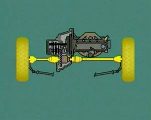
In front wheel drive vehicles, the drive shafts transfer the drive directly from the differential to the front wheels. A short inner stub shaft is splined to the differential side gear and an outer stub shaft is splined to the front wheel hub. Each stub shaft has a yoke, or housing, to accommodate a universal joint, at each end of a connecting intermediate shaft.
Universal joints let the shaft keep rotating while allowing for changes due to suspension movement - such as shaft length and horizontal angle, and shaft angle as the steering turns.
Constant-velocity universal joints are normally used to transfer power smoothly between the components.
The inner universal can be a plunge or tripod type joint. The tripod is splined to the intermediate shaft and held by a circlip. A ball, supported on needle roller bearings, is fitted to each post of the tripod, and these slide in a trunnion inside the yoke. This caters for changes in shaft length and horizontal angle.
The drive is transferred through the trunnion and balls to rotate the shaft. The outer universal joint allows greater angular changes but not changes in shaft length. It is normally a ball and cage type with an inner race splined to the intermediate shaft. An outer race is formed in the yoke. The cage retains the balls in location in grooves in both races. The balls transfer the drive from the shaft to the hub and allow for changes in horizontal angle and for a wide steering angle to be achieved.
A flexible rubber boot fitted to each joint retains grease and keeps out dirt and moisture. Where the differential is not located in the centre line of the vehicle, an intermediate shaft can be fitted to maintain equal length drive shafts on each side. This keeps drive shaft angles equal on both sides and helps prevent steering irregularities and vibration. The outer end of the intermediate shaft is supported by a bearing secured to the transaxle case and a universal joint assists with alignment. In some cases a longer drive shaft is used on one side. A rubber dynamic damper may be fitted to absorb vibrations.
When a vehicle turns, the outer wheel travels a greater distance than the inner wheel, so it turns through more revolutions. The differential allows the 2 drive shafts and the driving road wheels to rotate at different speeds when turning, while still applying an equal turning effort to both. Differential gears are bevel gears, at right angles to each other inside a case, which is supported on bearings in the final drive housing.
The ring gear is bolted to the case, so when it rotates, so does the case, and the differential gears inside it. The two smaller bevel gears, or pinions, are mounted on a driving pin which passes through the case. Two side gears mesh with the pinions and are in recesses in the differential case. The drive shafts are splined to these side gears.
When the vehicle travels in a straight line, the ring gear rotates the case. The driving pin and pinion gears rotate end over end, turning the side gears with them, and the drive shafts. There is no relative motion between the pinion gears and the side gears: each side gear turns at the same speed. As soon as the vehicle turns from a straight ahead position, the inner wheel slows down and its side gear turns more slowly than the differential case. The turning effort applied to the driving pin, forces the pinion gears to rotate slowly on the pin. They walk around the inner side gear while still being turned end over end. This rotation of the pinion gears makes the outer side gear, and its road wheel, speed up by an equivalent amount. The outer side gear then turns faster than the case. This provides an equal turning effort to each drive shaft while allowing for their speed difference.
5.3 Rear-Wheel Final Drive
In a conventional rear wheel drive, a beam axle assembly encloses the final drive gears, differential and axle shafts in one housing. A crown wheel and pinion transfers the drive through ninety degrees, and provides a final gear reduction to the driving road wheels.
Hypoid bevel gears are normally used for this purpose. Hypoid gears are a special design of spiral bevel gears, with the centre line of the pinion below the centre line of the crown wheel. This reduces the height of the propeller shaft tunnel to give a flatter floor pan. The tooth shape provides a greater area of tooth contact, and therefore greater strength. The crown wheel, pinion and differential gears are mounted in a differential carrier which can be separated from the axle housing.
Taper roller bearings support the pinion in the carrier. The companion flange splines engage with the pinion splines, to transfer the drive from the propeller shaft. A collapsible spacer, between the bearings, allows a specified pre-load to be set, and depth of mesh shims position the pinion in relation to the crown wheel.
The crown wheel is bolted to the differential case, which is supported in the carrier by taper roller bearings, retained by bearing caps and bolts. Threaded adjusting rings engage with threads in the carrier, and these are used to set the bearing pre-load and a back-lash clearance between the crown wheel and pinion. With the carrier bolted to the axle housing, the splines on the axle shafts can engage with the splines of the differential side gears, and drive is transferred through the differential case and gears, to the road wheels.
The propeller shaft transfers the drive from the transmission to the final drive. It normally has a hollow tubular construction, and in this example, yokes are welded to each end to accept universal joints. The rear joint connects to a flanged yoke designed to mate with a companion flange on the final drive pinion, while the front joint links to an internally splined slip yoke, which engages with splines on the transmission output shaft. On the outside of the slip yoke, a bearing surface supports the front end of the propeller shaft in a plain bearing, in the transmission extension housing. This enables the slip yoke to move longitudinally and vary the shaft length with suspension movement.
The most common type of universal is a Hooke's joint or a cross-and-roller joint. It consists of a steel cross with four hardened bearing journals, mounted on needle rollers in hardened caps, which locate the cross in the eyes of the yokes. The cross swivels in the yokes as the drive is transferred from one shaft to the other. However, the swiveling conflicts with the rotation and in each revolution the velocity of the yoke changes every 90 degrees. This change in the angular velocity increases as the angle between the driving and driven shafts increases. This type of joint is a non-constant velocity joint.
The effect of the changing velocity can be eliminated by having identical joints at each end of the propeller shaft in phase with each other, and by having the input and output drives parallel. An increase in the velocity of the front yoke is cancelled out by a similar decrease in the velocity of the rear yoke in each revolution. In some cases a type of constant-velocity joint is fitted to the front end of the propeller shaft. A number of balls, retained by a spherical cage, are carried in angular grooves in each race, and these balls transfer the drive from one race to the other. The outer race is also able to move longitudinally on the inner race grooves and this accommodates changes in shaft length.
This type of joint allows the drive to be transmitted through a greater angle and minimizes vibration. Where the angle between the shafts is small, a flexible hard rubber coupling can be sandwiched between tripod flanges on the propeller shaft and the differential pinion. Since no friction-producing parts are involved, noise and vibration are reduced to a minimum.
Source: http://local.ecollege.ie/Content/APPRENTICE/liu/hvm_notes/M4U2.doc
Web site to visit: http://local.ecollege.ie
Author of the text: indicated on the source document of the above text
If you are the author of the text above and you not agree to share your knowledge for teaching, research, scholarship (for fair use as indicated in the United States copyrigh low) please send us an e-mail and we will remove your text quickly. Fair use is a limitation and exception to the exclusive right granted by copyright law to the author of a creative work. In United States copyright law, fair use is a doctrine that permits limited use of copyrighted material without acquiring permission from the rights holders. Examples of fair use include commentary, search engines, criticism, news reporting, research, teaching, library archiving and scholarship. It provides for the legal, unlicensed citation or incorporation of copyrighted material in another author's work under a four-factor balancing test. (source: http://en.wikipedia.org/wiki/Fair_use)
The information of medicine and health contained in the site are of a general nature and purpose which is purely informative and for this reason may not replace in any case, the council of a doctor or a qualified entity legally to the profession.
The texts are the property of their respective authors and we thank them for giving us the opportunity to share for free to students, teachers and users of the Web their texts will used only for illustrative educational and scientific purposes only.
All the information in our site are given for nonprofit educational purposes