Mechanical Electrical Systems
Mechanical Electrical Systems
- Environmental Issues:
- Conduction
- Direct transmission of energy by a medium that does not involve movement of the medium itself.
- The basics of Thermal conductivity.
- Thermal conductivity is the quantity of heat, Q, transmitted through a thickness L, in a direction normal to a surface of area A, due to a temperature gradient ΔT, under steady state conditions and when the heat transfer is dependent only on the temperature gradient.
- Thermal conductivity = heat flow rate × distance / (area × temperature gradient)
- λ = Q × L / (A × ΔT)
- Coefficient of heat transmission (U-value)
- A value that describes the ability of a material to conduct heat. The number of Btu that flow through one square foot of material in one hour. It is the reciprocal of the R-value (i.e. U-value = 1/R-value).
- The lower the number, the greater the heat transfer resistance (insulating) characteristics of the material.
- Latent heat
- The change in heat content that occurs with a change in phase and without change in temperature.
- The basics of Wet-bulb temperature.
- Wet-bulb temperature is measured using a standard mercury-in-glass thermometer, with the thermometer bulb wrapped in muslin, which is kept wet. The evaporation of water from the thermometer has a cooling effect, so the temperature indicated by the wet bulb thermometer is less than the temperature indicated by a dry-bulb (normal, unmodified) thermometer. The rate of evaporation from the wet-bulb thermometer depends on the humidity of the air - evaporation is slower when the air is already full of water vapor. For this reason, the difference in the temperatures indicated by the two thermometers gives a measure of atmospheric humidity.
- Relative humidity
- The ratio of the amount of water vapor in the air at a specific temperature to the maximum amount that the air could hold at that temperature, expressed as a percentage.
- Hygrometer
- Instrument used to measure the moisture content of a gas, as in determining the relative humidity of air. The temperature at which dew or frost forms is a measure of the absolute humidity—the weight of water vapor per unit volume of air or other gas at the temperature before cooling. Knowing absolute humidity and air temperature, the observer can calculate relative humidity.
- Dew point
- The dew point or dewpoint of a given parcel of air is the temperature, to which the parcel must be cooled, at constant barometric pressure, for the water vapor component to condense into water, called dew. When the dew point temperature falls below freezing it is called the frost point, instead creating frost or hoar frost by deposition.
- Atmospheric pressure
- Pressure caused by the weight of the atmosphere. At sea level it has a mean value of one atmosphere but reduces with increasing altitude.
- The two basic types of active-solar heating systems.
- There are two basic types of active-solar heating systems, depending on whether air or a liquid is heated in the solar collector. A liquid-based system heats water or an antifreeze solution in a "hydronic" collector, and an air-based system heats air in an "air collector."
- Both of these systems collect and absorb solar radiation, then transfer the solar heat directly to the interior space or to a storage system, from which the heat is distributed. If the system cannot provide adequate space heating, an auxiliary or back-up system provides the additional heat. Liquid-based systems are more often used when storage is included.
- In an active-solar water heating system, heated water is moved through the system with the aid of pumps, which increases the system's efficiency.
- Flat-plate collectors
- Flat-plate collectors are the most common collector for residential water-heating and space-heating installations. A typical flat-plate collector is an insulated metal box with a glass or plastic cover (called the glazing) and a dark-colored absorber plate. These collectors heat either liquid or air at temperatures less than 180°F.
- Concentrating collectors
- Concentrating collectors use curved mirrors to concentrate sunlight on an absorber, called a receiver, at up to 60 times the sun's normal intensity. These high-temperature systems are used primarily in commercial and industrial applications.
- The basics of Parabolic-trough collectors.
- Parabolic-trough collectors use trough-shaped reflectors that concentrate sunlight on a tube running along the reflector's focal line, achieving much higher temperatures than flat-plate or evacuated-tube collectors. These systems usually include a mechanical control system, called a tracker that keeps the trough reflector pointed at the sun throughout the day. Parabolic-trough concentrating systems can provide hot water and steam, and are generally used in commercial and industrial applications.
- Oil/water separators.
- Oil/water separators are mechanical wastewater treatment devices that remove oily and greasy contaminants from process or storm water runoff.
- The separator treats process wastewater not a result of storm water and discharges to the environment.
- Plumbing:
- The basics of upfeed and downfeed distribution.
- Small buildings may be served by pressure available in water mains or pressure tanks fed by pumped wells. This approach is called upfeed distribution– Water rises directly from mains to plumbing fixtures
- Taller buildings- other options– pumped upfeed- pumps supply the additional needed pressure– Hydropneumatic- pumps force water into sealed tanks, compressing the air within and providing the needed pressure– Downfeed systems- pumps raise water to storage on top of building, water drops down to fixtures.
- Separate floors into zones to control water pressure. Usual limit is 150 ft due to the to static pressure relationship.– Top of zone (35 ft below storage) min psi 35 is achieved- at bottom of zone 80psi occurs and pressures above this can damage pipes and fixtures– Pressure reducing valves at lower floors can help reduce this.
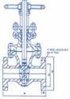
- Gate Valve
- The gate valve is a general service valve used primarily for on--off, non-throttling service. The valve is closed by a flat face, vertical disc, or gate that slides down through the valve to block the flow.
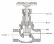
- Globe Valve
- The globe valve effects closure by a plug with a flat or convex bottom lowered onto a matching horizontal seat located in the center of the valve. Raising the plug opens the valve, allowing fluid flow. The globe valve is used for on--off service and handles throttling applications.
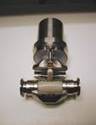
- Pinch Valve
- The pinch valve is particularly suited for applications of slurries or liquids with large amounts of suspended solids. It seals by means of one or more flexible elements, such as a rubber tube, that can be pinched to shut off flow.
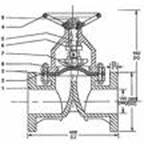
- Diaphragm Valve
- The diaphragm valve closes by means of a flexible diaphragm attached to a compressor.
- When the compressor is lowered by the valve stem onto a weir, the diaphragm seals and cuts off flow. The diaphragm valve handles corrosive, erosive and dirty services.
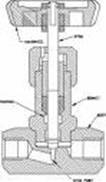
- Needle Valve
- The needles valve is a volume-control valve that restricts flow in small lines. The fluid going through the valve turns 90 degrees and passes through an orifice that is the seat for a rod with a cone-shaped tip. The Size of the orifice is changes by positioning the cone in relation to the seat.
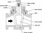
- Plug Valve
- The plug valve is used primarily for on-off service and some throttling services. It controls flow by means of a cylindrical or tapered plug with a hole in the center that lines up with the flow path of the valve to permit flow. A quarter turn in either direction blocks the flow path.
- Ball Valve
- The ball valve is similar in concept to the plug valve but uses a rotating ball with a hole through it that allows straight-through flow in the open position and shuts off flow when the ball is rotated 90 degrees to block the flow passage. It is used for on--off and throttling services.
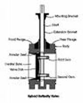
- Butterfly Valve
- The butterfly valve controls flow by using a circular disc or vane with its pivot axis at right angles to the direction of flow in the pipe. The butterfly valve is used both for on--off and throttling services.
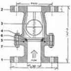
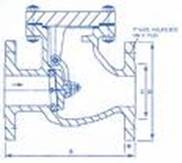
- Check Valve
- The check valve is designed to prevent backflow. Fluid flow in the desired direction opens the valve, while backflow forces the valve closed.
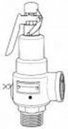
- Pressure Relief Valve
- The pressure relief valve is designed to provide protection from over-pressure in steam, gas, air and liquid lines. The valve "lets off steam" when safe pressures are exceeded, then closed again when pressure drops to a preset level.
- The basics of Tankless hot water heaters.
- Tankless hot water heaters save energy. Water heating accounts for 20% or more of an average household’s annual energy expenditures. The yearly operating costs for conventional gas or electric storage tank water heaters average $200 or $450, respectively.
- Storage tank-type water heaters raise and maintain the water temperature to the temperature setting on the tank (usually between 120° -140° F (49° -60° C). Even if no hot water is drawn from the tank (and cold water enters the tank), the heater will operate periodically to maintain the water temperature.
- Tankless hot water heaters have a heating device that is activated by the flow of water when a hot water valve is opened. Once activated, the heater delivers a constant supply of hot water. The output, however, limits the rate of the heated water flow.
- Soil Stack
- Largest vertical drain line to which all branch waste lines connect; carries waste to the sewer line.
- Trap
- Curved section of a fixture drain line, designed to hold water thus preventing sewer gases from entering the house.
- Fall/Flow
- The proper slope or pitch of a pipe for adequate drainage.
- DWV
- Abbreviation for drain, waste and vent.
- Closet Bend
- A curved fitting that connects the closet flange to the toilet drain.
- ABS (Acrylonitrile butadiene styrene)
- Rigid black plastic pipe used only for drain lines.
- Riser
- A vertical assembly of fittings and pipes that distributes water upward.
- Union
- Three-piece fitting that joins two sections of pipe, but allows them to be disconnected without cutting the pipe. Used primarily with steel pipes, but never in a DWV system.
- The basics of a Leach Field.
- Liquid drains from the relatively clear portion of the tank to the leach field (also referred to as a drain field, or seepage field, depending upon locality) where the remaining impurities naturally decompose and the water is eliminated through percolation into the soil, and eventually taken up through the root system of plants or added to the groundwater.
- The basics of Polyvinyl chloride (PVC).
- A widely-used plastic. In terms of revenue generated, it is one of the most valuable products of the chemical industry. Globally, over 50% of PVC manufactured is used in construction. As a building material PVC is cheap, and easy to assemble. In recent years, PVC has been replacing traditional building materials such as wood, concrete and clay in many areas. UV light causes deterioration of PVC. Despite appearing to be an ideal building material, concerns have been raised about the environmental and human health costs of PVC.
- HVAC:
- HVAC Systems
- Heating, ventilating and air-conditioning (HVAC) systems can play several roles to reduce the environmental impact of buildings. The primary function of HVAC systems is to provide healthy and comfortable interior conditions for occupants; well-designed, efficient systems do this with minimal non-renewable energy and air and water pollutant emissions. Cooling equipment that avoids chlorofluorocarbons and hydrochlorofluorocarbons (CFCs and HCFCs) eliminates a major cause of damage to the ozone layer.
- However, even the best HVAC equipment and systems cannot compensate for a building design with inherently high cooling and heating needs. The greatest opportunities to conserve non-renewable energy are through architectural design that controls solar gain, while taking advantage of passive heating, daylighting, natural ventilation and cooling opportunities. The critical factors in mechanical systems’ energy consumption – and capital cost – are reducing the cooling and heating loads they must handle.
- The basics of a Fan coil system.
- Fan coil system is an air conditioning system used in buildings. A fan unit is placed at each place which needs to be heated or cooled. A central plant delivers hot or cold water to fan units.
- The fan draws air from the room, blows it over the water coil and returns it to the room.
- Dehumidified air from a central plant or fresh air from outside may also be used by a fan coil system.
- The basics of an air handling unit.
- Air Handling Unit – AHU: Term used to define a ventilation system consisting of the following major components (some being enclosed within an enclosure or casing): air intakes, filters, fans, electric heating coils, connected ductwork and components, fire and control dampers, electric reheat boxes, air diffusion equipment, electrical connections, power supplies, distribution boards and control systems. The AHU ventilation system may or may not include the following additional items: direct expansion or chilled water cooling coil, refrigerant storage and pump systems and packaged air cooled refrigerant condensers or connections to a separate chilled water supply system, and electric steam humidifiers.
- The Benefits of a Heat Pump System.
- Because a heat pump does not burn fuel, it is safer and cleaner to run than a gas powered furnace.
- A heat pump provides a more uniform temperature throughout a building. It does not produce a sudden blast of hot air as traditional furnaces do each time they kick on.
- In the heat mode, heat pumps do not dry out the air the way traditional heaters do. The higher humidity maintained by heat pumps during cold weather provides for a healthier environment.
- Heat pumps are more efficient and cost less to run than electric furnaces.
- Because heat pumps are used year round (for cooling as well as heating needs), they cost less per hour of use (cost of purchase and installation divided by total number of hours used per year) than do individual heating and cooling systems, which each sit idle for a good part of the year.
- The basics of Heat pump water heater (HPWH) systems.
- Heat pump water heater (HPWH) systems mine the energy content of air to produce hot water very efficiently. Depending on cold-water and ambient-air temperatures and on patterns of hot water use, heat pump water heaters do the same job as standard electric water heaters using two to three times less electric energy.
- Heat pump water heaters use a motor to run a compressor. The compressor draws a gaseous refrigerant through an evaporator, raising its pressure until it liquefies in the condenser. This familiar process heats the condenser and cools the evaporator. In wringing the heat from air, HPWHs both cool and dehumidify the air that passes through them, thus helping to meet space conditioning needs during cooling seasons. Under most scenarios, the extra costs of heat pump water heaters over standard electric water heaters are paid back in two to three years.
- HPWH systems are available in a variety of capacities, from small residential to large commercial, producing more than 350 gallons per hour of hot water and 6 tons of air conditioning. Options to consider include system configurations and efficiencies.
- The basics of Unitary heat pumps.
- Unitary heat pumps are factory-packaged refrigerant-based heat pumps that are available in a number of application categories which include:
- Packaged terminal heat pumps (PTHP)
- Closed water loop heat pump systems
- Ground-Coupled (Closed-Loop) Systems
- Ground water-source heat pumps
- Large unitary air- and water-source heat pumps
- With the exception of large unitary heat pumps, the units are designed for free-air delivery or with short duct connections between the unit and the conditioned space. Most heat pump manufacturers participate in the Air-Conditioning and Refrigeration Institute (ARI) Certification Program.
- They provide individual temperature control in small occupied zones during nights and weekends without the need for a large central plant chiller or boiler and their associated pumps.
- The heat pump's consumption of electricity can be separately metered.
- The three types of insulation materials are commonly used to insulate ducts.
- Fiberglass building insulation
- Vinyl-backed fiberglass metal building insulation (similar to water heater insulation)
- Foil scrim kraft (FSK) duct insulation
- Duct insulation is typically secured with polyethylene twine or rust-free wire.
- The basics of the ASHRAE.
- American Society of Heating, Refrigerating and Air-Conditioning Engineers, Inc.
- Mission Statement
- ASHRAE will advance the arts and sciences of heating, ventilation, air conditioning, refrigeration and related human factors to serve the evolving needs of the public and ASHRAE members.
- Electrical:
- Busbar (bus)
- A low impedance conductor to which several circuits/conductors can be separately connected.
- Circuit-breaker
- A switching device, capable of making, carrying and breaking currents under normal circuit conditions and also making, carrying for a specified time and breaking currents under specified abnormal conditions such as those of short circuit.
- Circuit-breaker control selector switch
- A control switch provided within each circuit-breaker operating mechanism cabinet to enable the circuit-breaker to be closed and opened at the circuit-breaker during maintenance and test work, and sometimes to completely disable the circuit-breaker.
- Circuit-breaker disconnector
- The functional term for a disconnector that provides a point-of-isolation for a circuit-breaker.
- Circuit-breaker lockout
- The status of a circuit-breaker deliberately prevented from operating due to the action of a monitoring or protection device.
- The basics of Insulators.
- Insulators are materials which prevent the flow of heat (thermal insulators) or electric charge (electrical insulators). The opposite of electrical insulators are conductors and semiconductors, which permit the flow of charge (Note: a semiconductor is strictly speaking also an insulator, since it prevents the flow of electric charge at low temperatures, unless it is doped with atoms that release extra charges to carry the current). The term electrical insulator has the same meaning as the term dielectric, but the two terms are used in different contexts.
- A perfect insulator is impossible to achieve due to the second law of thermodynamics. However, some materials (such as silicon dioxide) are very nearly perfect electrical insulators, which allow flash memory technology.
- The basics of Ohm's law.
- The law stating that the direct current flowing in a conductor is directly proportional to the potential difference between its ends.
- It is usually formulated as V = IR, where V is the potential difference, or voltage, I is the current, and R is the resistance of the conductor.
- V or E = voltage (E=energy)
- I = current in amps (I=intensity)
- R = resistance in ohms
- P = power in watts
- V = I * R
- E = I * R
- I = V / R
- I = E / R
- R = V / I
- R = E / I
- P = V * I
- P = E * I
- The basics of Resistors.
- An ideal resistor is a component with an electrical resistance that remains constant regardless of the applied voltage or current flowing through the device or the rate of change of the current.
- Resistors may be fixed or variable. Variable resistors are also called potentiometers or rheostats and allow the resistance of the device to be altered by turning a shaft or sliding a control.
- Some resistors are long and thin, with the actual resisting material in the centre, and a conducting metal leg on each end. This is called an axial package. Resistors used in computers and other devices are typically much smaller, often in surface-mount (Surface mount technology) packages without leads. Larger power resistors come in more sturdy packages designed to dissipate heat efficiently, but they are all basically the same structure.
- Resistors are used as part of electrical networks and incorporated into microelectronic semiconductor devices. The critical measurement of a resistor is its resistance, which serves as a ratio of voltage to current and is measured in ohms, an SI unit. A component has a resistance of 1 ohm if a voltage of 1 volt across the component results in a current of 1 ampere, or amp, which is equivalent to a flow of one coulomb of electrical charge (approximately 6.241506 × 10¹⁸ electrons) per second in the opposite direction.
- Lighting:
- The benefits of Fluorescents.
- Fluorescents are not only one of the most efficient options around, offering the longest-life bulb; they come in a variety of colors, types and sizes. Best of all, with the new electronic ballasts, they are quiet. Fluorescent lights are phosphor-coated glass tubes filled with an inert gas and a small amount of mercury. Because different brands can have different mixes of gases inside, fluorescents produce a wide assortment of color light that match the warm glow of incandescent.
- All fluorescent lights need a controlling ballast to operate. The ballast alters the electric current flowing through the fluorescent tube, activating the gas inside and causing it to glow. Newly developed electronic ballasts eliminate that annoying flicker and buzz that used to occur with old magnetic ballasts, which were also heavier and less efficient.
- To create the same amount of light as an incandescent bulb, a fluorescent tube uses only one-quarter to one-third of the energy. Plus, fluorescents last 10 to 15 times longer - 10,000 hours or more.
- Foot candle
- A unit of measure of the intensity of light falling on a surface, equal to one lumen per square foot and originally defined with reference to a standardized candle burning at one foot from a given surface.
- Candela
- A unit of measurement of the intensity of light. Part of the SI system of measurement, one candela (cd) is the monochromatic radiation of 540THz with a radiant intensity of 1/683 watt per steradian in the same direction. Another way of putting it is that an ordinary wax candle generates approximately one candela.
- Lumen
- A unit of measurement of the amount of brightness that comes from a light source. The standard lumen rating of a data projector is the average of photometer readings at several points on a full white image on the screen.
- Technically, lumens measure "luminous flux." A wax candle generates 13 lumens; a 100 watt bulb generates 1,200. The lumen rating is a critical specification when choosing a data projector. In a darkened room, 500 lumens may be ample; however, in a conference room with normal lighting, 1,000 lumens would be better. In a room with bright daylight, 2,000 lumens is preferred.
- "Ambient" lighting provides a minimum amount of illumination for people to see each other and move about,
- "General lighting" provides enough illumination for reading or viewing objects,
- "Task lighting" provides bright enough light for close work and viewing detail.
- Indirect Lighting: Lighting by luminaires that distribute 90 to 100% of the emitted light upward.
- Indirect Glare: Glare produced from a reflective surface.
- Equivalent Sphere Illumination (ESI): The amount of light in foot-candles produced by a luminous sphere on a seeing task in the center of the sphere that will render the same "see ability" as the raw foot-candles render the same task in the specific seeing environment under consideration.
- Incandescent Filament Lamp: a lamp in which light is produced by a filament heated to incandescence by an electric current.
- Baffle: A shield of metal, wood or plastic used to screen a light source from normal angles of viewing. Aluminum baffles are commonly used in parabolic fixtures or, a grooved cylinder dropped below a light source to conceal the lamp and provide light cutoff.
- Ballast: A device used in fluorescent and HID luminaires to provide the necessary starting voltage and to limit the lamp current during operation.
- Ballast (Cold Weather): Ballast designed to provide sufficient starting voltage for fluorescent lamps in cold weather, generally down to 0 degrees F.
- Ballast (Dimming): Dimming ballasts are special ballasts which, when used together with a dimmer control, will vary the light output of a lamp.
- Specialties: Acoustics: Evaluate, select, and design acoustical systems.
- The basics of Decibels.
- The sound intensity I may be expressed in decibels above the standard threshold of hearing I0. The expression is
- I (dB) = 10 log10 [ I / Io ] intensity of decibel
- Decibels provide a relative measure of sound intensity. The unit is based on powers of 10 to give a manageable range of numbers to encompass the wide range of the human hearing response, from the standard threshold of hearing at 1000 Hz to the threshold of pain at some ten trillion times that intensity.
- What is a Decibel?
- A nonlinear (logarithmic) measure called the decibel is used to quantify sounds over this extensive range of pressures. Different definitions of the decibel (dB) are used for sounds in air versus sounds in water. The SOUND PRESSURE LEVEL in decibels is defined as 20 log (pressure/reference pressure), using base 10 logarithms. Usually the pressure referred to here is the "root mean square" average pressure (abbreviated as rms). The loudness or intensity of a sound is proportional to the square of the rms average pressure that the molecules exert on their neighbors as the wave propagates. Hence, the loudness of a sound in decibels can also be defined as 10 log (intensity/reference intensity). The reference pressure for sound waves in water is taken to be 1 microPascal while in air, the reference pressure used is 20 microPascals.
- The basics of Sound transmission class (STC).
- A system devised by the ASTM in 1961 to describe how well various types of interior walls, floors, doors, etc. prevent sound in one room from reaching another.
- To assign an STC rating to a barrier separating two rooms, a sound is generated in one of the rooms, the sound power is measured on both sides of the barrier, and the ratio between the two measurements (the transmission loss) is stated in decibels. Sixteen measurements are made in each room, at 1/3 octave intervals from 125 Hz to 4000 Hz.
- The STC system is useful for comparing different ways of building a partition, but it is not a guarantee of a certain level of isolation. It tends to give too much credit to materials which absorb high frequencies, such as sheetrock, and too little to materials and forms of construction which absorb the lower frequencies.
- Sabin
- A unit of acoustic absorption equivalent to the absorption by one square foot of a surface that absorbs all incident sound.
- The Doppler Effect.
- The Doppler Effect is the apparent change in frequency or wavelength of a wave that is perceived by an observer moving relative to the source of the waves.
- For waves, such as sound waves, that propagate in a wave medium, the velocity of the observer and the source are reckoned relative to the medium in which the waves are transmitted.
- It is important to note that the effect does not result because of an actual change in the frequency of the source.
- The following terms:
- Reflection involves a change in direction of waves when they bounce off a barrier.
- Refraction of waves involves a change in the direction of waves as they pass from one medium to another. Refraction, or bending of the path of the waves, is accompanied by a change in speed and wavelength of the waves.
- Diffraction involves a change in direction of waves as they pass through an opening or around a barrier in their path.
- Specialties: Conveying Systems: Evaluate, select, and design elevators, escalators, moving walkways, and other conveying systems.
- Alternating Current: AC is the standard form of electrical current supplied by the utility grid and by most fuel-powered generators. The polarity (and therefore the direction of current) alternates.
- Direct Current (dc): electric current flowing in one direction. Often used for elevators.
- The contributions of Werner von Siemens.
- In 1866 Werner von Siemens made what his most important contribution was probably to electrical engineering with his discovery of the dynamoelectric principle, thus paving the way for the use of electricity as a source of energy. In 1888 he was raised to the nobility by Emperor Friedrich III in acknowledgement of his services to science and society.
- Built first electric elevator - 1880.
- The contributions of Elisha Graves Otis. 1811-1861
- Invention: Elisha invented the break for the elevator using a tough, steel wagon spring meshing with a ratchet.
- When there was tension on the rope holding the elevator, tough jagged metal teeth on the sides of the elevator shaft grabbed elevator car holding it in place. Elisha was working in a factory in New York when he decided to make a break for the hoist that was used to take heavy objects up to other floors. Elisha gave his first performance of his elevator break at a city fair. His invention affected the whole world because it made the elevator much safer.
- Specialties: Fire Detection & Suppression: Evaluate, select, and design fire detection and suppression systems.
- The 4 Stages of a Fire.
- I - During the first, incipient stage, which may last for seconds to days, there is no noticeable smoke, heat or flame. During this stage, flammable gasses, or “products of combustion” are emitted
- II - Next, is the smoldering stage, during which there still is no substantial flame or heat, but the combustion increases enough to create visible smoke.
- III - The flame stage usually involves less smoke, but flames break out generating substantial heat.
- IV - The fourth stage of a fire is often referred to as the high heat stage. At this point, the fire has spread rapidly throughout the home, producing extensive flames, extreme heat and many toxic gases.
- A Flame Detector.
- A flame detector responds either to radiant energy visible to the human eye (approx. 4000 to 7700 A) or outside the range of human vision. Similar to the human eye, flame detectors have a 'cone of vision', or viewing angle, that defines the effective detection capability of the detector.
- With this constraint, the sensitivity increases as the angle of incidence decreases. Such a detector is sensitive to glowing embers, coals, or flames which radiate energy of sufficient intensity and spectral quality to actuate the alarm. Each type of fuel, when burning, produces a flame with specific radiation characteristics. A flame detection system must be chosen for the type of fire that is probable. For example an ultraviolet (UV) detector will respond to a hydrogen fire, but an infrared (IR) detector operating in the 4.4 micron sensitivity range will not.
- The basics of FEXT and FSPR.
- FEXT
- Term used in this standard to define portable and fixed, hand operated fire fighting equipment for use in buildings. The term not only includes water, carbon dioxide, and foam and dry powder fire extinguishers but fire hose reels, internal fire hydrants, fire service hose and nozzles.
- FSPR
- Term used to define a spray or sprinkler system connected to a water supply and includes all system types such as sprinklers, pre-action sprinklers, spray systems, drench systems and deluge systems, including all water supply pumps both diesel and electric and water supply tanks and piped water supplies from connection point to the site water supply. The system includes alarm signaling equipment for both remote and local alarms.
- The basics of FALM.
- Term which defines a building fire alarm system indicator panel and includes the components and systems connected to the indicator panel, being heat, smoke and flame detectors, very early smoke detection apparatus (VESDA), manual call points, sounders, bells, alarm lights, mimic and subsidiary panels and alarm signaling equipment for both remote and local alarms.
- The components of a dry-pipe system.
- In the dry-pipe system, a valve installed to maintain air pressure in the system is given a mechanical advantage to hold back a higher water supply pressure. This mechanical advantage is usually on the order of 6 to 1, so the air pressure recommended in the system is usually one-sixth the highest expected water supply pressure, plus a buffer of 15 psi (1 bar). As soon as a sprinkler opens, the air pressure drops. When it drops below the point at which the remaining air pressure can't hold back the water, the dry valve "trips," allowing water to enter the piping and flow to the open sprinkler. The time for water to move from the dry-pipe valve to the open sprinkler is the water transit time.
- The basics of Photoelectric Smoke Detectors.
- Occasionally, you will walk into a store and a bell will go off as you cross the threshold. If you look, you will often notice that a photo beam detector is being used. Near the door on one side of the store is a light (either a white light and a lens or a low-power laser), and on the other side is a photo detector that can "see" the light.
- When you cross the beam of light, you block it. The photo detector senses the lack of light and triggers a bell. You can imagine how this same type of sensor could act as a smoke detector. If it ever got smoky enough in the store to block the light beam sufficiently, the bell would go off. But there are two problems here:
- It's a pretty big smoke detector. It is not very sensitive. There would have to be a LOT of smoke before the alarm would go off -- the smoke would have to be thick enough to completely block out the light. It takes quite a bit of smoke to do that.
- Photoelectric smoke detectors therefore use light in a different way. Inside the smoke detector there is a light and a sensor, but they are positioned at 90-degree angles to one another.
- The basics of Ionization Smoke Detectors.
- Ionization Detectors: Ionizing Radiation
- Ionization smoke detectors use an ionization chamber and a source of ionizing radiation to detect smoke. This type of smoke detector is more common because it is inexpensive and better at detecting the smaller amounts of smoke produced by flaming fires.
- Inside ionization detector is a small amount (perhaps 1/5000th of a gram) of americium-241.
- The radioactive element americium has a half-life of 432 years, and is a good source of alpha particles.
- HISTORY IN MEP
- Roman aqueduct
- Corbusier’s Notre Dame at Ron champ - Lighting
- the Pantheon in Rome - Lighting
- The fan window from Gothic architecture
- Thermal mass and ventilation in one of Palladio's Villas.
- Acoustical problem found in a Greek theater?
Source: http://www.areforum.org/up/Mechanical%20and%20Electrical/Mechanical%20and%20Electrical.doc
Web site to visit: http://www.areforum.org/
Author of the text: indicated on the source document of the above text
If you are the author of the text above and you not agree to share your knowledge for teaching, research, scholarship (for fair use as indicated in the United States copyrigh low) please send us an e-mail and we will remove your text quickly.
Fair use is a limitation and exception to the exclusive right granted by copyright law to the author of a creative work. In United States copyright law, fair use is a doctrine that permits limited use of copyrighted material without acquiring permission from the rights holders. Examples of fair use include commentary, search engines, criticism, news reporting, research, teaching, library archiving and scholarship. It provides for the legal, unlicensed citation or incorporation of copyrighted material in another author's work under a four-factor balancing test. (source: http://en.wikipedia.org/wiki/Fair_use)
The information of medicine and health contained in the site are of a general nature and purpose which is purely informative and for this reason may not replace in any case, the council of a doctor or a qualified entity legally to the profession.
Mechanical Electrical Systems
The texts are the property of their respective authors and we thank them for giving us the opportunity to share for free to students, teachers and users of the Web their texts will used only for illustrative educational and scientific purposes only.
All the information in our site are given for nonprofit educational purposes
Mechanical Electrical Systems
