In engineering, various methods are used to represent objects. Among these, the engineering drawing or multiview drawing is a major means of communicating the design concept. In this method, orthogonal projection is used to draw and define an object.
Orthographic Projection
Pictorial drawings provide a three dimensional view of an object as it would appear to the observer. Generally, multiview and pictorial drawings are used together to provide a complete picture of the object being represented.
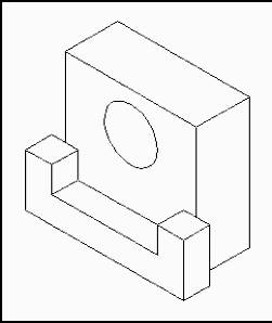
Pictorial Drawing
Projecting Views
Orthographic projection is the system of representing objects by using more than one view to define the object. There are actually 4 methods of orthographic representation. In this course you will be studying and using the Third-Angle Projection method of representation. Third-Angle Projection is the most widely used method today.
The Third-Angle projection method is an orthographic representation in which the object to be represented and seen by the viewer appears behind the coordinate viewing planes on which the object is orthographically projected.
An easier way to think of this method of projection is to imagine viewing the object and its various views through a glass box. In fact, third-angle projection is sometimes referred to as the glass-box method.
Each face of the box represents one of
the six different planes of projection
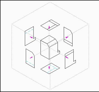
Third Angle (glass-box) Viewing Planes
Using this method, each view is projected onto its respective viewing plane. Each viewing plane is referred to as a plane of projection. The six principal planes of projection are: front, top, bottom, left side, right side, and back. In determining how the particular view will look (on the plane of projection), imagine yourself looking at the object through each side of the glass box.
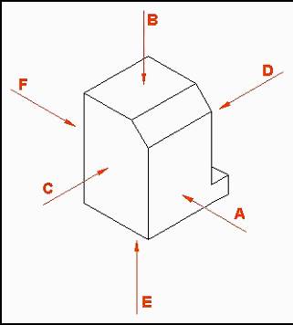
Object with Viewing Directions Indicated
View in Direction |
View From |
A |
Front |
B |
Top |
C |
Left |
D |
Right |
E |
Bottom |
F |
Back |
Generally not all of these projections are used in drawings. In determining the number of projections to use, the rule of thumb is include only as many views that are needed to represent the object accurately.
When laying out your various views on your drawing, start with the Principal View. The principal view is the view that shows the most about the product. It is usually the longest view and shows the major shape or profile. Sometimes it may be difficult to determine which view should be used as the principal view. In situations such as this, use your own discretion. This principal view is then designated as the Front View.
After your front view is selected, imagine folding out each flap of the box towards the front view.
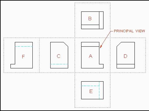
All 6 Orthographic Views Positioned Correctly on Drawing Surface
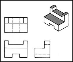
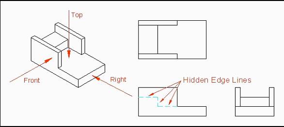
Hidden Surfaces & Edges
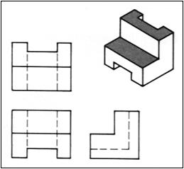
Many objects drawn in engineering contain many features (lines, holes, etc.) that cannot be seen when the object is viewed from a particular angle. These hidden details are normally required on the drawing to show the true shape of the object. Hidden lines are used to illustrate hidden detail.
Hidden lines consist of short, evenly spaced dashes. In CAD, hidden lines are given a different color and are generally assigned to a separate layer.
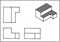
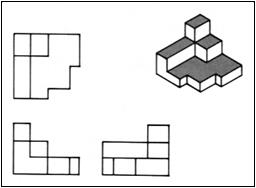
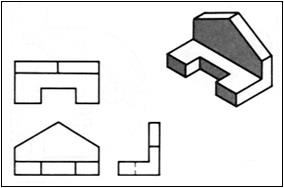
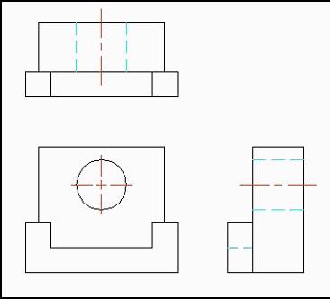
Sample Projections
Examples of orthographic projection |
|
|
|
|
|
|
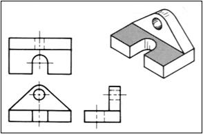
Examples of objects having hidden features |
|
|
|
|
|
|
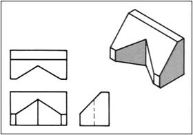
Examples of objects having sloping surfaces |
|
|
|
|
|
|
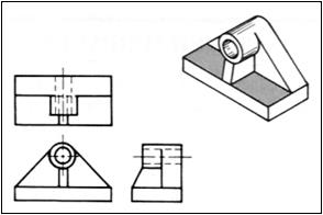
Examples of objects having circular features |
|
|
|
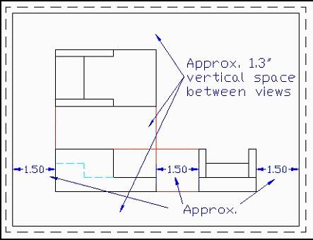
View Spacing &Alignment
For clarity and good appearance, the views should be well balanced on the drawing surface. In determining the alignment and spacing between views, the drafter must consider the size of the object to be drawn, the number of views, the scale of the printed drawing, and the space between views.
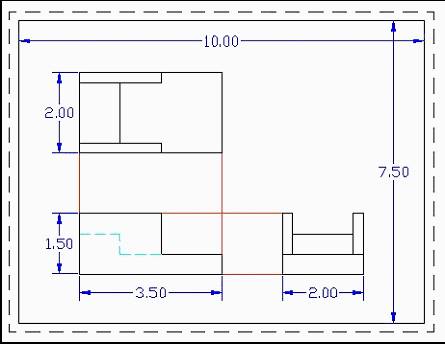
When determining the space between drawings, the drafter also needs to allow for the placement of dimensions (to be covered in a later unit).
When laying out your views, view alignment is a must. Actually, view alignment is a natural by-product of proper drafting technique (to be demonstrated in the first guided activity in this unit).
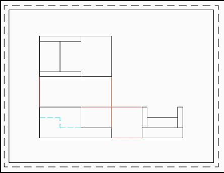
Notice that each view is perfectly aligned with the principal view (Front View).
Spacing, though important, need not be precise but should look balanced. Indicated below is one technique you may find helpful in spacing your views.
e.g. Consider the following drawing.
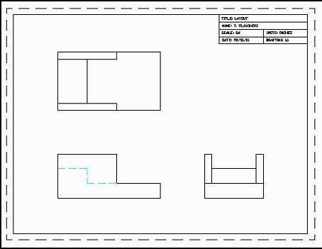
Title Block Placement
When creating engineering drawings, the drafter needs to consider title block placement as well. Title blocks are acceptable in any corner of the drawing. When considering their placement, take into account corners of the drawing that are not heavily utilized (to avoid over crowding).
Source: http://crpengineering.wikispaces.com/file/view/Mulitview%20Drawing%20Notes.doc/601134454/Mulitview%20Drawing%20Notes.doc
Web site to visit: http://crpengineering.wikispaces.com
Author of the text: indicated on the source document of the above text
If you are the author of the text above and you not agree to share your knowledge for teaching, research, scholarship (for fair use as indicated in the United States copyrigh low) please send us an e-mail and we will remove your text quickly. Fair use is a limitation and exception to the exclusive right granted by copyright law to the author of a creative work. In United States copyright law, fair use is a doctrine that permits limited use of copyrighted material without acquiring permission from the rights holders. Examples of fair use include commentary, search engines, criticism, news reporting, research, teaching, library archiving and scholarship. It provides for the legal, unlicensed citation or incorporation of copyrighted material in another author's work under a four-factor balancing test. (source: http://en.wikipedia.org/wiki/Fair_use)
The information of medicine and health contained in the site are of a general nature and purpose which is purely informative and for this reason may not replace in any case, the council of a doctor or a qualified entity legally to the profession.
The texts are the property of their respective authors and we thank them for giving us the opportunity to share for free to students, teachers and users of the Web their texts will used only for illustrative educational and scientific purposes only.
All the information in our site are given for nonprofit educational purposes