
PROPAGATION OF LIGHT IN AN OPTICAL FIBER (RAY MODEL)
1.1 BASICS
1. Optical fiber is basically a solid glass rod. The diameter of rod is so small that it looks
like a fiber.
2. Optical fiber is a dielectric waveguide. The light travels like an electromagnetic wave inside the waveguide. The dielectric waveguide is different from a metallic waveguide which is used at microwave and millimeter wave frequencies.
3. In a metallic waveguide, there is a complete shielding of electromagnetic radiation but in an optical fiber the electromagnetic radiation is not just confined inside the fiber but also extends outside the fiber.
4. The light gets guided inside the structure, through the basic phenomenon of total internal reflection.
5. The optical fiber consists of two concentric cylinders; the inside solid cylinder is called the core and the surrounding shell is called the cladding. (See Fig 1)
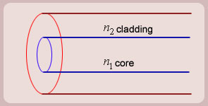
Figure1 Schematic of an optical fiber
6. For the light to propagate inside the fiber through total internal reflections at
core-cladding interface, the refractive index of the core must be greater than the refractive
index of the cladding. That is ![]() .
.
1.2 SIMPLE RAY MODEL
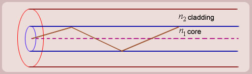
Figure 2 (optical fiber with core, cladding and total internally reflected ray)
For propagation of light inside the core there are two possibilities.
1. A light ray is launched in a plane containing the axis of the fiber. We can then see the light ray after total internal reflection travels in the same plane i.e., the ray is confined to the plane in which it was launched and never leave the plane. In this situation the rays will always cross the axis of the fiber. These are called the Meridional rays. (Fig. 2)
2. The other possibility is that the ray is not launched in a plane containing the axis of the fiber.
For example if the ray is launched at some angle such that it does not intersect the axis of the fiber, then after total internal reflection it will go to some other plane. We can see that in this situation the ray will never intersect the axis of the fiber. The ray essentially will spiral around the axis of fiber. These rays are called the Skew rays.
So it can be concluded that if the light is to propagate inside an optical fiber it could be through two types of rays
a) Meridional rays: The rays which always pass through the axis of fiber giving high optical intensity at the center of the core of the fiber.
b) Skew Rays: The rays which never intersect the axis of the fiber, giving low optical intensity at the center and high intensity towards the rim of the fiber.
1.3 Propagation of Meridional Rays

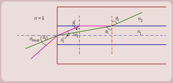
Figure (3)
The question is, under what conditions the ray is ultimately guided inside the core due to total internal reflections at the core cladding boundary?
If ![]() < critical angle the ray is refracted in cladding. The ray which goes to cladding is lost and is not useful for communication. The ray which is confined to the core is useful for optical communication.
< critical angle the ray is refracted in cladding. The ray which goes to cladding is lost and is not useful for communication. The ray which is confined to the core is useful for optical communication.
3. Now as we increase the launching angle ![]() , the angle
, the angle ![]() also increases.
also increases.
Since
![]() ,
,
![]() decreases and at some point becomes less than the critical angle. When
decreases and at some point becomes less than the critical angle. When ![]() equals the critical angle,
equals the critical angle, ![]() equals
equals ![]() . The maximum launching angle then corresponds to
. The maximum launching angle then corresponds to ![]() .
.
we then have
![]() (since
(since ![]() )
)
![]()
![]()
now,
So the sine of the maximum angle at which the ray will be guided inside the fiber is given by square root of the difference of squares of the refractive indices of the core and cladding. The quantity![]() is called the NUMERICAL APERTURE of an optical fiber. The NA is a measure of the power launching efficiently of an optical fiber.
is called the NUMERICAL APERTURE of an optical fiber. The NA is a measure of the power launching efficiently of an optical fiber.
5. Numerical Aperture: This parameter tells us that if we take an optical fiber and put it in front of an optical source then how much light is collected by the fiber from the source. Smaller the value of N.A, smaller the value of ![]() (maximum launching angle) and smaller is the power accepted by the fiber. In other words, if the light is available from various directions from the source, only a portion of light is accepted by an optical fiber and the remaining part of the light is rejected by it.
(maximum launching angle) and smaller is the power accepted by the fiber. In other words, if the light is available from various directions from the source, only a portion of light is accepted by an optical fiber and the remaining part of the light is rejected by it.
6. If we want good light launching efficiency then ![]() should be as large as possible. Since
should be as large as possible. Since ![]() is related to the difference of the squares of the refractive indices of the core and the cladding, the difference of squares of the refractive indices should be as large as possible.
is related to the difference of the squares of the refractive indices of the core and the cladding, the difference of squares of the refractive indices should be as large as possible.
So, for good launching efficiency, ![]() should be large compared to
should be large compared to![]() . Since the material for the optical fiber has been chosen as glass, the refractive index of the core is practically fixed to about 1.5.
. Since the material for the optical fiber has been chosen as glass, the refractive index of the core is practically fixed to about 1.5.
The only choice therefore we have is to reduce the refractive index of the cladding for good launching efficiency. Since ![]() (i.e., no cladding) is the minimum possible value, it suggests that the cladding is an undesirable feature. In the first look it then appears that the cladding is only for mechanical support.
(i.e., no cladding) is the minimum possible value, it suggests that the cladding is an undesirable feature. In the first look it then appears that the cladding is only for mechanical support.
4. DISPERSION
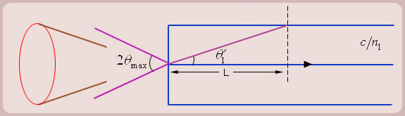
Figure (4)
2. (a) As we see from the figure 4, all the rays contained within the cone ![]() are accepted by the optical fiber.
are accepted by the optical fiber.
(b) Let us take two extreme rays; one at the lowest possible angle (along the axis of the fiber), and one at the highest possible angle (![]() ). Take a length L along the fiber axis traveled by the rays.
). Take a length L along the fiber axis traveled by the rays.
(c) Let us now transmit a narrow pulse of light. The light pulse indicates binary information. If there is a pulse then a bit is present, otherwise the bit is absent. When the light is switched on, all the rays are switched on at the same time. The pulse energy is therefore divided between different rays which travel by different paths inside the fiber.
(d) The pulse along the axis of the optical fiber takes less time to travel the distance L, than the pulse which travels at the extreme angle![]() .
.
(e) As shown in the figure 4, the distance traveled by the extreme ray is ![]() .
.
The time difference between the axial ray and the extreme ray then is:
where c is velocity of light. Since the core material is glass, ![]() , and since
, and since ![]() , it can lie between 1 and 1.5. The ratio
, it can lie between 1 and 1.5. The ratio ![]() then lies between 1 and 1.5 only. The time difference
then lies between 1 and 1.5 only. The time difference![]() per unit length therefore is more or less proportional to
per unit length therefore is more or less proportional to ![]() .
.
![]() per km
per km ![]() (
( ![]() )
)
The time difference![]() essentially is the measure of pulse broadening on the optical fiber.
essentially is the measure of pulse broadening on the optical fiber.
This phenomenon is called DISPERSION of an optical fiber. The dispersion (pulse broadening) has to be small since the data rate is inversely proportional to the pulse broadening. For high speed communication (high speed does not refer to the time taken by data to reach the destination but it refers to the number of bits per sec) the pulse broadening and hence the dispersion should be minimal.
(f) For low dispersion ( ![]() ) should be as small as possible. So for an optical fiber the refractive index of core has to be made as close to the refractive index of cladding as possible.
) should be as small as possible. So for an optical fiber the refractive index of core has to be made as close to the refractive index of cladding as possible.
3. Contradictory Requirement:
(a) For higher launching efficiency (higher NA), ![]() should be as large as possible.
should be as large as possible.
The two are contradictory requirements.
Since data transfer rate is rather more important in communication, ![]() is made as small as the fabrication technology permits.
is made as small as the fabrication technology permits.
So for all practical fibers, ![]()
Refractive index of the cladding differs from that of the core by only 0.1 to 1%.
1. STEP INDEX FIBER
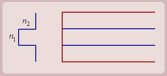
Figure (5): Step Index Fiber (Refractive index profile)
For this fiber the refractive index of the core is constant (see Fig 5). Since refractive index profile looks like a pulse or step, this kind of fiber is called the STEP INDEX FIBER. This structure is useful for analyzing propagation of light inside an optical fiber. Generally it is not used in practice because data transfer rate in this fiber is the lowest.
Just as a small exercise we can ask, what kind of pulse broadening occurs in a step index fiber if we do not use cladding?
Let us take 1Km of the optical fiber.
Since ![]() and
and ![]() ,
,
Bandwidth![]()
So if we make a cladding-less optical fiber, its light launching efficiency is excellent but it has hardly any bandwidth. Even an electrical cable is better than the optical fiber.
Important Conclusion: The cladding is an essential part of an optical fiber. It does not just provide the mechanical support but increases the bandwidth of the fiber.
We can observe from the expression for pulse broadening that ![]() keeping all other parameters constant.
keeping all other parameters constant.
Since![]() , we get
, we get
![]() BW
BW![]()
![]()
![]() .
.
Important: We can trade in the bandwidth for the length and vice versa. That is, we can send low bit rate signals over long distances and high bit rate signals only over short distances.
2. GRADED INDEX FIBER
(a) In a step index fiber since the refractive index is constant inside the core, the velocity of all the rays is constant and hence there is travel time difference between different rays. If we develop a system where the rays which travel longer distances travel with higher velocities and the rays which travel shorter distances travel with lower velocities, the pulse spread on the fiber can be reduced and consequently the bandwidth can be increased.
(b) The ray which is at a higher angle, should speed up and the ray which is along the axis of the fiber should travel with the slowest possible velocity.
Since velocity is inversely proportional to the refractive index, it can be manipulated by changing the refractive index of the core. The refractive index of outer layers of the core should be smaller compared to that of the inner layers, so the rays that go in the outer layers, travel faster.
So we find that for reducing dispersion, the refractive index at the center should be maximum and it should gradually decrease from the center to the core-cladding interface. The rays that go at higher angles speed up and the dispersion gets reduced. 2
In this fiber we grade the refractive index profile of the core and consequently it is called the graded index fiber.
A graded index fiber and the ray propagation is shown in the figure 6:
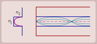
Figure (6): (Graded Index Profile)
Therefore, in practice, even for LANs, we use GIF (Graded Index Fiber) instead of SIF (Step Index Fiber).
3. SINGLE MODE OPTICAL FIBER
The light basically consists of wave fronts. A line perpendicular to a wave front is called the ray. Light is an electromagnetic wave and when we say it travels like a ray it is a collection of wavefronts which move.
Let us take an optical fiber with light rays propagating in it. The rays and the wave fronts which are perpendicular to the rays, are as shown in figure 7:
![]()
![]()
Figure (7): Core of optical fiber, rays with wave fronts
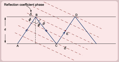
Let us consider a phase front corresponding to the ray ![]() and passing through the point
and passing through the point![]() . This phase front also meets the ray
. This phase front also meets the ray![]() at point
at point![]() . In other words, the phase of the ray at
. In other words, the phase of the ray at![]() (just before the reflection) is same as that of the ray at point
(just before the reflection) is same as that of the ray at point![]() . That is to say that the phase change corresponding to the distance
. That is to say that the phase change corresponding to the distance![]() added with the phase
added with the phase![]() of the reflection coefficient at points
of the reflection coefficient at points ![]() and
and![]() should be a multiple of
should be a multiple of![]() . This is what is called the condition for the constructive interference.
. This is what is called the condition for the constructive interference.
From simple geometric considerations we have
phase change from![]() to
to![]() is
is

For constructive interference the phase change should be multiple of![]()
![]()
Simplifying equations we get a condition for sustained propagation of light rays inside the core as
![]()
It can be noted that for ![]() (i.e. the ray along the axis of the fiber),
(i.e. the ray along the axis of the fiber), ![]() and the condition is satisfied with
and the condition is satisfied with ![]() for any value of
for any value of ![]() .
.
As ![]() increases (either due to increase of the diameter of the core or refractive index of the core, or decrease in wavelength) more values of
increases (either due to increase of the diameter of the core or refractive index of the core, or decrease in wavelength) more values of ![]() satisfy the condition and therefore have sustained propagation inside the fiber.
satisfy the condition and therefore have sustained propagation inside the fiber.
The above phase condition can be satisfied only by discrete rays entering the structure i.e. rays at finite number of angles are accepted by the optical fiber. The ensemble of rays entering at a specific angle from the axis of the fiber gives discrete optical intensity distributions. These are called the modes of an optical fiber.
From the expression of the phase matching condition we find that as d increases, the number of rays accepted by the optical fiber increases and as d decreases the number of rays decreases.
Since the dispersion is due to presence of multiple rays (modes), if only one ray is made to propagate inside the fiber, there is no dispersion. So if we take a value of ![]() small enough such that it satisfies the phase condition only the lowest value of
small enough such that it satisfies the phase condition only the lowest value of![]() , only one mode will propagate inside the fiber.
, only one mode will propagate inside the fiber.
The lowest value of ![]() corresponds to the ray traveling along the axis of the fiber. In fact this ray does not have any constraint on the size of the fiber etc, as it does not really go through the total internal reflection at the core cladding boundary. This ray therefore always propagates.
corresponds to the ray traveling along the axis of the fiber. In fact this ray does not have any constraint on the size of the fiber etc, as it does not really go through the total internal reflection at the core cladding boundary. This ray therefore always propagates.
The optical fiber in which only one ray travels along the axis of fiber is called the single mode optical fiber.
Single mode optical fiber is the best amongst the three types of fibers, namely the step index fiber, GI fiber and the single mode fiber.
In a long distance communication, we use single mode optical fiber, whereas in LANs we generally use graded index optical fiber.
Note: For single mode optical fiber however we have to use a source like laser because the diameter of the fiber is very small and without a highly collimated beam, sufficient light can not be launched inside the fiber.
The three types of fibers have typical diameters as follows:
OPTICAL FIBERS CORE DIAMETER.
SM ![]()
GRADED INDEX ![]()
STEP INDEX ![]()
Note: The Cladding Diameter for all types of fibers has been standardized to ![]()
Limitations of the Ray-model
(1) The ray model gives an impression that during total internal reflection the energy is confined to the core only. However, it is not so. In reality the optical energy spreads in cladding also.
(2) The ray model does not speak of the discrete field patterns for propagation inside a fiber.
(3) The ray model breaks down when the core size becomes comparable to the wavelength of light. The ray model therefore is not quite justified for a SM fiber.
The limitations of the Ray model are overcome in the wave model discussed in the next module.
Source:http://www.nptel.ac.in/courses/117101054/Optical%20Communication/Ray-Model.doc
Web site to visit: http://www.nptel.ac.in
Author of the text: indicated on the source document of the above text
If you are the author of the text above and you not agree to share your knowledge for teaching, research, scholarship (for fair use as indicated in the United States copyrigh low) please send us an e-mail and we will remove your text quickly. Fair use is a limitation and exception to the exclusive right granted by copyright law to the author of a creative work. In United States copyright law, fair use is a doctrine that permits limited use of copyrighted material without acquiring permission from the rights holders. Examples of fair use include commentary, search engines, criticism, news reporting, research, teaching, library archiving and scholarship. It provides for the legal, unlicensed citation or incorporation of copyrighted material in another author's work under a four-factor balancing test. (source: http://en.wikipedia.org/wiki/Fair_use)
The information of medicine and health contained in the site are of a general nature and purpose which is purely informative and for this reason may not replace in any case, the council of a doctor or a qualified entity legally to the profession.
The texts are the property of their respective authors and we thank them for giving us the opportunity to share for free to students, teachers and users of the Web their texts will used only for illustrative educational and scientific purposes only.
All the information in our site are given for nonprofit educational purposes