
A pipe thread is a spiral ridge on the end of a pipe that enables pipes to be joined together. For male fittings, pipe thread appears on the outer diameter of the pipe; if female, the pipe thread appears on the inner diameter. By rotating a male pipe end into a female pipe thread, the two fittings become joined. Since male and female pipe thread must align successfully to form a connection, manufacturers follow pipe thread industry standards. The two main pipe thread standards are as follows:
Pipe threads are used to make not only a mechanical joint but also a leakproof liquid seal. This is accomplished by machining the thread form on a taper and using pipe sealant to fill any voids between the two threads which could cause a spiral leak. In both thread standards there are 2 different types of threads:
A parallel pipe thread only forms a mechanical seal and is not used for liquid seal applications. While a tapered pipe thread that can make a close-fitting wet seal. Pipe threads used for liquid joints can be divided into two types:
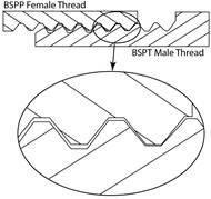
In the nineteenth century, many different types of screw threads were required for hydraulic and pneumatic circuits as well as fastening components. As a result, manufacturers started to devise their own fastening systems. This resulted in compatibility problems. The English mechanical engineer and inventor, Sir Joseph Whitworth devised a uniform threading system in 1841 to address the incompatibility problem. The Whitworth thread form is based on a 55 degree thread angle with rounded roots and crests. The joint is made self sealing by cutting at least one of the threads on a taper (usually the male thread). This became known as the British Standard Pipe thread has been adopted internationally for interconnecting and sealing pipe ends. The image below shows a BSPT (BSP Taper) male thread sealing in BSPP (BSP Parallel) female coupling.
BSPT male sealing in BSPP female
To achieve the taper the bottoms of the threads aren't on a cylinder, but on a cone; with a taper which is 1⁄16 inch in an inch, which is the same as 3/4 inch in a foot. The taper divided by a centre line yields an angle 1° 47' 24" or 1.7899° as measured from the centre axis. Commonly-used sizes are ⅛, ¼, ⅜, ½, ¾, 1, 1¼, 1½, and 2”, available at most suppliers. Larger sizes are used less frequently because other methods of joining are more practical for 3” and above in most applications.
The most important point to understand about pipe threads is that their size refers to the diameter of the hole going through the fitting (i.e. where the media travels such as air or oil, etc), and not the diameter of the thread itself.
In America, William Sellers set the standard for nuts, bolts, and screws which became the National Pipe Tapered Thread (NPT) in 1864. His 60 degree thread angle with flat crests and roots is the American standard for tapered threads used to join pipes and fittings. The ANSI/ASME standard B1.20.1 covers threads of 60-degree form in sizes from 1/16” to 24” Nominal Pipe Size (NPS).
The taper rate for NPT threads is the same as BSPT (3/4” per foot) measured by the change of diameter (of the pipe thread) over distance. Sometimes NPT threads are referred to as MPT ('Male Pipe Thread'), MNPT, or NPT(M) for male (external) threads; and FPT ('Female Pipe Thread'), FNPT, or NPT(F) for 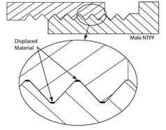
female (internal) threads.
NPT male sealing in NPT female (Hand tight plus 1 turn)
Because of the taper, a pipe thread can only screw into a fitting a certain distance before it jams. The standard specifies this distance as the length of hand tight engagement, the distance the pipe thread can be screwed in by hand. It also specifies another distance – the effective thread, this is the length of the thread which makes the seal on a conventional machined pipe thread. For pipefitters, instead of these distances, it is more convenient to know how many turns to make by hand and how many with a wrench. A simple rule of thumb for installing tapered pipe threads, both metal and plastic, is finger tight plus one to two turns with a wrench. Torque installation values can be determined per application, but due to the variations involved in pipe joints such as disimiliar materials of male and female threads, type of sealants used, and internal variations in product wall thickness, a standard torque specification cannot be generically applied. The table below compares the critical dimensions of BSP and NPT threads and gives the number of turns to hand tighten.
|
British BSP |
American NPT |
|
||
Nominal Size |
Actual OD |
Threads per inch |
Actual OD |
Threads per inch |
Turns for a hand tight joint |
1/8" |
0.383” |
28 |
0.405” |
27 |
≈ 3.3 turns |
1/4" |
0.518” |
19 |
0.540” |
18 |
≈ 3.1 turns |
3/8" |
0.656” |
19 |
0.675” |
18 |
≈ 3.3 turns |
1/2" |
0.825” |
14 |
0.840” |
14 |
≈ 3.4 turns |
3/4" |
1.041” |
14 |
1.050” |
14 |
≈ 3.7 turns |
1" |
1.309” |
11 |
1.315” |
11.5 |
≈ 3.7 turns |
1 1/4" |
1.650” |
11 |
1.660” |
11.5 |
≈ 3.8 turns |
1 1/2" |
1.882” |
11 |
1.900” |
11.5 |
≈ 3.8 turns |
2" |
2.347” |
11 |
2.375” |
11.5 |
≈ 3.9 turns |
Comparison of BSP v NPT threads and turns to hand tighten
A hand held threading handle is made up of a stock to which the handles are attached and to which the cutting die is inserted in. There are two sets of set screws on the stock, one set for holding the dies in place and the other set for adjusting the dies. On the stock there is a deep mark to correspond with the standard thread mark on the dies. On the opposite side of the stock there is a place for the follower which helps to guide the cutting dies onto the pipe that is to be threaded. The photos below are typically representative of manual threading handles.
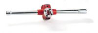
Manual threading handles, ratchets and cutting dies
A threading ratchet has only one handle and a ratchet action which allows it to be used in confined spaces. Their size and convenience makes it possible for pipefitters to cut a section of pipe and add the right configuration of threads to pipes while at the job site or clean up an existing thread which had become damaged.
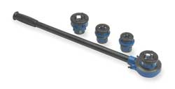
A full set of stocks and dies is composed of right and left dies from 1⁄8” up to 1”, with a guide for each size. The dies will have marked on them 1" R which will cut a 1” right handed thread, (if 1-inch left were wanted, the mark would be 1" L).
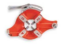
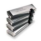
Die head and set of universal cutting dies for a range of thread sizes
A threading machine uses a set of universal machine dies which are fixed in the die head and are numbered to be inserted in the correct sequence. One set of these dies can cut a range of pipe sizes usually from 1” to 2” threads and 2½” to 4” threads. The photos above show a die head with the positions numbered and a set of universal dies for cutting threads on 1” to 2” pipe.

Portable handheld electric units are relatively inexpensive, lightweight and are ideal for maintenance and repair workers, as well as service plumbers. They can thread pipe from 1/8” to 2" in diameter and usually come in a durable carrying case with a set of 6 right hand dies to cover all common pipe sizes in this range.
Hand held threading machine for light work 1/8” to 2”
At one time, pipe threading machines were the province of large scale manufactures and tended to focus on the mass production of threaded steel pipes. Along with machining the specified thread design, the machines would also cut the pipe into workable sections, as well as ream out the pipe to ensure there were no defects in the pipe proper. Over time, the process for pipe threading and pipe cutting was refined, making it possible to produce completed goods for sale in a very short period of time. The uses of machines allow the threading process to produce uniform pipe threads that are uniform in nature.
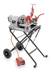
Workshop threading machine with foot pedal control
For heavier duty or high volume repetitive work a pipe fitter would typical use a power threading machine. This type of machine can thread a wide range of pipe including black, galvanized and plastic-coated pipe, together with stainless steel and heavy-wall conduit, as well as rod up to 30 Rockwell C. These types of units typically operate at 36 RPM for 1/4" to 2" pipe and at 12 RPM for 2 1/2" to 4" pipes. There is constant and proper lubrication of dies and the workpiece with through-head oiling and a universal receding die head allows cutting of tapered or straight BSPT/BSPP or NPT/NPSM threads. Motor control Reverse/Off/Forward, is achieved with a heavy-duty rotary-type integral foot switch which allows the pipe fitter have both hands free for the work piece.
Along with increased efficiency and lower maintenance costs, there are pipe threading machines that are designed to work with materials other than metal. Pipes made with various types of plastic or resin materials can now be ran through pipe threading machines with no fear of overheating and thus damaging the finished product. There are many manufactures who use these machines to prepare low cost plastic piping making use of universally recognized thread configurations.
Threading oils are used to cool and lubricate the cutting die and work piece. The use of threading oils assists the threading process for the following reasons:
There are various kinds of cutting fluids specially formulated to maximize wear resistance and can increases die life up to 60% and significantly reduce operating costs by up to 30%. Like thread sealants they should be selected depending on the piping service being installed and the pipe material being threaded.
The taper on BSPT threads allows them to form a seal when torqued as the flanks of the threads compress against each other, as opposed to parallel/straight thread fittings or compression fittings in which the threads merely hold the pieces together and do not provide the seal. However a clearance remains between the crests and roots of the threads, resulting in a leakage around this spiral. This means that BSPT fittings must be made leak free with the aid of thread seal tape or a thread sealant compound. The most common pipe thread tape is polytetrafluoroethylene or (PTFE) tape. The tape should be wound tight around the male pipe threads, running in the same direction as the lead thread so that the turning motion of joining the pipes follows the tape's winding direction. Sealing tape makes it easy to drive the male pipe deeper by allowing the threads to slip past one another, while filling minute gaps to prevent seepage. Pipe thread tape also makes it easier to disassemble the joint later, if need be, by reducing thread galling, or the tendency of some types of pipe threads to stick together over time.
Special grease free PTFE tape which will not support combustion should be used on threaded joints on oxygen lines as the standard PTFE tape can self ignite when the oils and pure oxygen combine.
Thread sealants can also be used for sealing threaded joints and allow easy disassembly of joints without compromising thread integrity and prevents thread corrosion. There are different types of sealant for different applications depending on the type of pipe, temperature of service and the fluid being carried in the pipe. It is important that sealant being used should non-toxic, lead-free formulas which won’t harden or freeze.
When operating pipe threading equipment the operator should be properly trained and supervised and observe all the general safe working procedures required for the threading processes. While this is not meant to be an exhaustive list some specific points to note for pipe threading are as follows:
Always -
The following are generic guidelines for pipe threading equipment, as there are many different suppliers of threading equipment it is not possible to provide a specific check list. This information does not replace the manufacturer’s instruction guide, it is meant only to acquaint the operator with some basic functions and safety tips that he/she must be aware of.
Threading equipment varies considerably in their control and safety arrangements and therefore it is important to verify that actual equipment used is set-up correctly.
Please refer to your instructor for specific instruction and additional safety information where required.
The following tools will be required to complete a threaded joint:
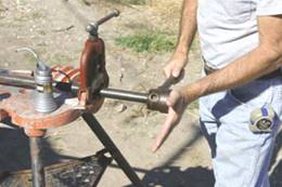
Secure the pipe in the pipe vice and cut to the desired length. Then, fit the threading die over the end of the pipe. The cutting starts with a fine thread on the die, cutting fluid must be used to lubricate the pipe and die. Turn the handle of the die clockwise half a turn at a time, and then back it off a bit in order to eject the metal chips. The dies are run up on the pipe until the pipe extends through the face of the dies one thread. Oil is put on the pipe and the dies at least twice during the cutting. Ensure that the die is kept perpendicular to the pipe at all times to ensure the thread is square and even. The inner threads or those away from the pipe end are not cut as deep, providing a taper that creates a tighter joint. Remove the pipe from the vise, stand it on end, and tap to remove any metal chips or particles that may be lodged inside.
Threading the end of a pipe
Then clean off the oil with a soft rag. Be careful; the threads are very sharp and can cut your hands. Insert the correct size reamer inside the pipe to ensure any sharp burrs are removed from the inside of the pipe.
The threaded pieces are then joined together using couplings or fittings. A sealing material must be used on the threads at each joint. This can be either Teflon tape, or a pipe thread sealing compound.
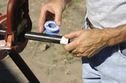
Teflon tape or pipe thread sealing compound is placed on the threads.
With the sealing material in place, hand-tighten the pipe and coupling or fitting. Then, using pipe wrenches, one on the pipe and one on the fitting, tighten one and a half more turns.
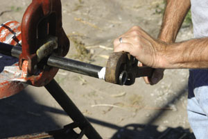
Tighten the coupling or fitting by turning one and a half more turns after hand tight
Steel or galvanized piping is heavy and it must be well supported, especially at each joint or coupling. Use pipe clips at regular intervals and close to threaded joints to ensure that the pipe is well supported and does not sag. CAUTION: It is extremely important to test all joints for leaks. Use a bit of water mixed with dish detergent and a soft brush to coat the solution over all joints. Any bubbles produced indicate a leak. Shut off the gas, retighten the joint and retest.

Pressure testing of pipelines should normally be carried out using water. Only in exceptional circumstances should pneumatic pressure testing using compressed inert gas or air be used, and then only under carefully controlled conditions. The reason for this is because water is virtually incompressible (as are other liquids) and only a small quantity of energy needs to be introduced to increase the pressure significantly. Air, however, (like all gases) is compressible and, as a result, much more energy has to be put into the gas to raise its pressure. In fact, at the pressure ranges normally used for testing water-piping systems 200 times more energy is stored in compressed gas compared to water at the same pressure and volume. So, should a joint, pipe, or any other component fail under test pressure when using compressed gas, the energy can be released with deadly force! However, where water leakage would cause unacceptable damage to property, a pneumatic leak test (at approx. 20mbar) with a soap bubble test at all joints can be used first, followed by a hydraulic pressure test.
Before pressure tests are carried out it is important to verify the following:
Test pack drawings and documentation should be submitted to the client or his representative in advance of any testing. This is required to give ample time for the system to be reviewed and the necessary personnel to be notified and work permits to be prepared.
Prior to execution of any pressure test, a representative for the contractor must complete a pre-test installation check on the pipeline to be tested. A record at this inspection must be completed, signed by the contractor and verified by the client or his nominated representative before testing can commence. This pre-test installation check should include at a minimum (but not be limited to) the following:
Depending on the system specification the finished installation must satisfy one or both of the following tests.
Section of pipe passing through clean or sensitive areas, may be checked for leaks using a low pressure air test prior to undergoing a hydrostatic test if requested by the client.
The table below indicates the typical information recorded on a pressure test certificate and the verification steps and signatures required.
Typical Pressure test certificate with sign offs for each step
Source: http://local.ecollege.ie/Content/APPRENTICE/liu/pipefitting/word/M3_U6_Pipe%20Threading%20and%20Testing.doc
Web site to visit: http://local.ecollege.ie
Author of the text: indicated on the source document of the above text
If you are the author of the text above and you not agree to share your knowledge for teaching, research, scholarship (for fair use as indicated in the United States copyrigh low) please send us an e-mail and we will remove your text quickly. Fair use is a limitation and exception to the exclusive right granted by copyright law to the author of a creative work. In United States copyright law, fair use is a doctrine that permits limited use of copyrighted material without acquiring permission from the rights holders. Examples of fair use include commentary, search engines, criticism, news reporting, research, teaching, library archiving and scholarship. It provides for the legal, unlicensed citation or incorporation of copyrighted material in another author's work under a four-factor balancing test. (source: http://en.wikipedia.org/wiki/Fair_use)
The information of medicine and health contained in the site are of a general nature and purpose which is purely informative and for this reason may not replace in any case, the council of a doctor or a qualified entity legally to the profession.
The texts are the property of their respective authors and we thank them for giving us the opportunity to share for free to students, teachers and users of the Web their texts will used only for illustrative educational and scientific purposes only.
All the information in our site are given for nonprofit educational purposes