
A pipe is round tubular section or hollow cylinder used mainly to convey media. It may also be used for structural applications; however in this instance we will concentrate on its use in the process industry. Pipe is generally manufactured to several long-standing and broadly applicable industrial standards. While similar standards exist for specific industry application tubing, tube is often made to custom sizes and a broader range of diameters and tolerances. Many industrial and government standards exist for the production of pipe and tubing. The term "tube" is also commonly applied to non-cylindrical sections (i.e. square or rectangular tubing).
In general terms the appellations pipe and tube are almost interchangeable, but in the pipe fitting industry and engineering discipline the terms are uniquely defined.
Pipe
Depending on the applicable standard to which it is manufactured, pipe is specified by the internal diameter (ID) and a wall thickness, the inside diameter called the nominal diameter may not exactly match the pipe size as it varies with the wall thickness. For example the ID of an 8” pipe varies from 213.54mm ID for Sch5 pipe to 193.68mm for Sch40 pipe.
Tube
Tube is most often defined by the outside diameter (OD) and a wall thickness. Therefore 8” tube would have an outside diameter of 203.2mm.
As there are many different types of pipe and tube and different standards that are applicable for each, it is not possible to give a definitive list of the exact information required to be marked on pipe and tube; however the common requirements would be as follows and should be continuously marked down its whole length:
There are two main processes for metallic pipe manufacture. Seamless (SMLS) pipe is formed by drawing a solid billet over a piercing rod to create the hollow shell. Seamless pipe is generally more expensive to manufacture but provides higher pressure ratings. Welded pipe is formed by rolling plate and welding the seam. The weld seam is formed by Electric Resistance Welded (ERW) or Electric Fusion Welded (EFW) and is usually ground flush with the parent material as part of the manufacturing process. The weld zone can also be heat treated, so the seam is less visible. Welded pipe often has tighter dimensional tolerances than seamless, and can be cheaper if manufactured in large quantities. Large diameter pipe (about 10” or greater) may be ERW, or Submerged Arc Welded (SAW) pipe. Metal tubing due to the thinner wall thickness can be extruded but not always and many sanitary tubes such as hygienic stainless steel has a welded seam. Plastics are generally extruded due to the ease of handling the base materials. The illustration below shows the different ways that pipe are manufactured:
There are limitations to the hot manufacturing processes for pipe and tube such as:
For these reasons pipe and tube are cold worked after extrusion or seam welding.
Methods of forming Pipe and Tube
Non-destructive tests do not damage the pipe or tube being tested and so they are frequently incorporated into the end of the production line. The following give a brief explanation of the common types of NDT available:
Ultrasonic Testing
This test involves ultrasonic sound waves being aimed, via a coupling medium, at the material to be tested. A proportion is bounced back at the interface but the remainder enter the material and bounce from the internal surface, to the external surface, where a transducer converts them into electrical energy. This is then monitored on a cathode ray tube where results are compared with those from a calibration standard. Any deviations from the standard are visible, thus indicating cracks or internal defects.
Eddy-Current Testing
This involves inducing eddy currents into the material by exciting a coil which surmounts two narrow search coils surrounding the material. Any discontinuities in material are found by comparing the electrical conditions that exist in the two search coils. The fault signals are amplified and can be shown on a cathode ray tube or as an audible signal.
Hydrostatic Testing
This is used to test the manufactured items under a pressure equivalent to or greater than pressure to be encountered in service. It involves filling the tube with water, which cannot be compressed, and increasing the pressure inside the tube to that specified.
Magnetic Particle Testing
This method of testing is used when trying to detect discontinuities in material of ferromagnetic structure. The method is based on the principle that an imperfection will cause a distortion in the magnetic field pattern of a magnetised component. The imperfection can be revealed by applying magnetic particles to the component during or after magnetisation.
Radiographic (X-Ray) Testing
This is usually used to determine whether a weld is sound. It involves subjecting a weld or weld area to an X-Ray source with an X-Ray sensitive film plate on the under side of the weld. The results are shown on the developed film (a photomicrograph) and interpreted according to specification.
Dye-Penetrant Test
This is used to detect cracks and involves spraying a dye on the area to be tested. After allowing time for penetration the surplus dye is removed and the area is then sprayed with a white developer. Any faults are revealed as coloured lines or spots caused by the developer absorbing the dye seeping from the cracks. If more sensitive results are required, a fluorescent dye is used and the same process is followed. When viewed under ultraviolet light any defects show as a highly fluorescent line or spot.
Pipe may be made from a variety of materials. In the past, materials have included wood and lead (Latin for lead is plumbum, from which we get the word plumbing). Nowadays the manufacturing of pipe uses many different materials including ceramics, fiberglass, concrete, plastics and metals.
Pipes may be made from concrete or ceramic materials. These pipes are usually used for low pressure applications such as gravity flow or drainage underground. Concrete pipes usually have a receiving bell or a stepped fitting, with various sealing methods applied at installation. Ceramic pipes are used for underground drainage which may be exposed to corrosive chemicals. These types of pipes are relatively inexpensive for the diameters in question and allow for ease of installation in rough site conditions.
Plastic tubing is widely used for its light weight, chemical resistance, non-corrosive properties, and ease of making connections. Plastic materials include polyvinyl chloride (PVC), chlorinated polyvinyl chloride (CPVC), fibre reinforced plastic (FRP), reinforced polymer mortar (RPMP), polypropylene (PP), polyethylene (PE), cross-linked high-density polyethylene (PEX), polybutylene (PB), and acrylonitrile butadiene styrene (ABS), for example.
Metallic pipes are commonly made from steel or iron; the metal chemistry and its finish are peculiar to the use fit and form. Typically metallic piping may be made of steel or iron, such as unfinished, black (lacquer) steel, carbon steel, stainless steel or galvanized steel, brass, and ductile iron. Aluminium pipe or tubing may be utilized where iron is incompatible with the service fluid or where weight is a concern; aluminium is also used for heat transfer tubing such as in refrigerant systems. Copper tubing is popular for domestic water (potable) plumbing systems; copper may be used where heat transfer is desirable (i.e. radiators or heat exchangers). Inconel, chrome moly, and titanium steel alloys are used for high temperature and pressure piping in process systems where corrosion resistance is important.
Stainless steel pipe and tubing are used for a variety of reasons: to resist corrosion and oxidation, to resist high temperatures, for cleanliness and low maintenance costs, and to maintain the purity of materials which come In contact with stainless. There are more than 60 grades of stainless steel available. The ability of stainless steel to resist corrosion is achieved by the addition of a minimum of 12% chromium to the iron alloy. Additions of other elements affect other properties. The inherent characteristics of stainless steel permit the design of thin wall piping systems without fear of early failure due to corrosion. Because of the thinner wall thickness of stainless steel tube it is not possible to thread tube therefore this was overcome by fusion welding to join such pipe and tubing.
Type 304 stainless is the most widely used analysis for general corrosive resistant tubing and pipe applications, it is used in chemical plants, refineries, paper mills, and food processing industries. Type 304 has a maximum carbon content of .08%. It is not recommended for use in the temperature range between 400°C and 900°C due to carbide precipitation at the grain boundaries which can result in inter-granular corrosion and early failure under certain conditions.
Type 304L. Is the same as 304 except that a 0.03% maximum carbon content is maintained which precludes carbon precipitation and permits the use of this analysis in welded assemblies under more severe corrosive conditions. Type 318 is much more resistant to pitting than other chromium nickel alloys due to the addition of 2% to 3% molybdenum. it is particularly valuable wherever acids, brines, sulphur water, seawater or halogen salts are encountered. Type 316 is widely used in the sulphite paper industry and for manufacturing chemical plant apparatus, photographic equipment, and plastics. Type 316L, like 304L, is held to a maximum carbon content of .03%. This permits its use in welded assemblies without the need of final heat treatment. It is used extensively for pipe assemblies with welded fitting.
Manufacturing standards for pipes commonly require a test of chemical composition and a series of mechanical strength tests for each heat of pipe. A heat of pipe is all forged from the same cast ingot, and therefore had the same chemical composition. Mechanical tests may be associated to a lot of pipe, which would be all from the same heat and have been through the same heat treatment processes. The manufacturer performs these tests and reports the composition in a mill traceability report and the mechanical tests in a material test report, both of which are referred to by the acronym MTR. Material with these associated test reports is called traceable. For critical applications, third party verification of these tests may be required; in this case an independent lab will produce a certified material test report (CMTR), and the material will be called certified. By etching the heat number on the components made from this batch of material, it ensures that there is full traceability from the component to the material certificate and therefore the chemical composition of the component is known.
Maintaining the traceability between the material and this paperwork is an important quality assurance issue. QA often requires the heat number to be written on the pipe. Precautions must also be taken to prevent the introduction of counterfeit materials. As a back up to etching/labelling of the material identification on the pipe, Positive Material Identification (PMI) is performed using a handheld device; the device scans the pipe material using an emitted electromagnetic wave (x-ray fluorescence/XRF) and receives a reply that is spectrographically analysed.

Pipe sizes can be confusing because the terminology may relate to historical dimensions. For example, a half-inch iron pipe doesn't have any dimension that is a half inch. Initially, a half inch pipe did have an internal dimension of 0.5” but it also had thick walls. As technology improved, the wall thickness got thinner (saving material costs), but the outside diameter stayed the same so it could mate with existing older pipe. The history of copper pipe is similar. In the 1930s, the pipe was designated by its internal diameter and a 1/16” wall thickness. Consequently, a 1” copper pipe would have a 1 1/8” outside diameter. The outside diameter was the important dimension for mating with fittings. The wall thickness on modern copper is usually thinner than 1/16”, so the internal diameter is only "nominal" rather than a controlling dimension. Newer pipe technologies sometimes adopted a sizing system as it’s own. PVC pipe uses the nominal pipe size.
Nominal Pipe Size (NPS) is a North American set of standard sizes for pipes used for high or low pressures and temperatures. Pipe size is specified with two non-dimensional numbers: a nominal pipe size (NPS) based on inches, and a schedule (Sch.) which specifies the wall thickness. The European designation equivalent to NPS is DN (Diamètre Nominal/nominal diameter), in which sizes are measured in millimetres. The term NB (nominal bore) is also frequently used interchangeably with NPS. Designating the outside diameter allows pipes of the same size to be fit together no matter what the wall thickness.
Pipe sizes are documented by many different international standards, including some of the following:
Since the outside diameter is fixed for a given pipe size, the inside diameter will vary depending on the wall thickness of the pipe. For example, 2" Schedule 80 (or Sch 80) pipe has thicker walls and therefore a smaller inside diameter than 2" Schedule 40 pipe. The table below lists the dimensions for 1/8” to 3” Pipe in both inches and millimetres and gives the different wall thicknesses for the different schedules.
NPS Inches |
DN |
OD |
Wall Thickness - inches (millimetres) |
|||
SCH 5 |
SCH 10 |
SCH 40 |
SCH 80 |
|||
⅛ |
6 |
0.405 in (10.29 mm) |
0.035 in (0.889 mm) |
0.049 in (1.245 mm) |
0.068 in (1.727 mm) |
0.095 in (2.413 mm) |
¼ |
8 |
0.540 in (13.72 mm) |
0.049 in (1.245 mm) |
0.065 in (1.651 mm) |
0.088 in (2.235 mm) |
0.119 in (3.023 mm) |
⅜ |
10 |
0.675 in (17.15 mm) |
0.049 in (1.245 mm) |
0.065 in (1.651 mm) |
0.091 in (2.311 mm) |
0.126 in (3.200 mm) |
½ |
15 |
0.840 in (21.34 mm) |
0.065 in (1.651 mm) |
0.083 in (2.108 mm) |
0.109 in (2.769 mm) |
0.147 in (3.734 mm) |
¾ |
20 |
1.050 in (26.67 mm) |
0.065 in (1.651 mm) |
0.083 in (2.108 mm) |
0.113 in (2.870 mm) |
0.154 in (3.912 mm) |
1 |
25 |
1.315 in (33.40 mm) |
0.065 in (1.651 mm) |
0.109 in (2.769 mm) |
0.133 in (3.378 mm) |
0.179 in (4.547 mm) |
1¼ |
32 |
1.660 in (42.16 mm) |
0.065 in (1.651 mm) |
0.109 in (2.769 mm) |
0.140 in (3.556 mm) |
0.191 in (4.851 mm) |
1½ |
40 |
1.900 in (48.26 mm) |
0.065 in (1.651 mm) |
0.109 in (2.769 mm) |
0.145 in (3.683 mm) |
0.200 in (5.080 mm) |
2 |
50 |
2.375 in (60.33 mm) |
0.065 in (1.651 mm) |
0.109 in (2.769 mm) |
0.154 in (3.912 mm) |
0.218 in (5.537 mm) |
2½ |
65 |
2.875 in (73.02 mm) |
0.083 in (2.108 mm) |
0.120 in (3.048 mm) |
0.203 in (5.156 mm) |
0.276 in (7.010 mm) |
3 |
80 |
3.500 in (88.90 mm) |
0.083 in (2.108 mm) |
0.120 in (3.048 mm) |
0.216 in (5.486 mm) |
0.300 in (7.620 mm) |
While steel pipe has been produced for about 150 years, newer pipe materials such as PVC and galvanized pipe adopted the older steel pipe dimension conventions. Many different standards exist for pipe sizes, and their prevalence varies depending on industry and geographical area. The pipe size designation generally includes two numbers; one that indicates the outside (OD) or nominal diameter, and the other that indicates the wall thickness. In the early twentieth century, American pipe was sized by inside diameter. This practice was abandoned to improve compatibility with pipe fittings that must usually fit the OD of the pipe, but it has had a lasting impact on modern standards around the world.
Copper tubing was introduced in about 1900, but didn't become popular until approximately 1950, depending on local building code adoption. Copper plumbing tube for residential plumbing follows an entirely different size system, often called Copper Tube Size (CTS); see table below. It’s nominal size is neither the inside nor outside diameter. Plastic tubing, such as PVC and CPVC, for plumbing applications also has different sizing standards. Common wall-thicknesses of copper tubing are "Type K", "Type L" and "Type M"
Nominal size |
Outside diameter (OD) (inches) |
Inside diameter (ID) (inches) |
||
Type K |
Type L |
Type M |
||
3/8 |
1/2 |
0.402 |
0.43 |
0.45 |
1/2 |
5/8 |
0.528 |
0.545 |
0.569 |
5/8 |
3/4 |
0.652 |
0.668 |
0.69 |
3/4 |
7/8 |
0.745 |
0.785 |
0.811 |
1 |
1 1/8 |
0.995 |
1.025 |
1.055 |
1 1/4 |
1 3/8 |
1.245 |
1.265 |
1.291 |
1 1/2 |
1 5/8 |
1.481 |
1.505 |
1.527 |
2 |
2 1/8 |
1.959 |
1.985 |
2.009 |
2 1/2 |
2 5/8 |
2.435 |
2.465 |
2.495 |
3 |
3 1/8 |
2.907 |
2.945 |
2.981 |
Sizes for copper tubes
Types K and L are generally available in both hard drawn "sticks" and in rolls of soft annealed tubing, whereas type M is usually only available in hard drawn "sticks". Thin-walled types used to be relatively inexpensive, but since 2002 copper prices have risen considerably due to rising global demand and a stagnant supply.
In the plumbing trade the size of copper tubing is measured by its nominal diameter (average inside diameter). Some trades, heating and cooling technicians for instance, use the outside diameter (OD) to designate copper tube sizes. The HVAC tradesman also use this different measurement to try and not confuse water pipe with copper pipe used for the HVAC trade, as pipe used in the Air-conditioning trade uses copper pipe that is made at the factory without processing oils that would be incompatible with the oils used to lubricate the compressors in the AC system. The OD of copper tube is always 1/8th inch larger than its nominal size. Therefore, 1" nominal copper tube and 1-1/8th" ACR tube are exactly the same tube with different size designations. The wall thickness of the tube, as mentioned above, never affects the sizing of the tube. Type K 1/2" nominal tube, is the same size as Type L 1/2" nominal tube (5/8" ACR).
Stainless steel pipes, which were coming into more common use in the mid 20th century, permitted the use of thinner pipe walls with much less risk of failure due to corrosion. This led to the development of stainless steel tubing, which due to it’s thinner wall it could not be threaded together according to the ASME code, and therefore was fusion welded.
This led to the development of a range of hygienic stainless steel tube and fittings which could be used in applications requiring a clean and sanitary flow of liquids and where it is essential to avoid contamination of the products being carried. These applications cover the food processing, beverage, biotech and pharmaceutical industries including breweries and dairies.
The tube and fittings are of welded construction with the internal bead rolled and polished to eliminate crevices, thus preventing interruptions to the flow and eliminating the risk of contamination or bug traps as well as facilitate easy cleaning.
Hygienic tube and fittings are manufactured to the following standards including:
Hygienic fittings are manufactured to
O/D |
Wall |
Weight |
|
In |
swg |
mm |
kg/m |
3/4 |
16 |
1.63 |
0.70 |
1 |
16 |
1.63 |
0.99 |
11/2 |
16 |
1.63 |
1.51 |
2 |
16 |
1.63 |
1.88 |
21/2 |
16 |
1.63 |
2.49 |
3 |
16 |
1.63 |
3.01 |
4 |
16 |
1.63 |
4.03 |
4 |
14 |
2.03 |
4.98 |
Sizes and weights for DN11850 Tube
O/D |
Wall |
Weight |
in |
mm |
kg/m |
1 |
1.5 |
0.90 |
11/2 |
1.5 |
1.38 |
2 |
1.5 |
1.85 |
21/2 |
1.5 |
2.34 |
3 |
1.5 |
2.81 |
4 |
2.0 |
5.02 |
Sizes and weights for ASTM 270 Tube
The manufacture and installation of pressure piping is tightly regulated by the ASME "B31" code series such as B31.1 or B31.3 which have their basis in the ASME Boiler and Pressure Vessel Code. This code has the force of law in Canada and the USA. Europe has an equivalent system of codes. Pressure piping is generally classified as pipe that must carry pressures greater than 10 to 25 atmospheres, although definitions vary. To ensure safe operation of the system, the manufacture, storage, welding, testing, etc. of pressure piping must meet stringent quality standards.
In Europe, pressure piping uses the same pipe IDs and wall thicknesses as Nominal Pipe Size, but labels them with a metric Diameter Nominal (DN) instead of the imperial NPS. For NPS larger than 14, the DN is equal to the NPS multiplied by 25. (Not 25.4) This is documented by EN 10255 (formerly DIN 2448 and BS 1387) and ISO 65, and it is often called DIN or ISO pipe. In North America and the UK, pressure piping is usually specified by Nominal Pipe Size (NPS) and schedule (SCH). Pipe sizes are documented by a number of standards, including API 5L, ANSI/ASME B36.10M in the US, and BS 1600 and BS 1387 in the United Kingdom. Typically the pipe wall thickness is the controlled variable, and the Inside Diameter (I.D.) is allowed to vary. The pipe wall thickness has a variance of approximately 12.5 percent.
The following equations and tables are based on those provided in the Process Piping Specification, ASME B31.3a-2008, ASME Code for Pressure Piping. There are four equations which may be used to calculate the ‘pressure design wall thickness’ (t) of a straight pipe subject to internal pressure, two of which are given as follows:
where:
The reasons pipe and tube are made from different materials is due the to physical properties of different materials. Properties such as:
Malleability
Malleability can be defined as the property of a metal to be deformed by compression without cracking or rupturing. This property is very useful for copper tubing systems which allows the tube to be bent to follow the required route quickly without the need for expensive and time consuming fittings:
Ductility
Ductility is a mechanical property used to describe the extent to which materials can be deformed plastically without fracture. Ductile metals lend themselves to be formed into desired cross sectional shapes easier and therefore are cheaper to manufacture
Brittleness
The tendency for a metal to crack or break with deformation. Metals displaying this property are not readily used for pipe or tube as this is a disadvantage to a material.
Hardness
Is the property of being rigid and resistant to pressure; not easily scratched. It is measured on Mohs scale. It’s presence in metals can be an advantage for high pressure systems but can be a disadvantage as it can increase machining, cutting and fabrication times.
Elasticity
The property by virtue of which a material deformed under the load can regain its original dimensions when unloaded. This property is utilized in piping system designs where pipes may expand or contract due to temperature differences. The elasticity of piping materials can help the designer cater for this.
Conductivity
The ability of a material to conduct electrical current or heat. Some piping systems high conductivity metals for high heat transfer while other piping systems use low conductivity plastic materials to prevent heat transfer.
Chemical resistance/ Resistance to Corrosion
The degree to which a material resists the corrosive action of industrial chemicals. This is probably the most significant property which affects the choice of piping material and is the biggest contributor to the price of material. Specialist alloys of stainless steel such as Hastelloy can be 10 to 20 times more expensive that standard stainless steel and can be slower to fit and weld which increase installation costs.
Source: http://local.ecollege.ie/Content/APPRENTICE/liu/pipefitting/word/M3_U1_Piping%20Materials.doc
Web site to visit: http://local.ecollege.ie/
Author of the text: indicated on the source document of the above text
A) Calculate the cross-sectional area of a piece of 60 x 60 x 6 R.H.S.
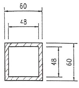
Outside area = 60 x 60 = 3600
Inside area = 48 x 48 = 2304
Cross-sectional area = 1296 mm²
B) Calculate the cross-sectional area of a piece of Ø 20 O.D. which is 6mm thick.
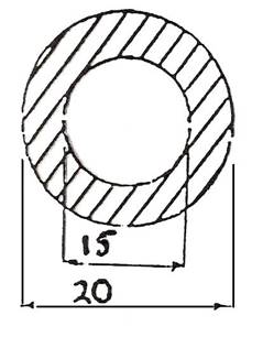
O.D. = Outside diameter,
I.D. = Inside diameter
Π = 3.14,
Ø = symbol for diameter
20mm x Π (3.14)
15mm x Π (3.14)
When you have calculated the answers, simply subtract to find the cross-sectional area.
Volume is always in m³, so the measurements you use must always be in metres, before you do any calculations.
Find the volume of the rectangular container, length 2m, width 450mm, height 750mm.
Two of the measurements are in mm (millimetres). These must be converted into metres. Since every 1000mm makes up a metre, divide the number of mm by 1000 to give metres.
So 450mm ![]() 1000 = 0.450m
1000 = 0.450m
And 750mm ![]() 1000 = 0.750m
1000 = 0.750m
Now the calculations are as before:
Volume is 2m x 0.450m x 0.750m = 0.675m³
CAPACITY is the amount of liquid which the container can hold. This is very simple to work out.
1 m³ holds 1000 litres of liquid.
So if the volume of the container is 5m³, since each cubic metre holds 1000 litres, the capacity of this container must be
5m³ x 1000 = 5000 litres
A tank with a volume of 1.175m³ will have a capacity of
1.175m³ x 1000 = 1175 litres
Remember, find volume as before, making sure that all dimensions are in metres before you start, and multiply your answer by 1000.
Find the capacity in litres of a rectangular tank 1 m long x 250mm wide x 300mm high.
First, convert all measurements into metres.
1m x .25m x .3m = 0.075m³
This figure is less than 1 cubic metre, but the principle remains the same.
Multiply the volume in cubic metres by 1000 to get the capacity in litres.
0.075 X 1000 = 75litres
Find the capacity in litres of a rectangular tank 1.5m long x 750mm wide x 1250mm deep.
Note: This time not all the measurements are given in metres. Since volume is always required in m³, all measurements are must be converted into metres before any calculations are done.
To convert mm into metres, just divide by 1000. We can now say that the tank measures 1.5m x .75 x 1.25m.
Therefore, volume is 1.406m³
Now that we have the volume in cubic metres, we multiply by 1000 to find out the capacity of the tanks in litres.
1.406 x 1000 = 1,406 litres.
Mild steel pipe, also known as low carbon steel pipe, is available either painted black or galvanised. Black steel pipes should be used for hot water heating systems and gas supplies only. If it were used where freshwater is continuously being drawn off through the pipeline it would soon become liable to corrosion problems.
Steel tube for water and gas services is usually joined by means of screwed joints or by welding. Galvanised tube, however, must not be welded as the heat would remove the zinc coating and leave the steel unprotected against corrosion attack. There is also a health risk, in that, when galvanised pipe is heated it gives off fumes that can be injurious to health. It should be noted that all welding processes produce fumes and care must be taken to minimise exposure to this hazard.
A comprehensive range of pipe fittings as available both for screwed and welded joints, the latter type having no threads but the outer edge bevelled to provide the necessary joint preparation.
Figure 1 - Mild Steel Pipe Cutting
Figure 2 - Thread Cutting
The threads on malleable iron pipe fittings are referred to as either male or female.
The male thread is the one where the threads are external and visible.
The female thread is the one where the threads are internal and hidden.
When ordering malleable iron tees with unequal outlets quote the size in the order shown in the figure opposite.
So the correct way to quote the tees piece shown is: 25mm x 15mm x 20mm.
The Z dimension is the distance from the centre of the fitting to the point reached by the end of the pipe when it has been screwed the proper distance into the fitting.
When piping runs are being prefabricated it is essential to know this dimension and it can be obtained from the fitting manufactures catalogue.
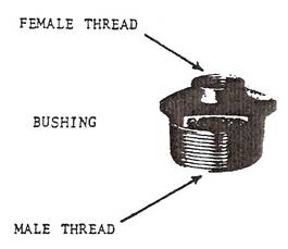
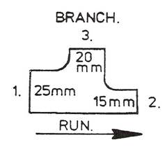
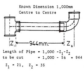
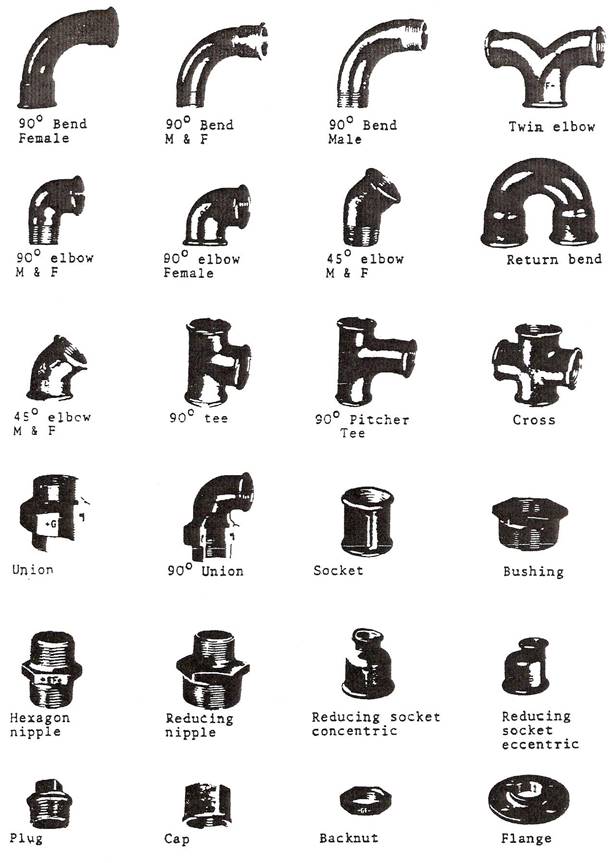
Figure 3 - Mild Steel Pipe Identification 1
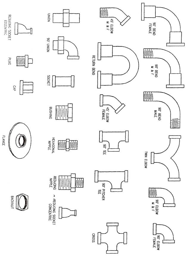
Figure 4 - Mild Steel Pipe Identification 2
Mild steel piping is supplied in 6.4m lengths.
Finished in Black or hot dipped galvanised for extra corrosion resistance. These lengths can have either:
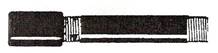
A. PLAIN ENDS: When they are to be welded together on site.
![]()
B. THREADED ENDS: When threaded joints are to be used on site. On threaded lengths, one socket is supplied with each length.
Mild steel pipes are sized by their internal diameters or bores and come in the following sizes, all in mm.
8, 10, 15, 20, 25, 32, 40, 50, 65, 80, 100, 150, 200 etc.
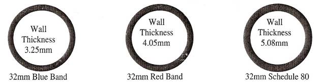
MEDIUM GRADE: Marked with blue band.
Suitable for low pressure hot water heating and gas installations.
HEAVY GRADE: Marked with a red band.
Suitable for steam and high temperature hot water heating installations.
SCHEDULE 40 & 80: The particular schedule is stamped on the outside of the pipe.
ACTUAL SIZE
Note: M.O.P No. = Maximum Operating Pressure.
Thread seals and taps are always applied in a clockwise direction when facing the threaded end of the pipe.
P.T.F.E TAPE:
Is suitable for oil and gas lines and oxygen and acetylene.
STAG JOINTING COMPOUND:
Is especially suitable for oil and gas lines.
The modern pipe fabrication shop requires that it be designed and organised to obtain a speedy flow of a large number of integral parts to finished complex assemblies. A typical fabrication shop is shown in Figure 5.
Figure 5 - General View of a Pipe Fabrication Shop
Prior to fabrication, workshop sketches or spools are prepared in the drawing office from either general arrangement drawings or isometrics. These sketches are simple and quickly prepared but are complete with all the necessary information to enable the pipes to be fabricated. The use of computerised isometrics is becoming widespread and is gradually replacing the hand-drawn isometric. The computerised isometric offers advantages to the pipework fabricator and some of these are:
These are highly important documents which are issued to the pipe fabricator's inspection department and to works' management and the standard laid down is strictly adhered to. Many purchasing companies issue their own standard specifications covering quality of workmanship and these all follow a similar pattern. The following typical specification gives an idea of the stringent control required during fabrication:
STANDARD SPECIFICATION No. SS-L5-1
FABRICATION OF PIPEWORK - CARBON STEEL AND CARBON ½ MOLY PIPEWORK TO USAS. B31.3
A. GENERAL
A.1. Purpose
The purpose of this standard specification is to define an acceptable standard for the fabrication of carbon steel and carbon ½ moly pipework to USAS B31.3, excluding large bore low pressure ducting and pipes to API 5LX specification.
Figure 6 - Pipebank being Hydraulic Tested in Test Bay
A good working knowledge is required of both subjects. Pipework in operation is always in movement and subjected to pressures and forces in itself with consequent reactions on mechanisms such as pumps, compressors and equipment generally and on structures, structural members and related pipework. Lack of knowledge can cause errors sufficient to cause machine or equipment breakdown, or to overstress and even cause collapse of structure.
Figure 7 - B.I.C.I.'s Olefines Plant at Wilton, Teeside
Capacity 450,000 tons of ethylene per year – the largest stream olefines plant in the world.
Figure 8 - Plate C. A Section of I.C.I.'s Olefines Plantat Wilton, Teeside
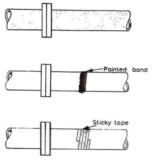 British Standard 1710: 1971, which agrees with I.S.0./R 508, lays down the colour coding used to denote the contents of pipes. The use of a system of colour coding is most important as it enables the fitter to immediately locate a pipe carrying a particular service. The colour coding can appear on the pipes in one of the following three ways:
The table below gives the colour codes used for denoting the different contents of pipes:
Colour |
Contents |
Green |
Water |
Silver grey |
Steam |
Brown |
Mineral, vegetable and animal oils, combustible liquids |
Yellow ochre |
Gases in liquid or gaseous form (except air) |
Light blue |
Air |
Violet |
Acids and Alkalis |
Black |
Other fluids |
Orange |
Electrical services |
The effect that an increase of carbon would have on steel should be noted. As the percentage of carbon is increased, so is the tensile strength, toughness and hardness of the steel, but it also reduces ductility.
In the heat-treatment processes the percentage of carbon present in a stool is one of the important factors in determining the required process temperature and the resulting properties of the steel.
For hardening, the temperature to which the steel should be heated varies according to the percentage of carbon present in the steel.
From pure iron which contains no carbon to steel containing 0.87% carbon this temperature decreases relatively slowly from approximately 950°C to 750°C.
The temperature rises steeply with an increasing carbon content above 0.87%, with an increased danger of brittleness and cracking.
Steels containing less than 0·3 % carbon cannot be hardened effectively, the maximum effect being obtained in steels having about 0.7% carbon content.
Tempering is usually only carried out on high-carbon steels which have been subjected to a hardening process.
Low-carbon steels are not easily hardened and therefore tempering is not required.
Carbon steels are classified according to the percentage of carbon they contain. They are referred to as low, medium, high and very-high-carbon steels.
Steels with a carbon range of 0.05 to 0.30 percent are called low-carbon steels. Steels in this class are tough, ductile and easily machined, formed and welded. Most of them do not respond to any heat treating process except case hardening. Low-carbon steel, when subjected to the spark test, will throw off long, white-coloured streamers with very little or no sparklers.
These steels have a carbon range from 0.30 to 0.45 percent. They are strong and hard but cannot be worked or welded as easily as low carbon steels. Because of their higher carbon content, they can be heat treated.
Steels with a carbon range of 0.45% to 0.75% are classified as high-carbon and those with 0.75% to 1.7% carbon as very-high-carbon steels. Both of these steels respond well to heat treatment. As a rule, steels up to 0.65% carbon can be welded with special electrodes, although preheating and stress relieving techniques must often be used after the welding is completed.
Carbon is the principal element controlling the structure and properties that might be expected from any carbon steel. The influence that carbon has in strengthening and hardening steel is dependent upon the amount of carbon present and upon its microstructure. Slowly cooled carbon steels have a relatively soft iron pearlitic microstructure; whereas rapidly quenched carbon steels have a strong, hard, brittle, martensitic microstructure.
When a metal is cold-worked (that is; hammered, rolled or drawn through a die) the ferrite and pearlite grains are made smaller and the metal becomes stronger and harder. If, after cold working, the metal is heated and allowed, to cool, the grain size is again increased and the metal softened.
Source: http://local.ecollege.ie/Content/APPRENTICE/liu/metalfab_notes/module5/Introduction%20to%20Pipes%20and%20Tubes_M5_U1.doc
Web site to visit: http://local.ecollege.ie/
Author of the text: indicated on the source document of the above text
If you are the author of the text above and you not agree to share your knowledge for teaching, research, scholarship (for fair use as indicated in the United States copyrigh low) please send us an e-mail and we will remove your text quickly. Fair use is a limitation and exception to the exclusive right granted by copyright law to the author of a creative work. In United States copyright law, fair use is a doctrine that permits limited use of copyrighted material without acquiring permission from the rights holders. Examples of fair use include commentary, search engines, criticism, news reporting, research, teaching, library archiving and scholarship. It provides for the legal, unlicensed citation or incorporation of copyrighted material in another author's work under a four-factor balancing test. (source: http://en.wikipedia.org/wiki/Fair_use)
The information of medicine and health contained in the site are of a general nature and purpose which is purely informative and for this reason may not replace in any case, the council of a doctor or a qualified entity legally to the profession.
The texts are the property of their respective authors and we thank them for giving us the opportunity to share for free to students, teachers and users of the Web their texts will used only for illustrative educational and scientific purposes only.
All the information in our site are given for nonprofit educational purposes