The first three states of matter are solid, liquid and gas. For the most commonly known substance, water, these states are ice, water and steam. If you add heat energy, the ice will change from a solid to a liquid, and if more heat is added, it will change to a gas (steam). When substantial heat is added to a gas, it will change from gas to plasma, the fourth state of matter.
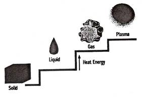
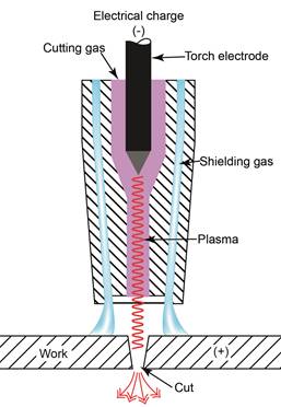
Figure 2 - Plasma - The Fourth State of Matter
Plasma is an electrically conductive gas. The ionisation of gases causes the creation of free electrons and positive ions among the gas atoms. When this occurs, the gas becomes electrically conductive with current carrying capabilities. Thus, it becomes a plasma.
One example of plasma, as seen in nature, is lightning. Just like a plasma torch, the lightning moves electricity from one place to another.
In lightning, gases in the air are the ionisation gases.
Accurate cuts can be made in stainless steel and non-ferrous metals such as aluminium by plasma arc cutting.
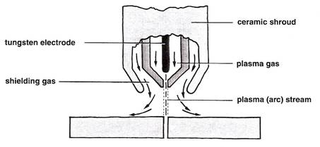
The cuts are made by a high temperature, high velocity gas jet generated by constricting an arc between a tungsten electrode and the component.
The heat from the arc melts the metal and the gas jet removes the molten metal from the cut.
The arc operates in an inert inner shield, whilst an outer shield provides protection for the cut surface.
Argon, helium, nitrogen and mixtures of these gases are used for both the inner and outer shields.
Plasma arc cutting is characterised by fast cutting speeds and is mainly used in mechanised systems.
The cutting is accompanied by a high noise level which can be reduced by operating the torch under water.
Plasma Arc Cutting
As for other arc processes plus there is a danger of severe electric shock from the high open circuit voltage, up to 400 V for cutting. Dangerous fumes and noxious gases are formed when using nitrogen mixtures so it is important to have adequate fume extraction. The intense arc requires a darker shade of filter glass, at least 16 EW (BS 697). Intense high-frequency noise is possible when cutting, especially with non-transferred arcs, of levels 110 dB which requires ear muff protection.
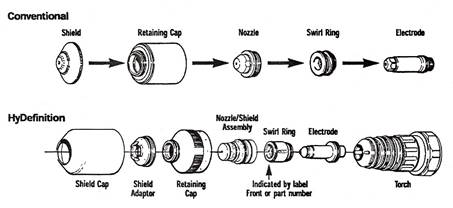
Component parts of a Plasma Arc Torch
C.W. = Cooling water, nozzle and electrode may be water cooled
P = Plasma gas varies with different materials.
S.G. = Auxiliary shielding gas, usually Argon + 1 to 15% H2
T.E. = Tungsten electrode 60°
O.S.R. = Outer shielding ceramic to prevent double arcing
R = Resistance limiting pilot arc current (non-transferred)
E.S.B. = Electrode set back distance
N.C. = Nozzle constriction
C.O. = Orifice constriction improves velocity
2.5 mm dia., 250 amps max.,
3.00 mm dia., 350 amps max.
S.0. = Stand-off distance approx. 6mm
M.P. = Multi-ports shape the arc plasma and allow increased welding speed
H.F. = High-frequency discharge ignites the arc
N. = Copper Nozzle
Consumable Usage Log |
|||||||
Starts |
Arc Time |
Errors |
Material Cut |
Current/Process |
Consumable Part |
Notes |
|
Start |
End |
||||||
|
|
|
|
|
|
|
|
|
|
|
|
|
|
|
|
|
|
|
|
|
|
|
|
|
|
|
|
|
|
|
|
|
|
|
|
|
|
|
|
|
|
|
|
|
|
|
|
Consumable Usage Log
Functions of gas in Plasma Arc cutting
Plasma gas is also called the cutting gas. This is the gas that is ionised in the plasma process and exits through the nozzle orifice.
Examples of plasma gas are:
The shield is the secondary gas in the plasma process. It surrounds the arc and is used to help constrict the arc and cool torch. It creates and protects the cutting environment which among other things affects the edge quality.
Examples of shielding gas are:
The cutting gas selected depends on the speeds and quality of cut desired. Several cutting gases can be used in a plasma system to improve cut quality and speed. Nitrogen is widely used because it is relatively inexpensive and can be used on many materials and thicknesses. Special mixtures of argon and hydrogen can improve cutting speed and quality on thicker metals and those other than carbon steels. Oxygen is used in combination with other gases to improve cut quality by increasing heat, improving cutting speed, and/or reducing power requirements. Compressed shop air is popular for many applications because it is inexpensive and provides good quality cuts on thicknesses under 25mm, especially on carbon steels.
Gas quality is critical for the proper operation of plasma arc cutting systems and optimal cut quality. Any contaminates can cause misfiring, poor cut quality or poor consumable life. Contaminates can be: gas impurities, moisture, dirt, piping system contaminates or improper gases (i.e. Air in O2 systems-leaks, not following proper purge procedures when changing gas).
The table below gives a list of the typical gases used for Plasma Arc cutting and the application that they are suitable for:
Gas Selection Chart |
|||
System |
Material |
Plasma Gas |
Shield Gas |
HyDefinition |
Mild Steel |
O2 |
O2 & N2 |
Stainless Steel- |
Air |
Air |
|
Air |
Air & Methane |
||
H35 & N2 |
N2 |
||
Aluminium |
Air |
CH4 |
|
H35 & N2 |
N2 |
||
Copper |
O2 |
O2 & N2 |
|
MAX200 & HT2000 |
Mild Steel |
O2 |
Air |
Stainless Steel |
Air |
Air |
|
H35 |
N2 |
||
Aluminium |
Air |
Air |
|
Copper |
O2 |
Air |
|
HT4001 |
Mild Steel ** |
O2 |
H2O |
Stainless Steel |
N2 |
H2O |
|
Aluminium |
N2 |
H2O |
|
*Only valid if equipped with six channel gas console (p/n: 078059 & 078061). |
|||
Gas Selection Chart
Aluminium and stainless steels require non-oxidising gases for good cutting results in both thin and thick sections. Argon/hydrogen mixtures permit good cuts and high cutting rates because the hydrogen increases the arc voltage and thermal conductivity of the mixture. Parallel kerfs, little dross, oxide-free cut faces and minimal fumes result from the use of A/H2 mixtures. Argon/Hydrogen/Nitrogen or A/N2 mixtures are used when machine cutting, but nitrogen is not recommended for hand cutting due to the formation of poisonous oxides of nitrogen. Higher cutting speeds are possible with this cheaper mixture with little loss of quality. The increase in cutting efficiency is probably derived from the greater anodic voltage drop associated with the nitrogen gas.
When inert gases such as argon are used, the heat is derived from the electrical energy of the arc. Carbon steels require an oxidising gas for the best results; the exothermic iron-oxygen reaction provides additional heat at the cutting point and so reduces the amount of electric power required. Air has proved to be a most efficient gas.
This should be as high as possible for economic reasons provided a narrow kerf and a clean cut at top and bottom edges are produced. For a given electric power and gas mixture, there is an optimum speed range for each type and thickness of material. Excess speed causes a decreased kerf width with an increased bevel but current intensity is the main factor determining kerf width. For manual control and complicated machine cuts 1 m/min is a reasonable speed. In general speeds of several metres/min are used for straight line and trimming cuts.
Material |
Thickness mm |
Current amps |
Cutting speed |
Gas |
Aluminium |
1.5 |
40 |
1200 |
A/H2 |
Stainless steel 18/8 |
2 |
50 |
1600 |
A/H2 |
Variation of Cutting Speed with Typical Gas-type and Current
Plasma cutting power sources are rated on their cutting ability and amperage. Therefore, for cut depths up to 6mm thick material, a low amperage plasma cutter will suffice. For cut depths up to 12mm thick a higher amperage machine will be required. Even though a smaller machine may be able to cut through a given thickness of metal, it may not produce a quality cut. Instead, you may get a sever cut which barely makes it through the plate and leaves behind dross or slag. Every unit has an optimal range of thickness -- make sure it matches up with what you need. In general, a 6mm machine has approximately 25 amps of output, a 12mm machine has a 50-60 amp output while a 18mm to 25mm machine has 80 amps output. The table below gives typical piercing and cutting depths for different materials
System |
Material Type |
Max Cut Capacity |
Max Pierce Capacity |
HD3070 |
Mild Steel |
6mm |
6mm |
Stainless Steel |
6mm |
6mm |
|
Aluminium |
6mm |
6mm |
|
MAX200 |
Mild Steel |
50mm |
25mm |
Stainless Steel |
50mm |
22mm |
|
Aluminium |
50mm |
22mm |
|
HT2000 |
Mild Steel |
50mm |
25mm |
Stainless Steel |
50mm |
22mm |
|
Aluminium |
50mm |
22mm |
|
HT4001 |
Mild Steel w/O2 |
30mm |
25mm |
Mild Steel w/N2 |
75mm |
25mm |
|
Stainless Steel |
75mm |
25mm |
Cutting depths with Plasma
The safety precautions to be observed for Plasma Arc cutting are similar for other thermal processes with following clarifications:
Explosion Hazard: Argon-Hydrogen and Methane
Hydrogen Detonation with Aluminium Cutting
Touching live electrical parts can cause a fatal shock or severe burn.
Electric Shock Prevention
Plasma systems use high voltage in the cutting process (200 to 400 VDC are common). Take the following precautions when operating these systems:
Cutting can produce toxic fumes and gases that deplete oxygen and cause injury or death.
Plasma arc comes on immediately when the torch switch is activated. The plasma arc will cut quickly through gloves and skin.
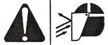
Eye Protection Plasma arc rays produce intense visible and invisible (ultraviolet and infrared) rays that can bum eyes and skin.
Arc Current |
Lens Shade |
|
|
AWS (USA) |
ISO 4850 |
||
Up to 100 A |
No. 8 |
No. 11 |
|
100-200 A |
No. 10 |
No. 11-12 |
|
200-400 A |
No. 12 |
No. 13 |
|
Over 400 A |
No. 14 |
No. 14 |
|
Work Cable
Attach the work cable securely to the workpiece or the work table with good metal-to-metal contact. Do not connect it to the piece that will fall away when the cut is complete.
Work Table
Connect the work table to an earth ground, in accordance with appropriate national or local electrical codes.
Input Power
Gas Cylinders Can Explode If Damaged
Gas cylinders contain gas under high pressure. If damaged, a cylinder can explode.
Prolonged exposure to noise from cutting or gouging can damage hearing.
Pacemaker and hearing aid operation can be affected by magnetic fields from high currents. Pacemaker and hearing aid wearers should consult a doctor before going near any plasma arc cutting and gouging operations.
To reduce magnetic field hazards:
The following are generic instructions for the setting up of a Plasma Arc cutting equipment. As there are many different suppliers of Plasma Arc cutting equipment is not possible to provide a specific check list.
Equipment, particularly composite power sources, varies considerably in their control arrangements and therefore it is important to verify that actual equipment used is set-up correctly.
Always -
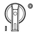
Position the power switch to ON (I) as shown.
Check that the Gas Pressure LED is illuminated in Green.

Check that the remaining indicator lamps are NOT illuminated.
Set pressure: Cutting – 70-75 psig (4.8-5.2 bar), Gouging – 50-60 psig (3.4-4.1 bar)
Push regular knob to lock
|
WARNING |
Plasma arc comes on immediately when the torch switch is activated.
|
|
Safety Trigger Operation:
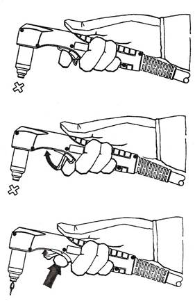
1.
2.
3.
|
WARNING |
When firing the torch at an angle, sparks and hot metal will spray out from the nozzle. Point the torch away from yourself and others. |
|
Attach the work clamp securely to the workpiece. Remove rust, paint or other coatings to ensure good electrical contact.
Attach the work clamp as close as possible to the area being cut, to reduce exposure to electromagnetic fields (EMF).
Do not attach the work clamp to the portion that will fall away.
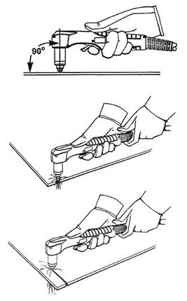
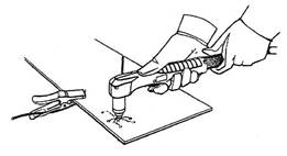
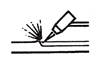
Hold the torch nozzle vertical at the edge of the workpiece.
Start cutting from the edge of the workpiece. Pause at the edge until the arc has completely cut through the workpiece.
Then, proceed with the cut.
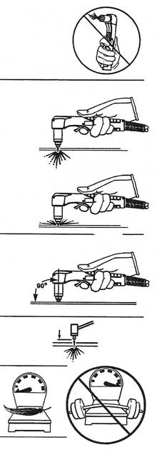
Firing the torch unnecessarily reduces nozzle and electrode life.
When cutting, make sure that sparks are exiting from the bottom of the workpiece.
If the sparks are spraying up from the workpiece, you are moving the torch too fast, or without sufficient power.
Position the torch nozzle at a vertical position and watch the arc as it cuts along the line.
Unshielded Consumables. Maintain an approximate ⅛ inch (3 mm) torch-to-work distance.
Shielded Consumables. Do not push down on the torch when cutting. Lightly drag the torch across the workpiece to maintain a steady cut.

 |
WARNING |
When firing the torch at an angle, sparks and hot metal will spray out from the nozzle. Point the torch away from yourself and others. |
|
Hold the torch so that the nozzle is within ⅛ inch (3 mm) from the workpiece before firing the torch.
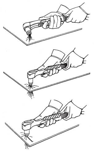
Fire the torch at an angle to the workpiece, and then slowly rotate it to an upright position.
When sparks are exiting from the bottom of the workpiece, the arc has pierced through the material.
When the pierce is complete, proceed with the cut.
|
WARNING |
When firing the torch at an angle, sparks and hot metal will spray out from the nozzle. Point the torch away from yourself and others. |
|
Hold the torch so that the nozzle is within 1.5 mm from the workpiece before firing the torch.
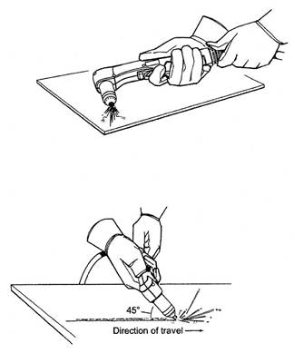
Hold the torch at a 45 degree angle to the work piece. Pull the trigger to obtain a pilot arc. Transfer the arc to the work piece.
Maintain a 45° angle, approximately from the workpiece.
Feed into the gouge.
Note: A heat shield is available for added hand and torch protection.
Title |
Author |
Ref. Code |
The Induction Book, “Code of Behaviour & Health & Safety Guidelines” |
SOLAS |
|
Basic Welding and Fabrication |
W Kenyon |
ISBN 0-582-00536-L |
Fundamentals of Fabrication and Welding Engineering |
FJM Smith |
ISBN 0-582-09799-1 |
Workshop processes, practices and materials, 3rd edition, Elsevier Science & Technology |
Black, Bruce J 2004 |
ISBN-13: 9780750660730 |
New Engineering Technology |
Lawrence Smyth & Liam Hennessy |
ISBN 086 1674480 |
Source:
Web site to visit:
Author of the text: indicated on the source document of the above text
If you are the author of the text above and you not agree to share your knowledge for teaching, research, scholarship (for fair use as indicated in the United States copyrigh low) please send us an e-mail and we will remove your text quickly. Fair use is a limitation and exception to the exclusive right granted by copyright law to the author of a creative work. In United States copyright law, fair use is a doctrine that permits limited use of copyrighted material without acquiring permission from the rights holders. Examples of fair use include commentary, search engines, criticism, news reporting, research, teaching, library archiving and scholarship. It provides for the legal, unlicensed citation or incorporation of copyrighted material in another author's work under a four-factor balancing test. (source: http://en.wikipedia.org/wiki/Fair_use)
The information of medicine and health contained in the site are of a general nature and purpose which is purely informative and for this reason may not replace in any case, the council of a doctor or a qualified entity legally to the profession.
The texts are the property of their respective authors and we thank them for giving us the opportunity to share for free to students, teachers and users of the Web their texts will used only for illustrative educational and scientific purposes only.
All the information in our site are given for nonprofit educational purposes