
Pneumatic systems make use of compressed air. Compressed air is quite simply the air that we breathe forced or squashed into a smaller space. We can use the energy stored in this compressed air to do things.
There are usually lots of different ways to carry out a task, so it is important to understand some of the reasons for choosing pneumatic systems.
Pneumatic systems are clean because they use compressed air. We know already that this is just the air we breathe forced into small spaces. If a pneumatic system develops a leak, it will be air that escapes and not oil. This air will not drip or cause a mess and this makes pneumatics suitable for food production lines.
Pneumatic systems are very safe compared to other systems. We cannot, for example, use electronics for paint spraying because many electronic components produce sparks and this could cause the paint to catch fire.
It is important, however, that we look after and maintain the different components. It is also important that we follow the correct safety rules.
Pneumatic systems are very reliable and can keep working for a long time. Many companies invest in pneumatics because they know they will not have a lot of breakdowns and that the equipment will last for a long time.
If we compare pneumatic systems to other systems, we find that they are cheaper to run. This is because the components last for a long time and because we are using compressed air. Many factories already have compressed air for other reasons.
Once you have bought the basic components, you can set them up to carry out different tasks. Pneumatic systems are easy to install and they do not need to be insulated or protected like electronic systems.
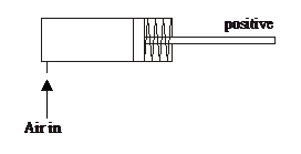
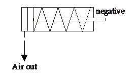
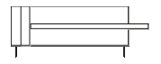
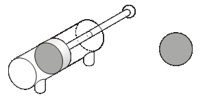
A single-acting cylinder requires only one air supply. If we supply compressed air to a single-acting cylinder, the air pushes against the piston inside the cylinder and causes it to outstroke. When the piston has fully outstroked it is said to be positive.
If we stop the supply of air then the spring inside the cylinder causes the piston to instroke to its starting position and the piston is said to be negative. As this happens, the air inside the cylinder is pushed back out.
![]()
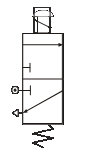
The symbol for a single-acting cylinder is shown right.
Single-acting cylinders are easy to use and control but they do not produce very big forces. This means that we need to be careful of what we use them for.
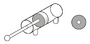
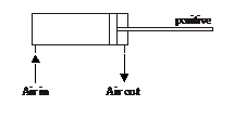 A double-acting cylinder has no spring inside to return it to its original position. It needs two air supplies, one to outstroke the piston and the other to instroke the piston.
To outstroke a double-acting cylinder we need compressed air to push against the piston inside the cylinder. As this happens, any air on the other side of the piston is forced out. This causes the double-acting cylinder to outstroke. When the piston has fully outstroked it is said to be positive.
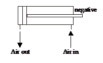
To instroke a double-acting cylinder we need to reverse this action. We supply the compressed air to the other side of the piston. As the air pushes the piston back to its original position, any air on the other side is again forced out. This causes the piston to instroke and it is said to be negative.
The symbol for a double-acting cylinder is shown right.
 Valves
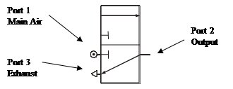
A 3/2 valve gets its name because it has three ports and two states. One state prevents air from being supplied to other components and the other allows the air to flow freely.
Port 1 – Main air. Remember that our main air is supplied through a manifold.
This port lets us make connections to other components. Remember, the purpose of valves is to control the flow of air to other components, usually cylinders.
This port allows air trapped in the circuit to escape or exhaust. Remember, for our cylinders to instroke and outstroke, they need the air on the other side of the piston to escape.
 Actuators
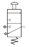
 There are a number of different ways that we can operate a 3/2 valve. The most common way is by using a push button. By pressing the button, the valve changes to the actuated state and allows main air to flow through to other components. If we release the button, a spring inside returns the valve to its off state. The symbol for a push button, spring return 3/2 valve is shown right.
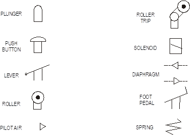
Below is a list of the most common types of actuators. They are always drawn onto the standard symbol for the 3/2 valve.
A T-piece or T-connector is a very simple component that lets us split or divide airflow. It can be very useful if you want two cylinders to operate at the same time.
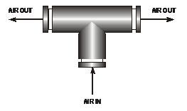
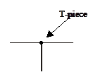
On circuit diagrams, the
T-piece is identified by a dot.
5/2 valves
There are many problems when controlling a double-acting cylinder with two 3/2 valves. When you actuate the 3/2 valve, it outstrokes the piston. When the 3/2 valve is not actuated, air is free to escape or exhaust back through the valve. This means that any force or effort placed on the piston will make it move easily.
A further disadvantage is that the 3/2 valve needs to be actuated until the double-acting cylinder has fully outstroked or instroked. Releasing the valve before the stroke is complete will mean the piston will stop short of its final position.
We have greater control over a double-acting cylinder if we control its outstroke and instroke using a 5/2 valve. This valve has five ports and two states of operation. The ports are always numbered in the same way.
This port is connected to main air just like a 3/2 valve.
This port is usually connected to instroke a double-acting cylinder.
This port allows air trapped in the double-acting cylinder to escape. Remember, for the cylinder to instroke and outstroke, air on the other side of the piston must be allowed to escape. If this did not happen, the piston would not move.
This port is usually connected to outstroke a double-acting cylinder.
Again, this port lets the air on the other side of the piston escape.
5/2 valves can be operated or actuated in the same way as 3/2 valves. However, the most common way of actuating a 5/2 valve is by pilot air. A pilot air 5/2 valve will change state when a brief air signal acts at either end of the valve. This signal is most often supplied from a 3/2 valve. In the example shown below, the button on ‘valve A’ only needs to be pressed for a moment in order to change the state of the 5/2 valve. The 5/2 valve supplies the double-acting cylinder with air to make it outstroke.
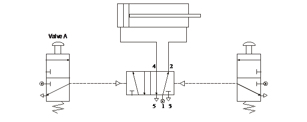
Notice that the pilot airlines to the 5/2 valve are drawn as broken or dashed lines to distinguish them from the other air lines in the circuit.
To slow down the speed of a piston we use a flow control valve.
Restrictor
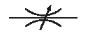 There are two types of flow control valve available to us. The first type is called a restrictor (or sometimes a throttle valve). This valve works by reducing the amount of space that the air can flow through. We can adjust the airflow by turning the small screw on top of the valve. The symbol for a restrictor is shown right.
This restrictor slows down the flow of air in both directions. This means that using only one extra component can slow both the outstroke and instroke of a cylinder.
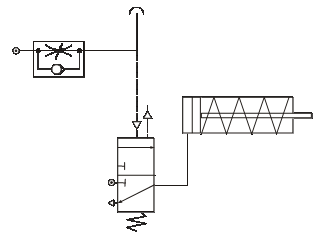
In the circuit shown below, the restrictor is used to slow down the speed of the single-acting cylinder. We can adjust this speed by turning the small screw on the top of the restrictor.
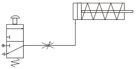
The problem with this type of restrictor is that it always slows down the speed of the piston in both directions. In many cases, we would only want either the outstroke or the instroke to be slowed down. Also, if we study the piston movement very carefully, we sometimes find that it is quite jerky - not smooth as we would want it to be.
Unidirectional Restrictor
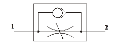
To solve these problems we can use a component called a unidirectional restrictor. As its name suggests, it only slows down the air in one direction. The symbol is shown right.
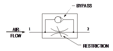
When air flows into port 1 of the restrictor, some of the air takes the bypass route. A small ball is blown against a valve and blocks this path. The air is then forced to go through the restriction and this slows down the airflow.
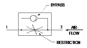 When air flows into port 2 of the restrictor, again some of the air takes the bypass route. This time, the ball is blown away from the valve and the air passes through unrestricted.
In pneumatics, unidirectional restrictors are much more useful to us. However, we must always be careful to insert them in the circuit the correct way round.
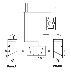 Study the circuit (right) and take note of the position of the unidirectional restrictor. Is it where you expected? The restrictor is placed so that it slows down the exhaust air coming from the cylinder. When ‘valve A’ is pressed, the 5/2 valve changes state and starts to supply the cylinder with air to make it outstroke. Air trapped on the other side of the piston escapes through the restrictor slowly. This makes the piston outstroke slowly.
 AND Control
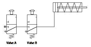
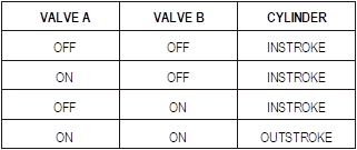
This involves connecting 3/2 valves together in series. This means that the output from one valve becomes the input to another. Study the diagram left and the truth table below.
 Sometimes we need to control a pneumatic circuit from more than one position. This can be done using OR control circuits. These circuits are quite simple but they need another component called a shuttle valve.
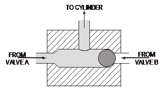
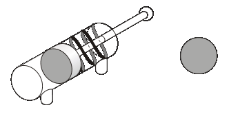
A shuttle valve is used to change the direction of air in a circuit. It has a small ball inside that gets blown from side to side. A picture is shown below.
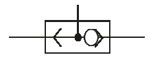 When air is supplied from valve A, the ball gets blown across and the air is directed towards the cylinder. When air is supplied from valve B, the ball is blown to the other side and again the air flows into the cylinder. If air comes from both directions, air still manages to reach the cylinder, as this is the only path it can take. The symbol for a shuttle valve is shown right.
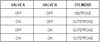
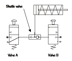 OR control involves connecting 3/2 valves together in parallel. This means that either valve will outstroke the cylinder. Study the diagram left and the truth table below.
 Time Delay
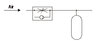
 Sometimes in a circuit we want a pause or delay before something else happens. To create a delay we need to use two components – a unidirectional restrictor and a reservoir.
A reservoir is simply an empty container, just like an empty bottle. The bigger the reservoir, the longer it takes to fill up with air. To make the delay longer we use a unidirectional restrictor in front of the reservoir. This slows down the air so that the reservoir takes even longer to fill. The length of time it takes to fill creates the delay.
We can change the length of a delay by changing the size of the reservoir or adjusting the restrictor.
 Air Bleed
 Sometimes with pneumatics we find that the actuators on valves can get in the way of the circuit. Also, some actuators need a big force to make them work and this is not always possible. There are different ways to overcome these problems and one of the most common is to use an air bleed.
An air bleed is simply an open pipe that allows the air in the circuit to escape. This air must be at a low pressure, otherwise the pipe would ‘wave’ about and be dangerous. Air bleed circuits rely on a component called a diaphragm valve. This valve is capable of detecting small changes in air pressure. The valve works in the same way as other 3/2 valves; it is only the actuator that is new to us. The symbol is shown below.
The diaphragm is a piece of rubber stretched inside the valve. When air flows into the top of the valve, the rubber expands much in the same way as when a balloon is blown up. When the diaphragm expands, it presses down inside the valve and changes its state.
The signal to the diaphragm comes from an air bleed. When the air bleed is blocked, air is diverted back towards the diaphragm. This actuates the 3/2 valve and the cylinder outstrokes. Notice that the airflow to the air bleed passes through a restrictor. This slows down the air before it is allowed to escape.
 Sequential Control
Many pneumatic systems and machines are designed to perform a range of tasks in a certain order or sequence. This usually involves the use of two or more cylinders working together to complete the task.
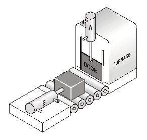
For example, a company has automated its production line that involves metal blocks being placed in a furnace for heat treatment. One cylinder is used to open the furnace door and another pushes the metal blocks into the furnace.
The sequence of operations for this process is as follows.
 For this system to work successfully, we need to fully understand the order and movement of cylinders A and B.
Stage 1 - Cylinder A instrokes to raise the furnace door.
Stage 2 - Cylinder B outstrokes and pushes the metal block into the furnace.
Stage 3 - Cylinder B instrokes.
Stage 4 - Cylinder A outstrokes and closes the furnace door.
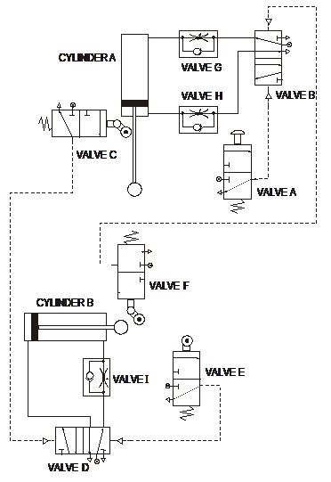
The pneumatic circuit that carries out this operation is shown right.
The system begins by actuating valve A. This changes the state of valve B and causes cylinder A to instroke, raising the door. When fully instroked, or negative, the piston trips valve C and this sends a signal to valve D. This 5/2 valve changes state and sends cylinder B positive. When fully outstroked, the piston trips valve E and the cylinder instrokes. When negative, valve F is actuated and causes cylinder A to outstroke and stay in the positive position. The system stops and waits for a signal from valve A.
We can summarise the sequence of this circuit as follows.
Start, A-, B+, B-, A+, Stop
Forces in a single-acting cylinder
When a single-acting cylinder outstrokes, it produces a force. The size of the force produced by the cylinder as it outstrokes depends on two things - the air pressure supplied to the cylinder and the surface area of the piston. This means that if we want a bigger force we can either use a larger piston or increase the air pressure. However, it is not a good idea to increase the air pressure because this can damage components.
Pressure
Air pressure is measured in bars or in N/mm2 (newtons per square millimetre).
Whenever we use pressure in calculations, we require the units to be in N/mm2. This sometimes means converting from bars to N/mm2. This conversion is easy, as you simply divide the value in bars by 10. For example, if the pressure supplied to a system is 5 bars, we can find the equivalent value in N/mm2 by simply dividing 5 by 10. Therefore, the value would be 0.5 N/mm2.
 Area
AreaThe surface area of the piston is the area that the air pushes against to outstroke the piston. This area is circular.
The area of a circle is calculated using the formula,
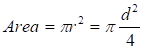
where r is the radius and d is the diameter of the circle.
The force produced when a single-acting cylinder outstrokes is calculated using the formula:
Force = Pressure ´ Area
where force is measured in newtons (N), pressure is measured in N/mm2 and area is measured
in mm2.

 In some situations, we would know the size of the force needed to do a job properly. In this case, we would want to calculate the pressure needed or the size of the piston. To do this we need to rearrange our formula.
Air is supplied to a single-acting cylinder at a pressure of 4 N/mm2. The diameter of the piston is 25 mm. Calculate the force produced as the piston outstrokes.
Write down any information that you have from the question.
Pressure = 4 N/mm2
Diameter = 25 mm
We need to calculate the surface area.
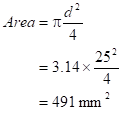
Use the correct formula for what you are trying to find. In this case, calculate the force.
Force = Pressure ´ Area
= 4 ´ 491
= 1964 N
We already know that a double-acting cylinder can be much more useful to us in pneumatics because both the outstroke and instroke are controlled by compressed air. This allows us to make use of both the outstroke and the instroke force. What we learn, however, is that the outstroke force is greater than the instroke force. Why is this the case?
 During the outstroke, the compressed air pushes against the surface area of the piston in the same way as in the single-acting cylinder.
However, during the instroke the surface area is reduced because of the piston rod. This means that the compressed air does not have as big an area to push against and so it does not produce as big a force.
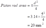
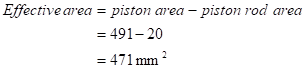
We can find this surface area, or effective area as it is known, by calculating the area of the piston rod and subtracting it from the surface area of the piston.
Effective area = piston area – piston rod area
A double-acting cylinder has a piston with a diameter of 25 mm. The piston rod is
5 mm in diameter. Pressure is supplied to the system at 4 N/mm2. Calculate the force produced by the cylinder as it outstrokes and instrokes.
Write down any information that you have from the question.
Pressure = 4 N/mm2
Piston diameter = 25 mm
Piston rod diameter = 5 mm
We need to calculate the surface area.

Use the correct formula for what you are trying to find. In this case, calculate the outstroke force.
Force = Pressure ´ Area
= 4 ´ 491
= 1964 N
Outstroke force = 1.96 kN
Calculate the piston rod area.
Calculate the effective area. (We already know the piston area from step 2.)
Calculate the instroke force.
Force = Pressure ´ Effective Area
= 4 ´ 471
= 1884 N
Electronic Control of Pneumatics
 There are many advantages in controlling pneumatic circuits with electronics. First, electronic signals are faster than pneumatic signals, so circuits respond much more quickly. We can also carry electrical signals over longer distances than pneumatic signals. Finally, electronic components are much smaller than pneumatic actuators, which can be bulky and interfere with the operation of a circuit.
If we control pneumatic circuits with electronics we can design complicated control systems and still use pneumatic components for lifting and moving and all the things that they do best.
To control a pneumatic circuit with electronics we need to use a solenoid-operated valve.
 This type of valve works in the same way as other 3/2 or 5/2 valves with the exception that it is actuated by an electrical signal. This electrical signal can be produced by many different components such as microswitches and reed switches. Reed switches are useful if the cylinder has a magnetic piston band. This means that you can detect the position of the piston without relying on a switch or button that needed to be pressed.
Most solenoids are 8 V or 12 V devices. The voltage rating will be stamped or printed onto the solenoid casing. You must always check this before you start work with solenoids.
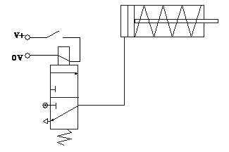
The circuit diagram would look like this:
To get the single-acting cylinder to outstroke, you press the microswitch. This energises the solenoid valve and it changes state. The valve then allows air to flow into the cylinder. Once the switch is released, the cylinder instrokes.
Source: http://www.earlstonhigh.scotborders.sch.uk/learningzone/technical/Revision%20Notes/SGTS%20Revision%20Notes/2-Pneumatics.doc
Web site to visit: http://www.earlstonhigh.scotborders.sch.uk/
Author of the text: indicated on the source document of the above text
If you are the author of the text above and you not agree to share your knowledge for teaching, research, scholarship (for fair use as indicated in the United States copyrigh low) please send us an e-mail and we will remove your text quickly. Fair use is a limitation and exception to the exclusive right granted by copyright law to the author of a creative work. In United States copyright law, fair use is a doctrine that permits limited use of copyrighted material without acquiring permission from the rights holders. Examples of fair use include commentary, search engines, criticism, news reporting, research, teaching, library archiving and scholarship. It provides for the legal, unlicensed citation or incorporation of copyrighted material in another author's work under a four-factor balancing test. (source: http://en.wikipedia.org/wiki/Fair_use)
The information of medicine and health contained in the site are of a general nature and purpose which is purely informative and for this reason may not replace in any case, the council of a doctor or a qualified entity legally to the profession.
The texts are the property of their respective authors and we thank them for giving us the opportunity to share for free to students, teachers and users of the Web their texts will used only for illustrative educational and scientific purposes only.
All the information in our site are given for nonprofit educational purposes