
Module 4: Polymer-EXTRUSION based Technologies
The two important polymer-extrusion based technologies that are mainly used to convert the molten polymer into nonwoven fabrics are spunbond technology and meltblown technology.
In the spunbond technology, usually a thermoplastic fibre forming polymer is extruded to form fine filaments fibres of around 15–35 micrometer diameter. The filaments are attenuated collected on a conveyor belt in the form of a web. The filaments in web are then bonded to make spunbond nonwoven fabric.
Raw materials
Spunbond technology uses preferably thermoplastic polymers with high molecular weight and broad molecular weight distribution such as polypropylene (PP) and polyester (PET) [1]. To a small extent, other polyolefins such as polyethylene of high density (HDPE) and linear polyethylene of low density (LLDPE) as well as a variety of polyamides (PA), mainly PA 6 and PA 6.6 are found. Out of these polymers, polypropylene is mostly used primarily due to its low price and advantageous properties such as low density, chemical resistance, hydrophobicity, sufficient or even better strength. The fibre grade polypropylene (mainly isotactic) is the principal type of polypropylene which is used in spunbond technology. The important raw material parameters for polypropylene to be a suitable candidate for spunbond technology are melt flow index (MFI) of about 20–40 g/10 min and polydispersity ratio (Mw/Mn) of around 3.5–7. The molecular weight can be around 180000. On the other hand, the important raw material parameters for polyester are intrinsic viscosity of about 0.64, low share in COOH-groups, high crystallinity, and low water content (as low as 0.004%). Spunbond nonwovens are exclusively made from crystalline polyester. Crystallinity influences pre-drying and extrudability as well as filament drawing orientation, which is basic to make products that meet the requirements and that are of proper strength. Pre-drying is inevitable as PET at thermal strain is subject to hydrolytic degradation when extruded. In addition, low water content avoids air pockets in the melt that might cause filament breakage. Frequently, requirements can only be met by means of polymer modification. Except for the mechanical properties, UV-resistance and flame-retardancy are important with technical applications.
Process sequence
Figure 4.1 displays a schematic diagram of spunbond machine. The spunbond technology, in its simplest form, consists of four processes namely, spinning, drawing, web formation, and web bonding. The spinning process largely corresponds to the manufacture of synthetic fibre materials by melt-spinning process. In the drawing process, the filaments are drawn in a tensionally locked way. The web formation process forms a nonwoven web. Web bonding is generally possible by means of the web bonding processes discussed earlier. The bonding process includes mainly thermal calender bonding. Mechanical bonding and chemical bonding of spunlaid webs are also reported. The sequence of processes is as 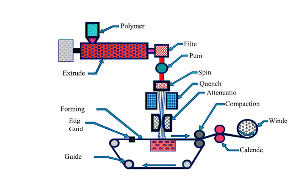 follows: polymer preparation --> polymer feeding, melting, transportation and filtration --> Extrusion --> Quenching --> Drawing --> Laydown --> Bonding --> Winding.
The first step to spunbond technology involves preparation of polymer. It involves sufficient drying of the polymer pellets or granules and adequate addition of stabilizers/additives. The drying of the polymer is carried out particularly for polyester and polyamides as they are relatively high hygroscopic than polypropylene. The stabilizers are often added to impart melt stability to the polymers. Then, the polymer pellets or granules are fed to an extruder hopper by gravity-feeding. The pellets are then supplied to an extruder screw, which rotates within the heated. As the pellets are conveyed forward along the hot walls of the barrel between the flights of the screw, the polymer moves along the barrel, it melts due to the heat and friction of the viscous flow and the mechanical action between the screw and barrel. The screw is divided into feed, transition, and metering zones. The feed zone preheats the polymer pellets in a deep screw channel and conveys them into the transition zone. The transition zone has a decreasing depth channel in order to compress and homogenize the melting plastic. The melted polymer is discharged to the metering zone, which serves to generate maximum pressure for pumping the molten polymer. The pressure of the molten polymer is highest at this point and is controlled by the breaker plate with a screen pack placed near the screw discharge. The screen pack and breaker plate also filter out dirt and unmelted polymer lumps. The pressurized molten polymer is then conveyed to the metering pump.
A positive displacement volume metering device is used for uniform melt delivery to the die assembly. It ensures the consistent flow of clean polymer mix under process variations in viscosity, pressure, and temperature. The metering pump also provides polymer metering and the required process pressure. The metering pump typically has two intermeshing, counter-rotating, toothed gears. The positive displacement is accomplished by filling each gear tooth with polymer on the suction side of the pump and carrying the polymer around to the pump discharge. The molten polymer from the gear pump goes to the feed distribution system to provide uniform flow to the die nosepiece in the die assembly.
The die assembly is one of the most important elements of the spunbond technology. The die assembly has two distinct components: the polymer feed distribution section and the spinneret.
The feed distribution in a spunbonding die is more critical than in a film or sheeting die for two reasons. First, the spunbonding die usually has no mechanical adjustments to compensate for variations in polymer flow across the die width. Second, the process is often operated at a temperature range where thermal breakdown of polymers proceeds rapidly. The feed distribution is usually designed in such a way that the polymer distribution is less dependent on the shear sensitivity of the polymer. This feature allows the processing of widely different polymeric materials using just one distribution system. The feed distribution balances both the flow and the residence time across the width of the die. There are basically two types of feed distribution that are employed in the spunbonding die, the T-type (tapered and untapered) and the coat-hanger type. An in-depth mathematical and design description of each type of feed distribution is given by Mastubara [2-5]. The T-type feed distribution is widely used because it gives both even polymer flow and even residence time across the full width of the die.
From the feed distribution channel the polymer melt goes directly to the spinneret. The spinneret is one of the components of the die assembly. The web uniformity partially hinges on the design and fabrication of the spinneret, therefore the spinneret in the spunbonding process requires very close tolerances, which has continued to make their fabrication very costly. A spinneret is made from a single block of metal having several thousand drilled orifices or holes. The orifices or holes are bored by mechanical drilling or electric discharge machining (EDM) in a certain pattern. The spinnerets are usually circular or rectangular in shape. In commercial spunbonding processes, the objective is usually to produce a wide web (of up to about 5 m), and therefore many spinnerets are placed side by side to generate sufficient fibers across the width.21 The grouping of spinnerets is often called a block or bank. In commercial production lines, two or more blocks are used in tandem in order to increase the coverage of the filaments.
The proper integration of filament spinning, drawing, and deposition is critical in the spunbonding process. The main collective function is to solidify, draw, and entangle the extruded filaments from the spinneret and deposit them onto an air-permeable conveyor belt or collector.
Filament drawing follows spinning. In conventional extrusion spinning, drawing is achieved using one or more set of draw rollers. While roller drawing can certainly be used in spunbonding, a specially designed aerodynamic device such as a Venturi tube is commonly adopted.
Filament deposition follows the drawing step. Filament deposition is also frequently achieved with the aid of a specially designed aerodynamic device referred to as a fanning or entangler unit. The fanning unit is intended to cross or translate adjacent filaments to increase cross-directional web
Production systems
The concept of spunbond technology was developed sometime in late 1950s simultaneously in Europe and USA. Since then numerous innovations are disclosed on spunbond production system. This technology is derived from filament spinning technology. Many patents were granted on filament spinning technology. The basic principles involved in it, as proposed by Hartman [6], are explained with the help of Figure 4.2.
Figure 4.2a illustrates a system of filament formation. Here air as hot as melting temperature emerges from closely to the nozzle holes, takes the filaments and draws them. The emerging air, at the same time, intermingles with the ambient air. It uses longitudinal spinnerets, with air slots on both sides for the expulsion of the drawing gas ‘1’ (primary air). The room air (secondary air) ‘2’ is carried along and after lay down of the filaments, the air is removed by suction ‘3’. This process is well suited for tacky polymers, such as linear polyurethene. The continuous filaments after web collection bond themselves (self-bond) at their crossover points due to their inherent tackiness. Crystallization, which then sets in, subsequently eliminates the stickiness of the filaments after bonding.
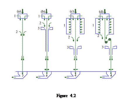 Figure 4.2b describes another system. Here the emerging air and the filaments are taken to a drawing channel. Blowing in additional pressed air the drawing effect can be realized. It uses higher draw ratio, which results in increased molecular orientation of filaments. Filaments are drawn with several air or gas streams using drawing conduits. The air is removed by suction ‘4’ after the web is formed.
Figure 4.2c depicts one more system. Here the cooling and drawing air are separated. It operates with regular cooling duct ‘1’ and drawing jet ‘3’. The drawing and cooling arrangements can be operated to give very high spinning speeds with the result that highly oriented filaments are produced. The room air ‘2’, of controlled temperature and moisture content, can be entrained to control the development of filament properties. The air is removed by suction ‘4’ after web formation.
Figure 4.2d illustrates another system that has a mechanical drawing step ‘2’ between the spinneret and lay down zones. This route is similar to conventional spinning and is especially useful for polymers, which in regular air drawing do not give optimum filament ‘4’. Webs with high strength and low elongation are generally made using this particular system.
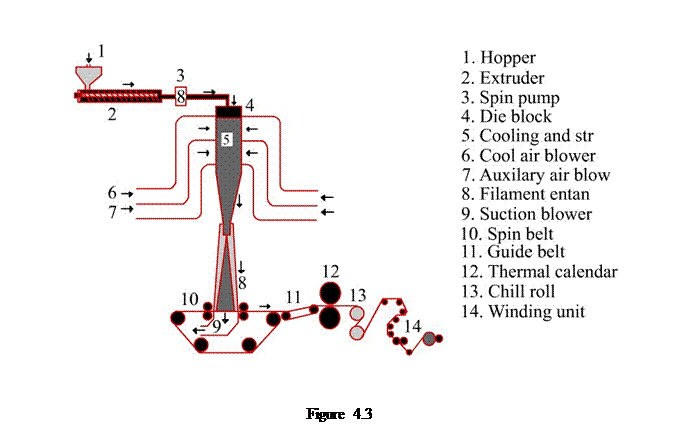
Some of the commercial spunbond production systems are Docan system, Lutravil system, Ason/Neumag system, Reicofil system and Rieter system. We will discuss one system, the interested readers can learn about other systems from [1]. Figure 4.3 displays the schematic diagram of Reicofil spunbond system. The polymer pellets or granules are vacuum fed to dosing station on top of the extruder. Inside the extruder the polymer pellets are melted and homogenised. The molten polymer is then passed through a filter system and a spin punp, the melt is distributed by a coathanger die, feeding the spinneret which forms a curtain of filaments. The filaments are cooled by means of a stream of air in a blowing area, drawn by aerodynamic forces and then transported to the downstream discharge channel. Here, the primary blow ducts, located below the spinneret block, continuously cool the filaments with conditioned air. The secondary blow ducts, located below the primary blow ducts, continuously supply the auxiliary air at room temperature. A ventilator operating across the width of the machine, generates under-pressure and sucks the filaments together with the mixed air down from the spinnerets and cooling chambers. The filaments are swirled around and then deposited on the wire mesh belt as a random nonwoven material. This is transferred to the heat bonding calender which by heat and pressure sets the physical properties as tensile and elongation of the final product. After calendering the material is cooled by a water-cooled pair of rolls and then wound up. The continuous filaments are sucked through a Venturi (high velocity low pressure zone) to a distributing chamber, where fanning and entangling of the drawn filaments takes place. Finally, the entangled filaments are deposited on a moving suctioned mesh belt to form a web. Filament orientation in the web is influenced by turbulence in the air stream, which generally serves to increase randomization.
Key process factors
The key process factors of spunbond nonwoven technology are polymer throughput rate, polymer melting temperature, quench air temperature, quench air velocity, and lay-down velocity. These process factors play important roles in deciding the morphology and diameter of the filaments which are the building block of any spunbond nonwovens. The bonding parameters are also important and their effects are already discussed earlier.
The polymer throughput rate determines the morphology and diameter of the filaments. The morphology of the filaments spun at lower throughput rate is better developed than those at higher throughput rate. Because the rhelogical conditions are more favorable for crystallinity and orientation of the filaments spun at lower throughput rate. The filaments spun at lower throughput rate are thus more stable than those spun at higher throughput rate. The filament diameter increases with increasing throughput rate.
The polymer melting temperature influences on the drawing of the filaments through the spinneret that in turn decides the diameter of the filaments. The lower polymer melting temperature results in increase in melt viscosity of the polymer that leads to difficulty in drawing of the filaments. On the other hand, the higher melting temperature results in decrease in the melt viscosity of the polymer that makes drawing easier. Too high polymer melting temperature can cause polymer degradation leading to filament breakages.
There is a great debate going on the effect of quench air temperature on the diameter and morphology of the filaments. One group of researcher argues that the lower quench air temperature results in increase of viscosity that leads to slower draw-down which finally resulting in higher filament diameter. As the draw-down takes place slowly, an increase in crystallinity and orientation is observed. The other group argues that lower quench air temperature is helpful in generating higher spinline stress that leads to reduction in filament diameter. As the draw-down takes places under higher stress, an increase in crystallinity and orientation is observed.
The quench air pressure has a role to decide filament diameter. Higher quench air pressure increases spinline draw ratio that in turn reduces filament diameter. The pressure drop is known to be proportional to air velocity.
The web is formed by the pneumatic deposition of the filament bundles onto a moving belt. In order to obtain maximum uniformity and cover, the individual filaments must be separated before reaching to the belt. This can be accomplished by inducing an electrostatic charge onto the bundle while under tension and before deposition. This can be achieved by high voltage corona discharge. The belt is usually made of an electrically grounded conductive wire, which discharge the filaments upon deposition. Sometimes mechanical or aerodynamic forces can also separate filaments. If the lay-down conveyor belt is moving and filaments are being rapidly traversed across the direction of motion, the filaments are being deposited in a zig-zag pattern on the surface of the moving belt. The relationship among the belt speed, traverse speed, belt width, and width of filament curtain determine the number of layers as ![]() , where
, where ![]() is width of filament curtain,
is width of filament curtain, ![]() is belt width,
is belt width, ![]() is traverse speed, and
is traverse speed, and ![]() is belt speed. If required, highly ordered cross-lapped pattern can be generated by oscillating the filament bundles.
is belt speed. If required, highly ordered cross-lapped pattern can be generated by oscillating the filament bundles.
Applications
The spunbond nonwovens are finding applications in a variety of end uses. Today they are used both for durable and disposable applications. The main applications for spunbond nonwovens are in automobiles, civil engineering, hygiene, medical, packaging, and agriculture.
The meltblown technology is based on meltblowing process, where, usually, a thermoplastic fibre forming polymer is extruded through a linear die containing several hundred small orifices. Convergent streams of hot air (exiting from the top and bottom sides of the die nosepiece) rapidly attenuate the extruded polymer streams to form extremely fine diameter fibres (1–5 micrometer). The attenuated fibres are subsequently blown by high-velocity air onto a collector conveyor, thus forming a fine fibered self-bonded meltblown nonwoven fabric.
Raw materials
Polypropylene has been the most widely used polymer for meltblown technology. Besides, a variety of different polymers including polyamide, polyester, and polyethylene are used. It is known that polyethylene is more difficult to meltblow into fine fibre webs than polypropylene, but polyamide 6 is easier to process and has less tendency to make shot (particles of polymers that are larger than fibres) than polypropylene. In general, the requirements of polymers for meltblown technology are high MFR or MFI (300-1500 gm/10 min), low molecular weight, and narrow molecular weight distribution.
Process sequence
Meltblown technology converts polymeric resin to fine fibered nonwoven fabric. The schematic diagram of this technology is shown in Figure 4.4. It works as per the following sequence.
The preparation of the polymers for extrusion in meltblown technology is the same as that in spunbond technology. The extruder for melt blown technology is longer L/D (30+) so that more external heating surface is available. The energy for melting comes mostly from barrel heating and practically no viscous shear heating when high MFR resins are used. Also, the longer extruder can achieve a higher output rate and better melt homogeneity than the shorter extruder. Further, longer extruder offers good barrel support and allowance for thermal expansion due to high screw speed and high barrel temperature. The extruder should be able to provide heating and cooling. Air cooling for barrel zones is usually sufficient for melt blown technology. High watt density heaters are desirable, especially at the first half of 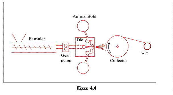 the extruder. Extruder throat should be cooled to assist feeding and prevent melting when the extruder is shutdown. The design of the extruder screw must be such that a deeper feed section should be used for better feeding and it should have ability to receive granule and pellets. A shallower metering section is required for higher shear and better pumping. The compression ratio must be greater than 3.5. The screws with chrome platting with normal flight tip hardening are preferable. In the transition/melting section, the barrier flight can improve melting rate and melt quality.
For melt filtration, a screen changer down stream of extruder is must. Fine mesh screen (325 mesh screen) is recommended to remove undispersed pigment, carbonized materials, etc. A metering pump is needed to maintain a constant output rate, otherwise the extruder may not be able to provide sufficient pressure due to low melt viscosity. The pump inlet pressure is lower than the typical fiber spinning/melt blown process. This is important for maintaining product quality. A static melt mixer may be used at the entrance to the die Maintain good melt temperature homogeneity.
The compressed air has been the major cost component of the process. The lower the process pressure requirement, the lower the energy cost. The requirement for air is typically 500-1500 m3/h/m die width. Air handling around the process area is very important. The handling of the make up air and the exhaust air are important.
The die system is known to be one of the important components of meltblown technology. There are generally two die systems used. The “exxon” die system was developed in early 60’s by Exxon Chemical Company. It was a coat hanger die feeding a single row of capillaries and one piece die tip construction. There were 25-35 capillaries per inch of die width. The advantage of this system is that higher quality web can be produced, but the disadvantage is that the output per unit die width may be limited. The “biax-fibrefilm” die system has multiple rows of spinning nozzles and concentric air holes. There are around 200 capillaries per inch of die width up to 12 rows of capillaries. The advantage of this system is that higher output per unit die width may be obtained (higher hole density), but the disadvantage is that it is more challenging to maintain uniformity at each hole (air and polymer flow rate and temperature) and it results in broader fiber size distribution.
The design of air plate is also important. The air gap and set-back are adjustable. Typical air gap is around 0.5-1.0 mm. A smaller air gap results in higher air velocity, but lower air volume. A larger air gap results in lower air velocity, but higher air volume. The en trapment of secondary air for cooling is also required. Typical set-back is around 0.8-1.2 mm
Ambient air is often used for cooling. Auxiliary cooling devices are also used. Water spray or cold air is used. In water spray, multiple nozzles create a fine water mist. This has been an excellent way of quenching fibers. It can be used to incorporate hydrophilic agent. Its position must be as close to die tip as practical. The water must be sprayed uniformly across the whole width. It is however difficult to keep all nozzles clean and functioning and used mostly in sorbent product where high output is a must. The cold air works in the same principle as that of water spray. It is however less effective as compared to water spray.
While forming webs, the fibers are distributed (spread) on a moving belt or rotating drum. The suction underneath the forming web removes drawing air and holds the fiber to the web. The distance to forming web (die to collector distance) affects the web properties. The belt collector provides good fiber support and retention as well as good web release. It should have minimum wire mark onto the web and proper air flow (maximum air flow with minimum openings). The most of the belts are constructed of 100% polyester strand materials. The drum collector is generally used in small lines, less critical applications. Its advantages are simpler, lower cost, easier to operate, less space requirement, etc. But, its disadvantages are lying in the difficulty to dissipate heat (metal screen).
Key process factors
The key process parameters in meltblown technology are polymer melt temperature, polymer throughput rate, process (primary) air temperature, process (primary) air flow rate, and die-to-collector distance. The aforesaid process variables play important roles in deciding the morphology and diameter of the fibers which are the building block of the meltblown nonwovens.
Melt temperature controls the melt viscosity of polymer at die. To increase melt temperature, increase the die temperature, the extruder barrel temperatures (last 2-3 zones) and all zones between die and extruder. Melt temperature decreases with increasing screw speed /output rate, this needs to compensate for lower melt temperature by using a higher barrel temperature at high screw speed/output rate. Higher melt temperature results into finer fiber, more tendency to produce “shots”, higher energy cost (heating and cooling), shorter die tip life (degradation of pigment, polymer, etc.) The PP with 1500 MFR has a very low melt viscosity (< 10 pa-sec at normal processing temperature). The viscosity stays fairly constant over a wide range of shear rate (close to Newtonian fluid)
The polymer throughput rate can be increased by increasing the screw speed. Typical throughput rate is 0.2-0.8 g/hole/min for most of the applications (e.g. battery separator, filtration media, etc.), but for some other applications (e.g., wipe, oil sorbent, etc.), it varies from 0.8 g/hole/min to 3 g/hole/min. The output rate affects fiber size, the higher is the output rate, the more is the size of the fibers. With higher output rate, it is more difficult to achieve good quality web.
The process air temperature offers limited range. It is typically kept to be the same or slightly higher than die temperature (depending on thermocouple location). The lower air temperature results in better fiber cooling, less shots, whereas higher air temperature results in finer fiber diameter and more energy cost.
Primary airflow affects fiber entanglement significantly. Increasing primary airflow rate reduces fiber entanglement, especially when DCD is shorter. Fine fiber bundles are affected more than coarse fiber bundles when the primary airflow is changed. The influence of primary airflow rate on fiber entanglement is reduced at larger airflow rates. Increasing primary airflow rate generally increased global orientation of fibers in the machine direction. Increasing primary airflow rate reduces pore cover in the webs substantially. This is thought to occur because the increased airflow decreases fiber entanglement and reduces fiber diameter.
The die to collector distance plays an important role on the quality of meltblown nonwoven. The higher distance results in higher fiber entangling, bulkier and softer web, better fiber cooling, less tendency to disturb fiber lay down, less web uniformity, and is used for heavy basis weight fabric (sorbent products, etc.). The lower distance results in less fiber entangling, more compact/stiffer web, balance of process air and suction capability, more uniformed web with better barrier properties, and is used for light basis weight fabric, especially light weight spunmelt composites.
Applications
Owing to the smaller fibres and larger surface area occupied by the fibres the meltblown nonwovens offer enhanced filtration efficiency, good barrier property, and good wicking property. They are finding applications in filtration, insulation, and liquid absorption.
Spunbond versus Meltblown
It is interesting to note the differences between the spunbond and meltblown technologies and products thereof. The meltblown technology requires polymers with considerably lower melt viscosity as compared to the spunbond technology. The initial investment for spunbond technology is three to four times higher than that for meltblown technology. The meltblown technology consumes more energy than the spunbond technology because of the usage of compressd hot air. The meltblown nonwoven is generally found to be costlier than the spubnnond nonwoven.
References
Many types of rayons, including viscose and cuprammonium rayon, are successfully processed into usable Spunbond nonwovens using wet spinning technology.
Source: http://www.nptel.ac.in/courses/116102014/Nonwovens_DDas_text%20content/Module_4.doc
Web site to visit: http://www.nptel.ac.in
Author of the text: indicated on the source document of the above text
If you are the author of the text above and you not agree to share your knowledge for teaching, research, scholarship (for fair use as indicated in the United States copyrigh low) please send us an e-mail and we will remove your text quickly. Fair use is a limitation and exception to the exclusive right granted by copyright law to the author of a creative work. In United States copyright law, fair use is a doctrine that permits limited use of copyrighted material without acquiring permission from the rights holders. Examples of fair use include commentary, search engines, criticism, news reporting, research, teaching, library archiving and scholarship. It provides for the legal, unlicensed citation or incorporation of copyrighted material in another author's work under a four-factor balancing test. (source: http://en.wikipedia.org/wiki/Fair_use)
The information of medicine and health contained in the site are of a general nature and purpose which is purely informative and for this reason may not replace in any case, the council of a doctor or a qualified entity legally to the profession.
The texts are the property of their respective authors and we thank them for giving us the opportunity to share for free to students, teachers and users of the Web their texts will used only for illustrative educational and scientific purposes only.
All the information in our site are given for nonprofit educational purposes