
Pressure measurement is important in many fluid mechanics related applications. From appropriate pressure measurements velocity, aerodynamic forces and moments can be determined. Pressure is measured by the force acting on unit area. Measuring devices usually indicate differential pressure i.e. in relation with atmospheric pressure. This is called gauge pressure. The measured pressure may be positive or negative with reference to the atmospheric pressure .A negative gauge pressure is referred to as vacuum.
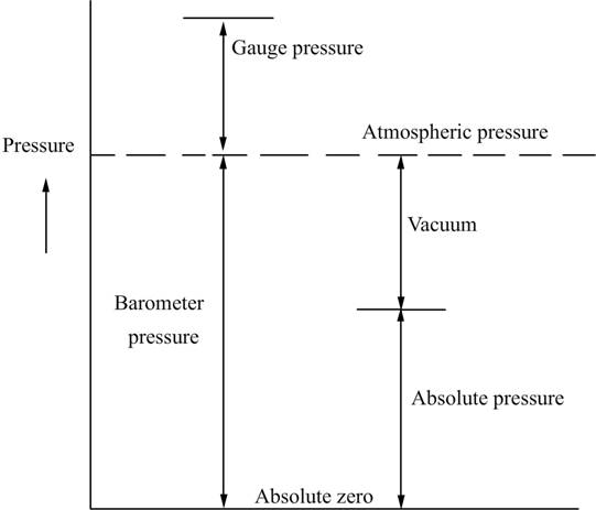
Fig.5.1 Explanation of the pressure terminology
5.1 Units of pressure
1Pascal(1N/m2) = 10dyne/cm2
1mmHg = 133.32pascals
= 13.595mm Water
Standard atmosphere = 1.013 * 105N/m2
1 millibar = 1000 dyn/cm2
1 micron = 10-6mHg
1 torr = 1 mmHg
= 1000micron
Absolute pressure
Absolute pressure is determined as algebraic sum of the readings of a barometer and of a manometer showing the gauge pressure. Manometers which measure absolute pressure are also available. They measure the pressure with reference to absolute zero pressure.
5.2 Pressure measuring devices
Main characteristics of manometers are pressure range, accuracy, sensitivity and speed of response. Pressure range of manometers varies from almost perfect vacuum to several hundreds of atmosphere. The conventional instruments used for pressure measurement are divided into the following groups.
5.2.1 Liquid column manometers
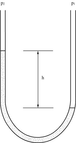
Fig. 5.2 Liquid column manometer
For amplifying the deflection in a liquid column manometer, liquids with lower density could be used or one of the limbs of the manometer may be inclined. Commonly used manometric liquids are mercury, water or alcohol. Some of the important and desirable properties of the manometric liquids are:
High thermal stability and low volatility are important for maintaining a constant. Specific gravity. High viscosity causes transmission lags .Thermal expansion causes changes in zero reading. While measuring low pressures, vapour pressure of the manometric fluid is an important consideration. Properties of some of the commonly used fluids are given in the Table 5.1.
Table 5.1 Typical properties of manometric fluids
Fluid |
Specific gravity |
B.P.( |
Surface Tension |
Viscosity |
Coeft.of Volumetric |
Methyl Alcohol |
0.792 |
64.7 |
22.6 |
0.59 |
|
Ethyl Alcohol |
0.789 |
78.4 |
22.0 |
1.9 |
110 |
Mercury |
13.55 |
356.59 |
465 |
1.55 |
18 |
Toluene |
0.866 |
110.8 |
28.4 |
|
|
CCl4 |
1.594 |
76.8 |
26.8 |
0.97 |
|
5.2.2 Inclined manometer
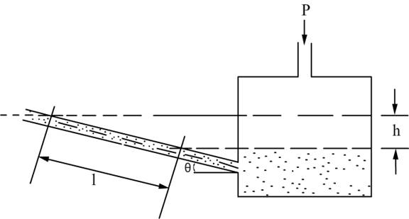
Fig. 5.3 Inclined manometer
The Figure 5.3 shows the amplification of the reading of applied pressure ‘h’ as
![]()
5.2.3 Mercury barometer
Barometer is the device used to measure the atmospheric pressure. Mercury barometer consists essentially of a glass tube sealed at one end and mounted vertically in a bowl or cistern of mercury so that the open end of the tube is submerged below the surface of mercury in the cistern. In the Fig.5.4 (i) the zero level of mercury in the cistern is shown under the influence of atmospheric pressure p1. When p2=p1 = atmospheric pressure, the zero level in the cistern can be marked. If the tube is open and if different pressures act in the cistern and in the tube, then there will be difference in the levels of mercury. If p1 is greater than p2 as shown in Fig.5.4 (ii), then mercury will be forced down in the cistern and corresponding rise will be there in the tube.
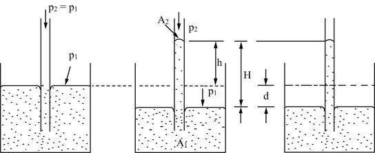
(i) (ii) (iii)
Fig. 5.4 Principle of mercury barometer
5.2.4 Micromanometer
For accurate measurement of extremely small pressure differences micromanometers are used .In the Figure 5.5 the instrument is initially adjusted such that p1 = p2 .
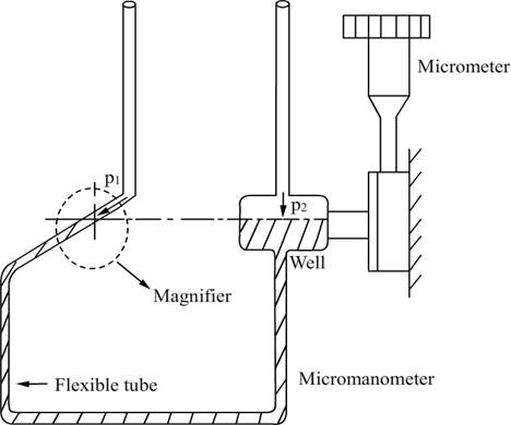
Fig. 5.5 Typical Micromanometer
The meniscus in the inclined tube is located at a reference level fixed by the hairline viewed through the magnifier. The reading of the micrometer is noted. Application of the unknown pressure difference causes the meniscus to move off the hairline but it can be restored to the initial position by raising or lowering the well (mercury sump) The difference in the initial and final micrometer readings gives the height of the mercury column and hence the pressure. Pressures as low as 0.025mm water column can be measured.
5.3 Mechanical manometers
Mechanical manometers provide faster response than liquid column manometers. In liquid column measurements, lag is due to the displacements of the liquid. In elastic sensing element type of manometers the time lag is due to the time required for equalisation of pressure to be measured with that in the sensing chamber. The deformation of elastic sensing elements is measured with the aid of kinematic, optical or electrical systems. There are three types of elastic sensing elements which are (i) Bourdon Tubes (ii) Diaphragms (flat or corrugated) (iii) Bellows
5.3.1 Bourdon tube
Bourdon tube is the oldest pressure sensing element .It is a length of metal tube of elliptical cross section and shaped into letter ‘C’.
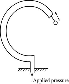
Fig.5.6 Bourdon tube pressure gauge
One end is left free and the other end is fixed and is open for the pressure source to be applied. A tube of elliptical cross section has a smaller volume than a circular one of the same length and perimeter. When connected to the pressure source it is made to accommodate more of the fluid. Resultant of all reactions will produce maximum displacement at the free end. Within close limits, the change in angle subtended at the centre by a tube is proportional to the change of internal pressure and within the limits of proportionality of the material; the displacement of the free end is proportional to the applied pressure.
The ratio between major and minor axes decides the sensitivity of the Bourdon tube. The larger is the higher is the sensitivity. Materials of the Bourdon tube is Phosphor bronze, Beryllium bronze or Beryllium Copper.
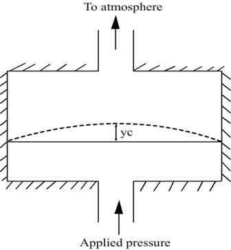
5.3.2 Elastic diaphragms
The pressure sensors making use of elastic diaphragms consist of a diaphragm fixed in a tubular member. The pressure to be measured is applied on one side. The mathematical relation between pressure and central deflection for a flat circular diaphragm is given by
 ……………………….. 5.5
To have a linear pressure deflection relation, the second and later terms should be small.
p = applied pressure
t = thickness
a = radius
yc = central deflection
E = Youngs modulus
![]() = Poisson’s ratio
= Poisson’s ratio ![]()
5.3.3 a) Corrugated diaphragms
Corrugated diaphragms permit considerably larger deflections than flat diaphragms. Their number and depth control the response and sensitivity. The greater the number and depth, the more linear is its deflection and greater is the sensitivity.
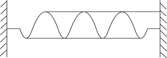
Fig. 5.8 Corrugated diaphragm
5.3.3 (b) Capsules, Bellows
For even larger deflections than the diaphragms corrugated diaphragms are made in to boxes or bellows. Bellows are most commonly used to measure small steady pressures.
5.4 Pressure Transducers
5.4.1 Diaphragm type pressure transducers
They convert the pressure to be measured into electrical signals. For example, pressure transducers whose operating principle is based on measuring changes in inductive, capacitive or ohmic resistances caused by the deformation of an elastic element.
Capacitance C = ![]() a/ d ………………….5.10
a/ d ………………….5.10
where ![]()
![]() absolute permittivity
absolute permittivity
![]()
a = area of plates
d = distance between the plates
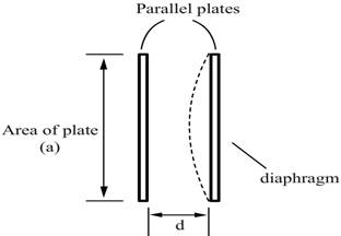
Fig.5.9 Elastic diaphragm used in a
parallel plate capacitor
With the application of pressure, the diaphragm deforms with the central deflection as shown. This changes the capacitance in an electrical circuit which can be calibrated against pressure to be measured.
5.4.2 Piezo-Electric pressure transducers
The word piezo-electric is derived from the Greek word “piezein” meaning squeeze or press. Certain materials possess the ability to generate electrical potential when subjected to mechanical strain. Conversely, they change dimensions when supplied with voltage. The potential developed by application of stress is not held under static conditions. Dynamic pressures in the range of frequencies from kHz to 100MHz can be measured using piezo-electric transducers. The use of piezo-electric effect is limited to dynamic measurements. Some materials exhibiting piezo electric properties are quartz, tourmaline, barium titanate, and Lead zirconate. Quartz is the preferred material, as it possesses good mechanical properties. Also, it is a good insulator least influenced by moisture.
5.4.3 Pressure Sensitive Paints (PSP)
They are composed of luminescent molecules dispersed in Oxygen permeable polymer binder.
When PSP is exposed to blue or an ultraviolet light the luminescent molecules are excited to a higher energy level.
From this excited state they can discharge in three ways:
Since the luminescent molecules react with Oxygen they collide and release light at the same time. The amount of light emitted is inversely proportional to the amount of Oxygen molecules on the surface.
5.5 Measurement of high pressures
5.5.1 Electrical resistance gauges – principle of operation
Bourdon Tube or strain gauge can be used for high pressures. Very high pressures (say above 1000bars) may be measured by means of electrical resistance gauges which are known as Bridgeman gauge. By way of principle of operation, they make use of resistance change brought about by direct application of pressure to the conductor itself. Referring to the Figure, the sensing element is the thin wire of Magnanin (84 Cu + 12 Mn + 4 Ni) or an alloy of Gold and Chromium (2.1%) which is loosely wound. When pressure is applied, bulk compression effects produce a change in resistance which may be calibrated against pressure. The general relation between electrical and mechanical may be derived as follows:
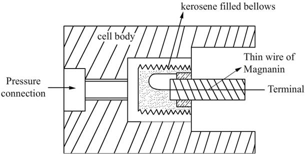
Fig.5.10 Sensor of a Bridgemans Gauge
![]() …………………………………………………………..(5.11)
…………………………………………………………..(5.11)
R = Resistance, ohms
L = Length of conductors
A = Area = CD2
where D is the diameter of the circular conductor and C a constant
![]() = Resistivity ohm cm
= Resistivity ohm cm
If the conductor is strained each of the quantities in the equation will change.
Differentiating

![]() ……………. 5.12
……………. 5.12
Dividing (5.12) by (5.11) gives
![]()
The wire will be subjected to biaxial stresses because the ends in providing electrical continuity will not be subjected to pressure.
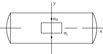
Fig.5.11 Bi-axial stresses on a small element
Let us consider a general element subjected to stresses which may be denoted as ![]() and
and ![]() .
.
Suppose ![]() and
and ![]() are applied one at a time. If
are applied one at a time. If ![]() is applied first, there will be strain in the
is applied first, there will be strain in the
x – direction = ![]()
Because of Poisson’s effect, the strain in y direction = ![]()
If ![]() is applied first
is applied first
Strain in y direction = ![]()
Strain in x direction = - ![]()
There will be a net strain of
![]()
![]()
Stresses are nothing but applied pressure
![]() assuming
assuming ![]()
Lateral Strain
![]()
![]()
Biaxial stress situation is assumed.
Longitudinal Strain
![]()
![]() (Substitute from above)
(Substitute from above)
= ![]()
![]()
If specific resistance ![]() does not depend on pressure
does not depend on pressure ![]() can be neglected.
can be neglected.
![]()
R = R0 (1 + bp) where, b = 2 / E.
![]() ………………………5.13
………………………5.13
where b is called pressure coefficient of resistance. Resistance varies linearly with pressure.
5.6 Ranges of different manometers
Liquid column manometers |
10 – 0.5 x 10⁶pascals |
Bourdon tubes |
Vacuum to a few thousand bars |
Diaphragms |
Vacuum to a few hundred bars |
Bellows |
Vacuum to a hundred bar |
5.7 Measurement of vacuum
Pressures below atmosphere is vacuum. Very low pressures may be defined as below 1mmHg. Ultra low pressures is less than a milli micron (<10-3micron )
Measurement of vacuum may be by two methods
Direct measurement
Resulting in a displacement caused by the action of force [Spiral Bourdon tubes, flat or corrugated diaphragm, capsules and various other manometers]
Indirect measurement or inferential methods
Pressure is determined through the measurement of certain pressure controlled properties such as volume, thermal conductivity etc.
5.7.1 Inferential methods
a) McLeod gauge
The working of McLeod Gauge is based on Boyles’ fundamental equation.
![]()
where p and V refer to pressure and volume respectively and subscripts 1 and 2 refer to initial and final conditions. Conventional McLeod gauge is made of glass. Refer to Fig. 5.12. It consists of the capillary ‘C’, bulb ‘B’ and the mercury sump which is connected to the lower end of the glass tube such that it can be moved up and down.
The pressure to be measured (the unknown pressure) is connected to the upper end of the glass part. When the mercury level in the gauge is below the cut off ‘F’, the unknown pressure fills the gauge including the bulb B and capillary C. When the mercury sump is moved up, the level in the gauge rises and when it reaches the cut off ‘F’ a known volume of gas at pressure to be measured is trapped in bulb B and capillary C.
Fig.5.12 Mc Leod gauge
Mercury is then forced up into the bulb and capillary. Assume the sump is raised to such a level that the gas at the pressure to be measured which filled the volume above the cut off is now compressed to the volume represented by the column h.
Suppose the original volume after then mercury reaches F is![]() . This is at a pressure being measured p1
. This is at a pressure being measured p1
As ‘ah’ is <<< V0 it is neglected.

Applications of McLeod gauge
McLeod gauge is used mainly for calibrating other inferential type of gauges. The shortcomings of the McLeod gauge are its fragility and the inability to measure continuously. The vapor pressure of Mercury sets the lower limit of measurement range of the gauge.
b) Thermal conductivity gauges
The working principle of thermal conductivity gauges is that at low pressures heat lost by a heated object by conduction through molecules will depend on pressure. This is valid only for certain pressure range.
When the mean free path is comparable with the dimensions of the gauge head the heat loss from a heated wire in the gauge head will be by (i) conduction through leads (ii) radiation to surroundings (iii) conduction through molecules.
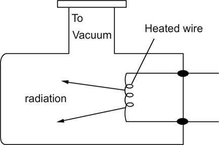
Fig.5.13 Gauge head of the thermal conductivity gauge
The range of thermal conductivity gauges is from mm of Hg to 10-3mmHg. At higher pressures, heat loss from the heated wire is insensitive to the pressure change. At lower pressure heat loss by (i) and (ii) become more significant. There are two kinds of the thermocouple gauges.
c) Pirani gauge
Measures change in resistance of the heated wire when it looses heat to the gas molecules in the gauge head. In this case the gauge is called pirani gauge.
d) Thermocouple gauge
Instead of measuring electrical resistance, a thermocouple is kept in contact with the heated wire and the temperature of the wire is directly measured as a measure of pressure.
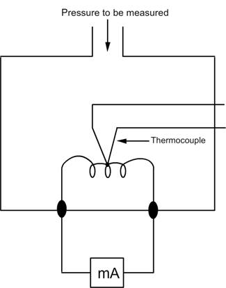
Fig.5.14 Thermocouple gauge head
e) Hot cathode ionisation gauges
At higher levels of vacuum, the measurement of pressure is by using Ionisation gauges. They operate on the principle of ionising the gas by means of electrons emitted by a heated filament. The kinetic energy acquired by an electron in passing through a potential difference of V volts corresponds to a value equal to V*e where e is the charge of the electron. When this energy exceeds a certain critical value corresponding to the ionization potential Vi, there is a possibility that collisions between molecules and electrons will result in the formation of +ve ions. The relatively high velocity electrons on hitting a gas molecule drives an electron out of it leaving it positively charged. For gases such as N2, O2 etc, Vi is ~ 15volts. The measurement of the ions produced is a measure of the pressure. The electrons are speeded up by an electric field and +ve ions produced are collected. The number of +ve ions formed will depend on the number of molecules and therefore on the pressure.
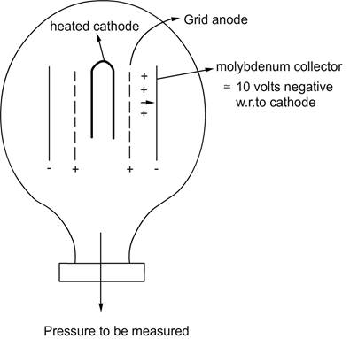
Fig.5.15 Ionisation gauge
The gauge consists of a cathode, grid anode and a negative plate. The negative plate is at ~10V negative with respect to the cathode. The electrons emitted by the hot cathode (filament) are speeded up by the electric field and the positive ions produced are collected by the negative plate.
g) Cold cathode ionisation gauge (Penning gauge)
This gauge also works on the ionization principle. Positive ions are produced by the electrons and current due to these ions gives a measure of the pressure. Electrons are ejected from a cold cathode of Zirconium, Thorium by electric discharge. The gauge consists of two plate cathodes and a ring anode . A potential difference of ~2KV is applied across the electrodes.
The travel of electrons is made over a much longer distance. The secondary electrons are made to travel in helical paths before reaching the anode. This is accomplished by a magnetic field.
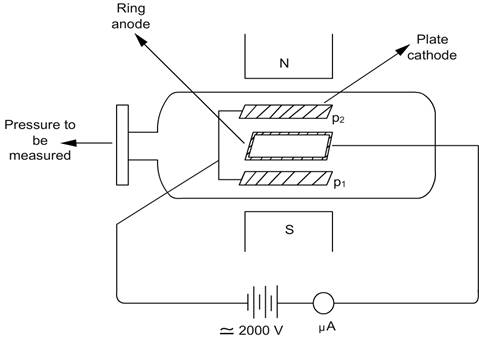
Fig.5.16 Cold cathode ionization gauge
Magnetic poles are kept such that the flux with lines of force is applied perpendicular to the two cathodes.
5.8 Measurement of pressure in flows
In flows, distinction has to be made between static and stagnation pressures.
Static pressure
Pressure acting on the surface of a body imagined to be moving with the fluid with the same velocity as the medium is the static pressure.
Stagnation pressure
It is the pressure of a fluid imagined to be brought to rest isentropically.
5.8.1 Measurement of static pressure
Common technique is to connect a probe to an orifice drilled perpendicular to the wall of the model where the streamlines are undistorted and parallel.
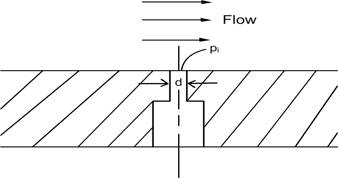
Fig.5.17 Static pressure orifice (tap) on a flat wall
Static hole diameter is about 1/5 of the boundary layer thickness. Practically the diameter is about 0.25mm on small models and 2.5mm on larger installations. The correctness of the static pressure measured is dependent on‘d’ the orifice diameter [Fig.5.17]. The influence of the orifice diameter on the error in static pressure measurements is given graphically in Fig.5.18.
Fig.5.18 Influence of error on orifice diameter
The static pressure orifices (taps) on the walls of the flow channel provide the wall static pressure. The wall static pressure can not be assumed to prevail inside the flow. In order to get the pressure inside the flow, probes of suitable design have to be made use of.
5.8.2 Static pressure probes for subsonic flow
The commonly used static pressure probe in subsonic flows is the Prandtl probe. The Prandtl probe is an intrusive device. The pressure sensing orifices on the periphery of the probe are carefully located such that the influence of the nose and stem of the probe nullify each other.
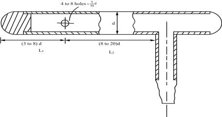
Fig.5.19 The Prandtl probe
Fig.5.20 The nose and stem effects in a Prandtl tube
Because of the intrusive nature of the probe, the flow will be accelerated by the nose. The effect will be to reduce the static pressure which is called the nose effect. In contrast, the effect of stem will be to locally stagnate the flow and thereby to increase the static pressure. This
effect is the stem effect. As shown in the Fig.5.20, the position of the orifices are so chosen that the two effects neutralize each other. Additionally the probe must be slender (say ~ 1.0 to 1.5mm dia) and kept parallel to the flow.
5.8.3 Static pressure probes for supersonic flow
When Mach number is more than 1.0, shock appears. When the cone angle of the probe is less than the shock detachment angle for the given Mach number [shown in Fig.5.23] and if the orifices are located well downstream of the shock wave, the measured static pressure will tend towards the value for the undisturbed flow. Conical or ogival shaped tubes are used.
Probes are made small and with static taps on the cone surface. The effect of yaw is reduced by arranging several orifices so that the pressure inside the tube is an average value. Usually the tube has 4 to 8 orifices whose diameter is about 1/10 th of the outside diameter of the tube.
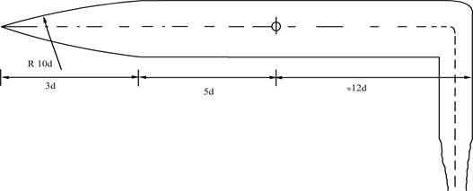
Fig.5.21 Ogival shaped static pressure probe for supersonic flow
Good results are obtained with ogival tubes. The tube shown in Fig.5.21 has a systematic error within 1%. Angle of the cone should be less than the angle at which the shock wave becomes detached from the cone. The error in the measurement of static pressure decreases as the distance of the orifice from the tip of the probe increases.
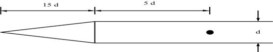
Fig.5.22 Conical static pressure probe for supersonic flow
Fig.5.23 Maximum deflection angle for different
Mach numbers
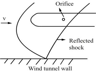
Fig.5.24 Reflection of the shock from the wall
It is important to have long pointed tubes. Otherwise there is the possibility that the reflected shock may affect the static pressure readings. Roughness at the edges of the orifices too may cause large errors in measurement.
5.9.1 Insubsonic flows
The gas particles come to rest so quickly at the stagnation point of a body, that heat transfer and friction losses are negligible. Therefore, in subsonic flows only isentropic changes occur. Hence the stagnation pressure measured in a subsonic flow is not significantly different from that in the settling chamber. Total pressure is measured with a Pitot tube which a cylindrical tube is having an orifice pointing towards the flow. Axis of tube must coincide with the flow direction. It is a practice to use tubes which generally have blunt ends.
Such tubes are insensitive to yaw upto ![]() to 120
to 120
The relation between the stagnation pressure measured and the static pressure may be expressed as follows:

where p0 is the total pressure and p the static pressure.
5.9.2 Insupersonic velocities
Shockwave appears upstream of the tube nose. Therefore tube measures only pressure behind the shock wave. Normal shock equations give the relation between the total pressures upstream and downstream of the shock. As the bow shock formed in front of the Pitot tube has the normal part only in the central region, the tube diameter for measurements in supersonic flow is usually kept very small.
5.10 Lag in manometric systems
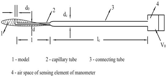
Fig.5.25 Wind tunnel model with the manometric system
When the pressure changes near the orifice which is connected to a manometer, equilibrium in the manometer is established not immediately but after a certain time. If the pressure is read of earlier there will be gross errors.
Fig.5.26 Transmission lag as a function of capillary diameter
Fig.5.cTransmission lag as a function of orifice diameter
Smaller transmission lags are necessary not only for high reliability but also for reducing the duration of experiments. Equilibrium will be established in the manometric system later after the pressure on the model is stabilized. The run times should be longer than the transmission lag.
Transmission lag is caused by:
The main factors influencing the transmission lag are the orifice diameter do, the diameter d of the capillary and dc of the connecting tube and their respective lengths l and lc .
The orifice diameter is of small influence when d/do < 2.5. When d/do > 2.5 the transmission lag increases sharply. The orifice diameter should not be less than half the diameter of the capillary tube. The influence of the diameter of the capillary tube is very strong. A reduction of this diameter has its main effect an increase in the resistance to the flow of gas. An increase in the length of the capillary tube has a significant effect on the lag. Capillary tubes should have larger diameter and shorter length.
Exercises
Answer the following
Work out the following numerical problems
Source: http://www.nptel.ac.in/courses/101106040/chapter%205.doc
Web site to visit: http://www.nptel.ac.in
Author of the text: indicated on the source document of the above text
If you are the author of the text above and you not agree to share your knowledge for teaching, research, scholarship (for fair use as indicated in the United States copyrigh low) please send us an e-mail and we will remove your text quickly. Fair use is a limitation and exception to the exclusive right granted by copyright law to the author of a creative work. In United States copyright law, fair use is a doctrine that permits limited use of copyrighted material without acquiring permission from the rights holders. Examples of fair use include commentary, search engines, criticism, news reporting, research, teaching, library archiving and scholarship. It provides for the legal, unlicensed citation or incorporation of copyrighted material in another author's work under a four-factor balancing test. (source: http://en.wikipedia.org/wiki/Fair_use)
The information of medicine and health contained in the site are of a general nature and purpose which is purely informative and for this reason may not replace in any case, the council of a doctor or a qualified entity legally to the profession.
The texts are the property of their respective authors and we thank them for giving us the opportunity to share for free to students, teachers and users of the Web their texts will used only for illustrative educational and scientific purposes only.
All the information in our site are given for nonprofit educational purposes