
A process flow diagram (PFD) is a diagram commonly used in chemical and process engineering to indicate the general flow of plant processes and equipment. The PFD displays the relationship between major equipment of a plant facility and does not show minor details such as piping details and designations. Typically, process flow diagrams of a single unit process will include the following:
Process flow diagrams generally do not include:
Process flow diagrams are high levels drawings usually of multiple process systems within a large industrial plant and may be called block flow diagrams or schematic flow diagrams. Figure 1 illustrates a typical PFD for an evaporator 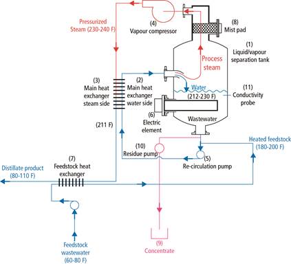
system.
Figure 1 – PFD of Typical Evaporator system
The P&ID shows the interconnection of process equipment and the instrumentation used to control the process. In the process industry, a standard set of symbols is used to prepare P&ID drawings of processes as can be seen in Figure 2 below. For processing facilities, a P&ID is a pictorial representation of the following:
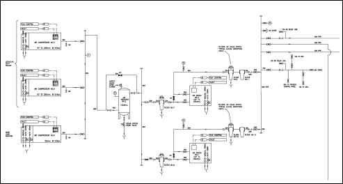
Figure 2 – P&ID of Typical compressed air system
As a rule P&IDs do not have a drawing scale and present only the relationship or sequence between components. Just because two pieces of equipment are drawn next to each other does not indicate that in the plant the equipment is even in the same building; it is just the next part or piece of the system. These drawings only present information on how a system functions, not the actual physical relationships. Because P&IDs provide the most concise format for how a system should function, they are used extensively in the operation, repair, and modification of the plant.
Figure 3 – Common Isometric Pipe symbols
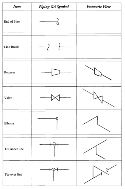
Figure 4- Common GA Pipe symbols
Title |
Author |
Ref. Code |
The Induction Book, “Code of Behaviour & Health & Safety Guidelines” |
SOLAS |
|
Basic Welding and Fabrication |
W Kenyon |
ISBN 0-582-00536-L |
Fundamentals of Fabrication and Welding Engineering |
FJM Smith |
ISBN 0-582-09799-1 |
Workshop processes, practices and materials, 3rd edition, Elsevier Science & Technology |
Black, Bruce J 2004 |
ISBN-13: 9780750660730 |
New Engineering Technology |
Lawrence Smyth & Liam Hennessy |
ISBN 086 1674480 |
Source: http://local.ecollege.ie/Content/APPRENTICE/liu/pipefitting/word/M5_U4_Drawings%20For%20Pipe%20Installation.doc
Web site to visit: http://local.ecollege.ie
Author of the text: indicated on the source document of the above text
If you are the author of the text above and you not agree to share your knowledge for teaching, research, scholarship (for fair use as indicated in the United States copyrigh low) please send us an e-mail and we will remove your text quickly. Fair use is a limitation and exception to the exclusive right granted by copyright law to the author of a creative work. In United States copyright law, fair use is a doctrine that permits limited use of copyrighted material without acquiring permission from the rights holders. Examples of fair use include commentary, search engines, criticism, news reporting, research, teaching, library archiving and scholarship. It provides for the legal, unlicensed citation or incorporation of copyrighted material in another author's work under a four-factor balancing test. (source: http://en.wikipedia.org/wiki/Fair_use)
The information of medicine and health contained in the site are of a general nature and purpose which is purely informative and for this reason may not replace in any case, the council of a doctor or a qualified entity legally to the profession.
The texts are the property of their respective authors and we thank them for giving us the opportunity to share for free to students, teachers and users of the Web their texts will used only for illustrative educational and scientific purposes only.
All the information in our site are given for nonprofit educational purposes