
First Order Circuits: RC and RL Circuits
Circuits that contain energy storage elements are solved using differential equations.
The “order” of the circuit is specified by the order of the differential equation that solves it.
Let’s consider a circuit with just one capacitor or one inductor, i.e. a first order circuit.
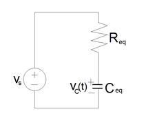
If you considering viewing the circuit from the perspective of the energy storagy element,
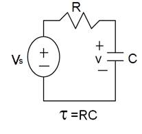
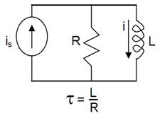
then by Thevenin’s and Norton’s Theorems we can always reduce a first order circuit to one of these:
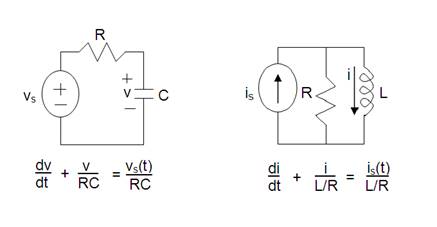
To solve for the capacitor voltage or the inductor current we need to find solve the equation shown below each of these circuits. These equations merely came from applying KVL (to the circuit with the capacitor) and KCL (to the circuit with the inductor).
How do we solve these equations?
Note that they all have the same mathematical form!
The form is a homogeneous, (i.e. one variable), linear, (i.e. first order), differential equation.
The solution to these differential equations are functions of time: v(t) or i(t)
We can re-write both equations above in a general way as follows:
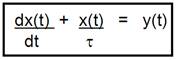
where
So to solve a first order circuit (i.e. solve for v(t) or i(t) ), we need to solve this differential equation.
After some work (and taking a class in differential equations) we get the solution:
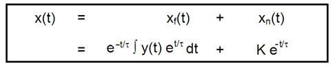
The solution to a differential equation always has two parts:
A forced response, xf(t), and a natural response, xn(t). (They have other names too.)
Together they form the complete response, x(t).
K is an arbitrary constant of integration that shows up in the natural response and is determined from the initial conditions. (There will be the same number of arbitrary constants as the order of the equation. In this case there is only one because it is a first order differential equation.)
We can see from this that the solution to a first order circuit will depend on the type of forcing function, y(t), in the circuit.
Consider the solutions for 4 different forcing functions:
A Source Free Circuit
The case of y(t) = 0
The solution is:
![]()
A DC Circuit
The case of y(t) = constant, M
The solution is:
![]()
alternatively :
![]()
An exponential circuit
The case of y(t) = Aebt
The solution is:
![]()
An ac circuit
The case of y(t) = A sin(wt + q)
The solution is:
![]()
Notes about the natural response, xn(t):
Notes about the forced response, xf(t):
Notes about t:
Response of a first order circuit with a constant source
Here is the plot of the solution of an RL or an RC circuit with a constant source
where the final value of current or voltage is less than the original value.
x = xinfinity + [x0 - xinfinity] e– t/t
where xinfinity < x0
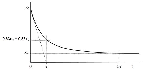
Note: A larger value of t means a longer time to reach its final value, i.e. a slower decay.
Here is the plot of the solution of an RL or an RC circuit with a constant source
where the final value of current or voltage is greater than the original value.
x = x¥ + [x0 - x¥] e– t/t
where x¥ > x0
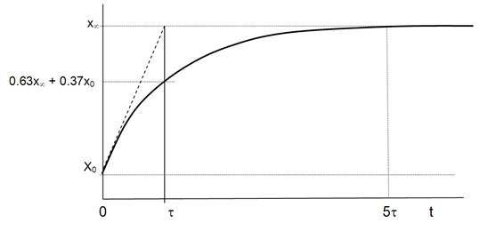
Note: A larger value of t means a longer time to reach its final value.
How do the values of R and C affect the time constant in an RC circuit?
Question:
For an RC circuit, large values of C or large values of R will cause a larger t.
Consider disconnecting the voltage source. Why would a large C or R cause the circuit to take a long time to discharge? (i.e. reach the final value of zero voltage across the capacitor.)
Answer:
A large value of C allows greater energy to be stored in the capacitor.
A large amount of energy will require a longer time to be dissipated in the resistor.
A large value of R means that power dissapated in it (p = v2/R) will be less for the same initial energy stored in the capacitor (i.e. the initial voltage, vo = vs).
Hence it will take a longer time to dissipate the stored energy.
How do the values of R and L affect the time constant in an RL circuit?
Question:
For an RL circuit, large values of L or small values of R will cause a larger t.
Consider disconnecting the current source. Why would a large L or a small R cause the circuit to take a long time to reach the final value of zero current through the inductor?
Answer:
A large value of L allows greater energy to be stored in the inductor.
A large amount of energy will require a longer time to be dissipated in the resistor.
A small value of R means that power dissapated in it (p = i2R) will be less for the same initial energy stored in the inductor (i.e. the initial current, io= is).
Hence it will take a longer time to dissipate the stored energy.
The procedure to find the response of ANY first order dc circuit
For a first order circuit with an inductor (RL circuit) and a constant source:
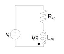
It will ALWAYS have this form:
iL(t) = if(t) + in(t)
where
if = iinfinity
in = [i0 – iinfinity] e-t/t
So you just need to find 3 things:
For a first order circuit with a capacitor (RC circuit) and a constant source:
It will ALWAYS have this form:
vC(t) = vf(t) + vn(t)
where
vf = vinfinity
vn = [v0 – vinfinity] e-t/t
So you just need to find 3 things:
The Unit-Step Forcing Function
Singularity functions are discontinuous functions or have discontinuous derivatives.
One example is the unit-step forcing function or the unit-impulse function.
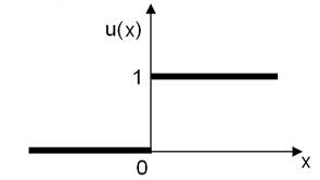
This is the definition of the unit-step forcing function:
u(x) = 0 for all x < 0
u(x) = 1 for all x > 0
note: this is not defined for x=0
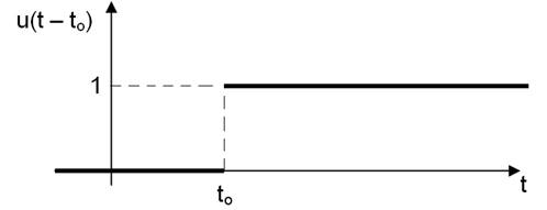
Consider x = ( t – to)
u ( t – to) = 0 for all t < to
u ( t – to) = 1 for all t > to
note: this is not defined for t = to
The unit step forcing function is zero when the argument is less than zero and 1 when the argument is greater than zero.
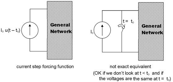
We can model switches with this unit step forcing function.
Consider a voltage source being switched into a general network:
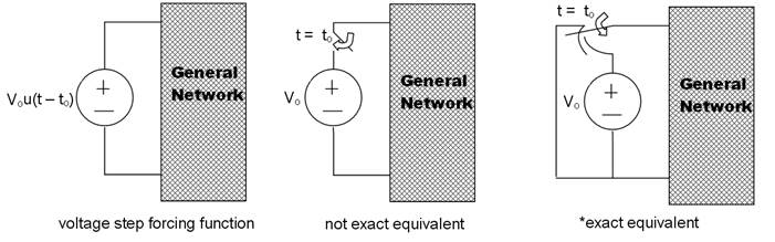
*equivalent means the voltage current characteristic of the two networks are identical.
This is not the exact equivalent because the voltage across the switch and battery is completely unspecified. This will be equivalent if we don’t care about t < to and if currents which flow from the two networks are identical at t = to.
Consider a current source beingswitched into a general network:
The rectangular voltage pulse:
v(t) = 0 for all t < to
v(t) = Vo for all to < t < t1
v(t) = 0 for all t1 < t
note: this is not defined for t = to or for t = t1
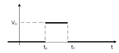
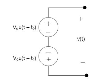
We can model this pulse with unit step forcing functions:
v(t) = Vou(t - to) – Vou(t - t1)
A note about stability:
f(t) = ff (t) + fn(t)
fn(t) = Ae-t/t
If t > 0 then lim fn(t) as t approaches infinity = 0
i.e. the transient response dies out.
This is stable.
The forced response depends on the input to the circuit.
However, if t < 0 then lim fn(t) as t approaches infility is infinity!
i.e. the transient response does not die out! It increases exponentially!
This is unstable.
The forced response is negligible.
For the case of instability, it looks as if the natural response will grow without bound. This looks scary! But don’t worry. This is not the case. It will grow until something happens such as the saturation of an op-amp, or a dependant source, or the destruction of a circuit element.
None of these things are desirable and so it is usually not desirably to have an unstable circuit.
Differential Operators
An operator is a symbol that represents a mathematical operation.
We define the differential operator, s, such that:
so = 1
s1x = dx/dt
s2x = d2x /dt2
snx = dnx /dtn
1/s = ![]()
The advantage is that s can be treated algebraically.
So differential equations can be transformed into algebraic ones, solved and then transformed back into the differential equations.
The operator 1/s satisfies the usual rules of algebraic manipulations including commutative:
s x 1/s = 1/s x s = 1
This is actually only true when x(-infinity) = 0
This doesn’t bother us because we require all capacitor voltages and inductor currents to be 0 at t = -infinity
Source: https://fog.ccsf.edu/~wkaufmyn/ENGN20/Course%20Handouts/Chap%208%20First_Order_Circuits.doc
Web site to visit: https://fog.ccsf.edu
Author of the text: indicated on the source document of the above text
If you are the author of the text above and you not agree to share your knowledge for teaching, research, scholarship (for fair use as indicated in the United States copyrigh low) please send us an e-mail and we will remove your text quickly. Fair use is a limitation and exception to the exclusive right granted by copyright law to the author of a creative work. In United States copyright law, fair use is a doctrine that permits limited use of copyrighted material without acquiring permission from the rights holders. Examples of fair use include commentary, search engines, criticism, news reporting, research, teaching, library archiving and scholarship. It provides for the legal, unlicensed citation or incorporation of copyrighted material in another author's work under a four-factor balancing test. (source: http://en.wikipedia.org/wiki/Fair_use)
The information of medicine and health contained in the site are of a general nature and purpose which is purely informative and for this reason may not replace in any case, the council of a doctor or a qualified entity legally to the profession.
The texts are the property of their respective authors and we thank them for giving us the opportunity to share for free to students, teachers and users of the Web their texts will used only for illustrative educational and scientific purposes only.
All the information in our site are given for nonprofit educational purposes