
Commonly used as an alternative to riveting for jointing thin plate and light gauge metal. The spot welder has control over the three adjustments, current flow, timing of weld and pressure applied. Adjustment can also be made to arms of electrode holders, to accommodate various shapes of work. Electrodes can be obtained in vertical and offset form.
Electrodes are generally made of copper, for certain classes of work they may be tipped with harder material i.e. tungsten or copper alloy. Electrodes are generally water cooled, with the water supplied through the hollow electrodes. Care should be taken when changing electrodes not to damage the tapered seating.
The basic principle of spot welding is two pieces of metal to be joined are clamped between two copper electrodes, which are connected to a power source. As electricity is passed from one electrode to the other and metal clamped between them acts as a resistor. This causes a build –up of heat and melts the metal thus welding them together. Tips should be filed regularly and the cooling system used.
Principles of Resistance Spot Welding
3.1 Application of Resistance Spot to Vehicle Body
Resistance welding is a joining process belonging to the pressure welding sector. With it’s locally applied heat and pressure. It has an obvious relationship with the forge welding technique practiced by blacksmiths when joining metal. The resistance welding process was invented in 1877 by Professor E. Thomson of Philadelphia, USA, when an accidental short circuit gave him the idea for what was originally termed short circuit welding. From the beginning of the Twentieth Century it was used on a small scale in industry, but it was only after the Second World War that resistance spot welding had its real beginning in the automotive industry. It has since grown to be the most important method of welding used in the construction and mass-production of vehicle bodies.
Resistance welding is extensively used for the mass production assembly of the all-steel body and its components sheet metal parts. Its width adoption has been brought about by its technical advantages and the reduction in cost. Most mass produced car bodies are assembled entirely by welding steel pressings together to produce an integral rigid chassis and body structure. Low-carbon steel thickness used in this unitary construction range from 0.8 – 1mm, for skin or floor panels to 3mm for major structural pressings such as suspension brackets. Intermediate gauges such as1.2mm are used for hinge reinforcements, 1.6mm for chassis structural members and 1.8mm - 2.5mm for suspension and steering members. With the introduction of high strength steels (HSLA steels), car manufacturers are producing body panels as thin as 0.55mm, and structural members with gauges of between 1.2mm and 2mm. This reduction in thickness can be made without loss of strength.
There are a number of resistance welding processes. Resistance spot welding is the most widely used welding process in car body construction; there are approximately 4500 to 6000 spot welds per body which accounts for 80 per cent of the welding used. A further 10 per cent is composed of other resistance welding processes; seam, projection, flash and butt welding. The remaining 10 per cent is divided between MIG/MAG welding techniques used in the mass production of car bodies, resistance welding dominates the field.
The fundamental principle is upon which all resistance welding is based lies in the fact that the weld is produced by the heat obtained from resistance to flow of an electric current through two or more pieces of metal held together under pressure by electrodes which are made from copper or copper alloys. The engineering definition of heat (heat being the essence of all welding) is (energy) X time. This indicates a balance between energy² input and weld time; therefore the faster the welding; the greater the clamping force. However, the engineering definition of resistance is such that the higher the clamping force, the greater the current needed to produce a constant heat. Heat is generated by the resistance of the parts to be joined to the passage of a heavy electric current. This heat at the junction of the two parts changes the metal to a plastic state. When the correct amount of pressure is then applied fusion takes place. There is a close similarity in the construction of all resistance welding machines, irrespective of design and cost. The main difference is in the type of jaws or electrodes which hold the object to be welded. A standard resistance has four principle elements;
Frame: The main body of the machine, which differs in size and shape for robot, stationery and portable types.
Electrical circuit: Consists of a step-down trans-former, which reduces the voltage and portionally increases the amperages to provide the necessary heat at the point of the weld.
Electrodes: Include the mechanism for making and holding contact at the weld area.
Timing Control: Represents the switches which regulate the volume of current, length of current time and contact period. Many now include adaptive in-process control units (pulsing weld timer).
The principal forms of resistance spot welding are classified as: resistance spot welding; resistance projection welding; resistance seam welding; resistance flash welding and resistance butt welding.
3.2 Resistance Spot Welding
Resistance spot welding is basically confined to making welds approximately 6mm diameter between two or more overlapping sheet metal panels. This type of welding is probably the most commonly used type of resistance welding. The art of production planning for spot welding is to simplify the presentation of panels in the region of mutual panel overlap. The limitation of spot welding is that the electrode assemblies have to withstand applied
forces ranging from 2200N to 4500N for the range of sheet steel thickness used in vehicle construction and repair. Product design of planning must account, therefore, for the requirement that the electrodes, which are constructed from relatively weak copper alloys, need normal access to both sides of the overlapping panels to withstand such electrode forces. The material to be joined is placed between two electrodes, pressure is applied, and the electric current passes from one electrode through the material to the other electrode. There are three stages in producing a spot weld. First, the electrodes are brought against the metal and pressure is applied before the current is turned on. Next the current is on momentarily. This is followed by the third hold time, in which the current is turned off but the pressure continued. The hold time forges the metal while it is cooling.
Regular spot welding usually leaves slight depressions on the metal that is often undesirable on the show side of the finished product. These depressions are minimised by the use of larger-sized electrode tips on the show side. Resistance spot welding can weld dissimilar metal thickness combinations by using a larger electrode contact tip area against the thicker sheet. This can be done for mild steel having a dissimilar thickness ratio 3:1.
There are three kinds of distortion caused by resistance spot welding which are relevant to car body manufacture and repair. The first is the local electrode indention due to the electrode sinking into the steel surface. This is a mechanical distortion – a by product of
the spot welding process. Second, there is a small amount of thermal distortion which is trouble-some when attempting to make spot welds on show surfaces such as skin panels without any discernable metal distortion. Last, there is the gross, distortion caused when badly fitting panels are forced together at local spots. This a mechanical distortion totally connected with the spot welding process. Second, there is small amount of thermal distortion which is troublesome when attempting to make spot welds on show surfaces such as skin panels without any discernible metal distortion. Last, there is the gross, distortion caused when badly fitting panels are forced together at local spots. This is a mechanical distortion totally unconnected with the spot welding process; the same type of distortion with rivets or with any similar localised joining method. A combination of all these distortions contributes to the general spot weld appearance, which is virtually unacceptable on a consumer product. The technique on car bodies is to arrange for spot welded flanges to be either covered with trims (door apertures), or with a sealing weather strip (window and screen surrounds). The coach joint is one of the features that distinguish a cheap, mass produced body from an expensive hand built one. Spot welders are made for both DC and AC.
Typical resistance spot-welding rates are 100 spots per minute. To dissipate the heat at the weld as quickly as possible, the electrode the electrodes which conductors are sometimes water cooled. Although many spot welders are of the stationery design, there is an increased demand for the more manoeuvrable portable type. The electrodes which conduct the current and apply the pressure are made of low-resistance copper alloy and are usually hollow to facilitate water cooling. These electrodes must be kept clean and correctly to produce good results. Spot welders are used extensively for welding steel, and when equipped with an electronic timer they can be used for metal such as aluminium, copper, stainless and galvanised.
Today’s chassis-less bodies hold engine, suspension and steering in the right places and are designed to absorb the impact of crashes by crumpling, thus shielding the passenger compartment (and its passengers) from shock and deformation. From the viewpoint of safety as well as mechanical efficiency, proper welding is vital in this kind of repair.
Car body design demands careful choice of the sheet metal, which was, until recent years, all mild steel. Tensile strength and ductility, which are good in mild steel, are vital to ‘crumplability’ ( the ability to absorb the impact energy), and this is why resistance spot welds are used. The average body shell is joined together by approximately 4500-6000 such spot welds. These remain ductile because the welding process does not alter the original specifications of the steel. Lighter body weight reduces the load on the car engine and therefore has a direct influence on petrol consumption.
For weight and fuel saving reasons, high strength steels have been introduced for some panel assemblies on body shells. As these steels have different characters from low-carbon steel (mild steel), which still accounts for 60 per cent of the body shell, they cause repair welding problems. Higher-strength steels have been made specifically for motor car manufacturers to produce body shells from thinner but stronger steel sheet. These steels are less ductile and are harder. Above all, they do not tolerate excess heat from bad welding, which makes them brittle or soft or can cause panel distortion. Low carbon steel tolerates excess heat well. While older all-mild steel bodies essentially needed only to have the welding machine set for the metal thickness, current new bodies can contain steel of up to four different strengths, hardnesses and ductilities, some coated on one side, some coated on both sides and some uncoated. Zinc coated sheet materials require the use of heavier welding equipment capable of producing a higher current to penertrate the zinc coating , and the electrodes must be constantly maintained by cleaning to avoid zinc pick-up when welding.
The repair of bodies incorporating lo-carbon steels and HSLA steels therefore demands very different welding routines from those for low-carbon steel alone. Low-carbon steel bodies can be resistance spot welded or gas (TIG) welded or arc (MIG) welded; but higher-strength steels should not undergo the last two processes, because they involve nearly three times the heat of resistance spot welding. The temperatures generated are over 1350ºC for resistance spot welds, for joints of similar strength. Higher-strength steels, however, with their higher tensile strength, limited ductility and greater hardness, are particularly vulnerable to heat and are apt to lose strength and change ductility when overheated.
Developments in welding equipment combined with the use of electronic controls have opened the way to new body repair welding techniques that help to simplify the practical problems posed by bodies made from a mixture of low-carbon and high-strength low-alloy steels. The traditional resistance welding method has had to be
improved to join higher-strength steels. Because the weld current flow is hindered by the steel’s coating, these may require higher temperatures to break them down before a weld can be formed. For producing consistently good welds it is necessary to use two or three stages for welding, the duration of each stage being adapted to the nature of the steel and its coating.
3.3 Resistance Spot Welding of High-Strength Steels
The rigidity of the body and its ability to withstand high torsional and other stresses depend on the assembly method used to bring the various body panels together. Spot welding is used throughout the industry for two reasons: first, because it is the strongest and most reliable method of joining two pieces of metal: and second, because of the total absence of panel distortion through the welding. In order to effect a satisfactory repair, vehicles welds having the same characteristics as the original are essential.
A comparison between an electrical spot weld and a forged weld shows that in both these processes a union is formed by an amalgamation of the metal molecules. These have been consolidated in each of the two pieces, despite the difference in the two processes employed. In the case of forge welding the pieces are heated in the forge furnace and then hammered until a homogeneous material results. In the case of the spot-welding process the gun must have a pressure device which can be operated by the user and transmits the pressure to the electrodes and a transformer to enable current at high intensity to be fed to the electrodes. Spot welding is the primary body production welding method. Most production welding is carried out on metal gauges of less than 2.5mm, although greater thicknesses can be spot welded. With the introduction of high-strength steels, car manufactures are producing body panels as thin as 0.55mm and using gauges of between 1.2 and 1.5mm for structural members. By using the correct equipment, two-sided spot welding can be successfully accomplished on these steels.
3.4 Weld Quality
Careful control of three factors is necessary to make a good-quality spot weld:
The main disadvantage associated with welding in general is that any visual inspection of the weld gives no indication of the weld quality. It is therefore essential, that spot-welding equipment used in motor body repair takes outside circumstances automatically into account, such as rust, scale, voltage drop in the electric main supply and current fluctuations.
The quality of a spot weld depends on:
3.5 Heat Application
With resistance welding the welding time is controlled by either electronic or electro (electrical) devices. Hand-held pincer-type weld guns, as supplied to the car body repair trade, are usually controlled electronically with the minimum of presetting. Weld time can range from a fraction of a second for very thin gauges of sheet steel, to one second for thicker sheet steel. Weld time is an important factor, because the strength of a weld nugget depends upon the correct depth of fusion. Sufficient weld time is required to produce this depth of fusion by allowing the current time to develop enough heat to bring a small volume of metal to the correct temperature to ensure proper fusion of the two metals. If the temperature reached is too high, metal will be forced from the weld zone and may induce cavities and weld cracks. In some grades of high-strength steels, cracking within the vicinity of the heat affected zone has appeared after the welding operation.
3.6 Heat Balance
In the resistance welding of panels of the same thickness and composition, heat produced will be evenly balanced in both panels and a characteristic oval cross-sectional weld nugget will result. However, in the welding of panels produced from steels of a dissimilar composition, i.e. conventional low-carbon steel to high-strength low-alloy steels, an unbalanced heat rate will occur. This problem will also arise when spot welding two different thicknesses of steel; more heat will usually be lost by the thicker gauges, resulting in unsatisfactory welds. To compensate, the welder must either select an electrode made from materials that will alter the thermal resistance factor, or vary the geometry of the electrode tip, or use pulse equipment.
3.7 Electrodes
The functions of the electrode (chromium/copper) are to:
The profile and diameter of the electrode face is dependent upon the material to be welded. The diameter of the face will directly influence the size of the nugget. The proper maintenance of the
electrode tip face is therefore vital to ensure that effective current flow is produced. For example, if a tip diameter of 5mm is allowed through wear to increase to 8mm, the contact area is virtually doubled. This will result in low current density and weak welds. Misalignment of the electrodes and incorrect pressure will also produce defective welds.
Weld Size and Pitch Requirements
Where resistance spot welds have been used in production, they must be reproduced with new spot welds in replacement where possible. All such reproduction spot welds should be spaced 30mm apart.
When spot welding, it is recommended that test coupons of the same metal gauge and material are reproduced to carry out peel tests to ensure that welding equipment being used can produce a satisfactory joint adhering to the following formula:
(D = Tip Diameter, T = Plate Thickness, all in mm.)
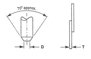
Figure 7: Formula for Estimating Electrode Tip Size (Conical Shape)
Minimum Welding Pitch
The strength of individual spot welds is determined by the spot weld pitch (the distance between spot welds). The bond between the panels becomes stronger as the pitch is shortened, but if the pitch becomes too small and the spot welds are too close together this can allow current shunting, which in effect drains away the weld current towards the previous spot weld.
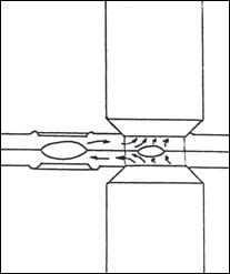
Figure 8: Current Shunting in Resistance Welds positioned in close proximity
Positioning of Welding Spot from the edge and end of the panel
The edge distance is also determined by the position of the welding tip. Even if the spot welds are normal, the welds will not have sufficient strength if the edge distance is insufficient.
Panel Thickness |
Pitch |
Margin |
0.6 |
11 |
5 |
0.8 |
14 |
5 |
1.0 |
18 |
6 |
1.2 |
22 |
7 |
1.6 |
29 |
8 |
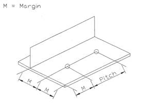
Figure 9: Welding Pitch
5.0 Electrical Power Requirements and Values Required
5.1 Power Setting
The amount of current used is very important. Too little current produces only a light tack which gives insufficient penetration. Too much current causes burned welds. Spot welds may be made one at a time or several welds may be completed at one time, depending on the number of electrodes used. With the continuous application of electrical current the joined area of the base metals melts and fuses together, as pressure is applied by the electrode tips.
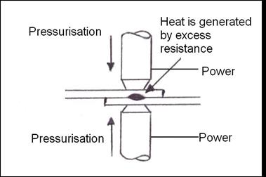
Figure 10: Current Flow
6.0 Weld Duration Requirements and Timer Settings
Timer setting is very important as it controls the junction of heat put into the spot weld. The three most important factors are current, time and pressure.
6.1 Pressure Settings
As the large electrical current flows in a concentrated area, the electrode tips apply pressure, causing the surfaces to contact.
6.2 Decanewton
One decanewton (daN) is the equivalent of one kilo of clamping force. During the welding process, if your welder is not capable of maintaining a minimum of 300daN, the molten metal will spark out, leaving a weak, porous weld. It is absolutely imperative when welding the new boron steel to have a welding gun capable of maintaining 300 daN. Boron is found mainly in the chassis sections of all new cars.
Recommended tip pressures according to the gauge of steel:
Gauge of Panel (mm) |
Pressure (kg) |
Length of Arm (mm) |
0.55 + 0.55 |
50 |
250 |
0.80 + 0.30 |
60 |
250 |
0.95 + 0.95 |
70 |
250 |
1.00 + 1.00 |
80 |
250 |
1.25 + 1.25 |
100 |
250 |
1.25 + 2.00 |
120 |
250 |
These pressures relate to HS steels: a reduction in pressure may be necessary for conventional steels.
Holding
When electrical current is stopped, the welded area gradually cools and forms a nugget. By applying pressure, the nugget’s property is made denser and its mechanical performance improves. During actual operation, these steps must be preformed without fail, as they are easy to neglect.
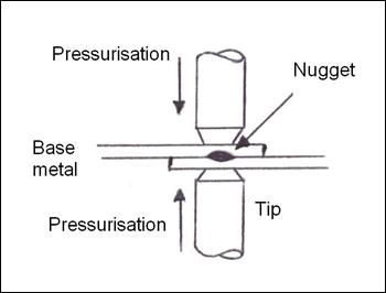
Figure 11: Spot Welding Principle
7.0 Principle of Resistance Seam Welding
7.1 Resistance Seam Welding
Seam welding is like spot welding except that the spots overlap each other, making a continuous weld seam. In this process the metal pieces pass between roller-type electrodes. As the electrodes revolve, the current supply to each one is automatically turned on and off at intervals corresponding to the speed at which the parts are set to move. With proper control it is possible to obtain air-tight and water-tight seams suitable for such parts as fuel tanks and roof panels. When spots are not overlapping long enough to produce a continuous weld, the process is sometimes referred to as roller spot or stitch welding (figure 13). In this way the work travels the distance between the electrodes required for each succeeding weld cycle. The work stops during the time required to make each individual weld and then automatically moves the proper distance for the next weld cycle. Intermittent current is usually necessary for most seam welding operations. Each individual weld contains a number of overlapping spot welds, resulting in a joint which has good mechanical strength but which is not pressure tight.
Mild steel, brass, nickel, stainless steel and many other alloys may be welded by this method, although its use is largely limited to operations on mild and stainless steel. A maximum economy is obtained if the combined thickness of the sheets to be joined does not exceed 3.2mm before welding, the surfaces must be clean and free from scale and this may be done by sand blasting, grinding or pickling.
Figure 13: Seam Welding (Stitch Welding)
8.0 Principle of Resistance Projection Welding
The welding process consists of placing the projections in contact with the mating fixtures and aligning them between the electrodes. The electrodes on the machine are not in this case bluntly pointed as in spot welding, but are usually relatively large flat surfaces which are brought to bear on the joint, pressing the projections together.
The machine can weld either a single projection or a multitude of projections simultaneously. The many variables involved in projection welding, such as thickness, kind of material and the number of projections, make it impossible to predetermine the correct current. Not all metals can be projection welded. Brass and copper do not lend themselves to this method because the projections usually collapse under pressure.
8.1 Resistance Projection Welding
Projection welding (figure 14) involves the joining of parts by a resistance welding process which closely resembles spot welding. This type of welding is widely used in attaching fasteners to structural members. This point where the welding is to be done has one or more projections which have been formed by embossing, stamping or machining. The distortion on the embossed metal face is low and is negligible on heavy metal thicknesses, although in the case of dissimilar thicknesses it is preferable to emboss the projection on the thicker of the two sheets.
9.0 Resistance Flash Welding
In the flash welding process the two pieces of metal to be joined are clamped by copper alloy dies which are shaped to fit each piece and which conduct the electric current to the work. The ends of the two metal pieces are moved together until an arc is established. The flashing action across the gap melts the metal and as the two molten ends are forced together fusion takes place. The current is cut off immediately this action is completed.
Flash welding is used to butt or mitre sheet, bar, rod, tube and extruded sections. It has unlimited application for both ferrous and non-ferrous metals. For some operations the dies are water cooled to dissipate the heat from the welded area. The most important factor to be considered in flash welding is the precision alignment of the parts. The only problem encountered in flash welding is the resultant bulge or increased size left at the point of weld. If the finish area of the weld is important, then it becomes necessary to grind or machine the joint to the proper size.
10.0 Butt Welding
In butt welding the metals to be welded are brought into contact under pressure, an electric current is passed through them and the edges are softened and fused together. This process differs from flash welding in that constant pressure is applied during the heating process, which eliminates flashing. The heat generated at the point of contact results entirely from resistance. Although the operation and control of the butt welding process is almost identical to flash welding, the basic difference is that it uses less current, has a constant pressure and allows more time for the weld to be completed. A pincer type welding gun with a powerful weld transformer (to maintain the very short weld times) is fitted with a strong pressure system to deal with the majority of work, which can be approached from two sides in pincer-type fashion. A range of interchangeable weld arms and electrodes of different shapes and lengths can be used to convert the standard gun instantly into the special tool that a job may require. Special sets of arms with electrodes, specifically designed for use on, individual makes of vehicles, have been designed in collaboration with most car manufacturers.
10.1 Spot Welder/Electric Resistant Welding
Commonly used as an alternative to riveting for jointing thin plate and light gauge metal. The spot welder has control over three adjustments, current flow, timing of weld and pressure applied. Adjustments can also be made to arms of electrode holders, to accommodate various shapes of work. Electrodes can be obtained in vertical and offset form. Electrodes are generally made of copper, for certain classes of work hey may be tipped with harder material i.e. tungsten or copper alloy. Electrodes are generally water cooled, with the water supplied through the hollow electrodes. Care should be taken when changing electrodes not to damage the tapered seating.
11.0 Setting up equipment for use
The most important point in setting up the equipment is:
The setting up procedure is as follows:
Weld Procedure
Single-sided spot welding
As a result of the operational limitations of conventional double-sided spot welding, single-sided spot welding equipment has become more widely in the vehicle body repair industry. This system offers the benefits of conventional spot welding without the inherent problems of accessibility with double skinned panel sections. Single sided spot welding is therefore an alternative to conventional double sided spot welding, or can be used in conjunction with it.
In the single sided spot welding process operating manually forces the single electrode against the panel, with the electrical circuit being completed by an earth clamp and the cable back to the transformer. This allows welds to be made in positions where access is possible only from one side.
The manufacturers are now using different types of steel to construct their vehicle bodies, the main three being low-carbon steel, galvanised steel and high-strength steel. This has led to confusion and difficulty in identification and welding. The main problem with high-strength steel is that it is heat sensitive and difficult to identify on vehicles without data. (MIRRC Thatcham Methods Manual). In double sided welding this problem is solved by using pulse welding, which keeps the heat in the weld as low as possible. Some single sided equipment especially that which operates at a high current does not require pulse control welding. Instead these machines use a massive burst of power at 8000A DC in a very short interval, which keeps the temperature of the spot weld below the recommended temperature. The other advantage of this system is that it does not need to identify whether the steel is high strength or low carbon. The problem with galvanised steel is that it has a very high contact resistance of the steel by melting the coating, causing it to flow from the weld. Then, once the resistance is low enough, it will automatically carry out the second stage weld at the correct setting.
Single sided spot welding equipment
This equipment ranges from 2500 to 1200 amperes as follows:
The equipment can be used to carry out the following operations:
Single-sided spot welding: Ideal where access is difficult from both sides of the material. It is suitable for welding on wings, front panels and rear quarter panels.
Two electrode single-sided spot welding: Suitable when unable to attach the earth clamp satisfactorily. It also allows two spot welds to be made simultaneously and is suitable for welding sill sections in place.
Pulse control roller spot welding: This gives a continuous spot weld along an overlapped edge of metal. It is ideal for roof gutters and for welding patches to vehicle panels when dealing with corrosion repair without creating distortion.
Welding copper ring washers for pulling: This allows rows of washers to be welded to the panel surface. Ideal for pulling out large dints by using a slide hammer with a special hook attachment, which fits through the rings which are later broken off by twisting.
Rapid Puller: This is designed for pulling out small dints quickly and effectively by welding the puller to the panel, pulling out the dint, then twisting the tool to release it from the panel.
Copper shrinking of high spots: this uses a copper tool for shrinking stretched panels which have been overworked by hammering.
Carbon shrinking for over stretched panel: this uses a carbon pencil rod and is used for retensioning a panel surface that is only slightly stretched.
Welding captive nuts to vehicle: this piece of equipment can be used to weld captive nuts, trim studs and threaded bolts to panel surfaces when they need to be replaced.
Single sided spot welding equipment has a low current intensity, which insures safety for the operator. The equipment uses direct current at a maximum of 12 volts. All electrodes cam be quenched in water, without danger to the operator when they become overheated, and this extends their life. Single sided welding with one electrode and one earth clamp will result in loss in the metal panel, and also the metal panel is a bad conductor of electricity.
To overcome this problem, Stanners Ltd uses a system which gives good results by using two earth clamps positioned correctly on the panels being welded. With this system 20 per cent more current is passed through the weld, resulting in better and stronger welds.
11.1 Inspection of spot welds
Spot welds are inspected either by outward appearance (visual inspection) or by destructive testing. A visual inspection is used to judge the quality of the outward appearance (tip bruises, pin holes, spatter, number of spots, spot position), while destructive testing is used to measure the strength of a weld. Most destructive tests require the use of sophisticated equipment which most body shops do not possess. Consequently a simpler method called a peel test has been developed by general use in the workshop.
11.2 Weld Testing
After setting up the equipment a test weld should be made, using sheet metal of the same thickness and condition as the job to be done. When the test piece is completed, it should be torn apart. If the settings are correct, the joint will ‘unbutton’ that is the weld
Weld tests for shear and peel for HSLA steels:
When shear testing spot welds produced when welding together two HSLA steels, partial spot weld failure may occur. If the partial failure does not exceed 20 per cent of the total nugget area the strength of the weld should not be impaired.
Principles of Destructive and Non-Destructive Tests for Resistance Spot Welding
11.3 Rectification of Weld Faults
Before making a test, check the following:
Pitting of the surface indicates that the current is being switched on before pressure is applied. To rectify, reset solenoid trip switch to give later control. A weak joint with clean surface is an indication that the pressure is too low. Increase pressure by adjusting hand nut.
Holes burned in one plate are an indication that the pressure is too high. To rectify, reduce pressure by adjusting hand nut.
Metal partially upset is an indication that the tips are not in full contact. File tips to rectify.
SPRC: Phosphorus added
SGACC, E/SGAHC: Galvanized steel plate
SGAC35R: Phosphorus added (also galvanised)
SENCE:SPCE: with electro galvanised zinc- nickel coating
No. |
Panel Types. |
Material. |
1. |
Hood panel, outer |
SGAC35R |
2. |
Hood panel, inner |
SGACC |
3. |
Upper frame, outer |
SGACC |
4. |
Upper frame, inner |
SGACC |
5. |
Front side member |
SPRC35 |
6. |
Front end gusset |
SPRC35 |
7. |
Front fender |
SENCE |
8. |
Front skirt panel |
SGACC |
9. |
Grill filler panel |
SGACC |
10. |
Front end cross member |
SPRC35 |
11. |
Site sill, inner front |
SGACC |
12. |
Front upper frame extension |
SGACC |
13. |
Cowl top outer panel |
SGACC |
14. |
Front door outer panel |
SGACC |
15. |
Front door inner panel |
SGACE |
16. |
Rear door outer panel |
SGACC |
17. |
Rear door inner panel |
SGACE |
18. |
Roof panel |
SGACC |
19. |
Front pillar, outer, lower |
SPRC35 |
20. |
Front pillar, outer, upper |
SPRC35 |
21. |
Front pillar, inner, upper |
SPRC35 |
22. |
Centre pillar, inner |
SPRC35 |
23. |
Centre pillar, outer |
SPRC35 |
24. |
Front floor, side sill, outer |
SGACC |
25. |
Front floor, side sill, inner |
SGACC |
26. |
Side sill, outer rear extension |
SGACC |
27. |
Quarter panel, inner |
SENCE |
28. |
Rear pillar, inner |
SPRC35 |
29. |
Rear shelf panel |
SPRC35 |
30. |
Trunk lid inner panel |
SGACE |
31. |
Trunk lid outer panel |
SGAC35R |
32. |
Quarter panel, outer |
SENCE |
33. |
Rear skirt panel |
SGACC |
34 |
Rear floor cross member |
SGACC |
35. |
Rear floor side member |
SGACC |
36. |
Rear floor side sill |
SGACC |
37. |
Roof reinforcement |
SGAHC |
Summary
The three qualities a spot weld must achieve:
The replacement welds, adhesives etc. shown on the welding diagrams are denoted by the following symbols:
Spot Weld |
|
Spot Welds (Hidden or obscured) |
|
MIG Plug Welds |
|
MIG Plug Welds (Hidden or obscured) |
|
MIG Seam Weld |
|
MIG Seam Weld (Hidden or obscured) |
|
Seam & Plug Welds |
|
Adhesive |
|
‘Bulk’ cuts (panel removal) |
|
Source: http://local.ecollege.ie/Content/APPRENTICE/liu/vbr_notes/m1u4.doc
Web site to visit: http://local.ecollege.ie
Author of the text: indicated on the source document of the above text
If you are the author of the text above and you not agree to share your knowledge for teaching, research, scholarship (for fair use as indicated in the United States copyrigh low) please send us an e-mail and we will remove your text quickly. Fair use is a limitation and exception to the exclusive right granted by copyright law to the author of a creative work. In United States copyright law, fair use is a doctrine that permits limited use of copyrighted material without acquiring permission from the rights holders. Examples of fair use include commentary, search engines, criticism, news reporting, research, teaching, library archiving and scholarship. It provides for the legal, unlicensed citation or incorporation of copyrighted material in another author's work under a four-factor balancing test. (source: http://en.wikipedia.org/wiki/Fair_use)
The information of medicine and health contained in the site are of a general nature and purpose which is purely informative and for this reason may not replace in any case, the council of a doctor or a qualified entity legally to the profession.
The texts are the property of their respective authors and we thank them for giving us the opportunity to share for free to students, teachers and users of the Web their texts will used only for illustrative educational and scientific purposes only.
All the information in our site are given for nonprofit educational purposes