
GENERAL
PURPOSE
The sawing machine is a machine tool designed to cut material to a desired length or contour. It functions by drawing a blade containing cutting teeth through the workpiece. The sawing machine is faster and easier than hand sawing and is used principally to produce an accurate square or mitered cut on the workpiece.
The power hacksaw and the bandsaw are two common types of sawing machines used to cut metal in the machine shop. The power hacksaw uses a reciprocating (back and forth) cutting action similar to the one used in a hand hacksaw. The power hacksaw is used for square or angle cutting of stock. The band saw uses a continuous band blade. A drive wheel and an idler wheel support and drive the blade.
All power hacksaw machines are basically similar in design. Figure 6-1 shows a typical power hacksaw and identifies its main parts, which are discussed below.
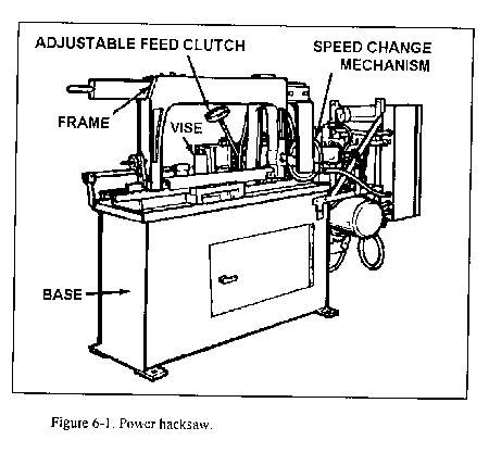
Base
The base of the saw usually contains a coolant reservoir and a pump for conveying the coolant to the work. The reservoir contains baffles which cause the chips to settle to the bottom of the tank. A table which supports the vise and the metal being sawed is located on top of the base and is usually referred to as part of the base.
Vise
The vise is adjustable so that various sizes and shapes of metal may be held. On some machines the vise may be swiveled so that stock may be sawed at an angle. The size of a power hacksaw is determined by the largest piece of metal that can be held in the vise and sawed.
Frame
The frame of the saw supports and carries the hacksaw blade. The machine is designed so that the saw blade contacts the work only on the cutting stroke. This action prevents unnecessary wear on the saw blade. The cutting stroke is on the draw or back stroke.
Some machines feed by gravity, the saw frame having weights that can be shifted to give greater or less pressure on the blade. Other machines are power fed with the feed being adjustable. On these machines, the feed is usually stopped or reduced automatically when a hard spot is encountered in the material, thus allowing the blade to cut through the hard spot without breaking.
The shift lever allows the number of strokes per minute to be changed so that a variety of metals may be sawed at the proper speeds. Some saws have a diagram showing the number of strokes per minute when the shift lever is in different positions; others are merely marked "F," M," and "S" (fast, medium, and slow).
The adjustable feed clutch is a ratchet-and-pawl mechanism that is coupled to the feed screw. The feed clutch may be set to a desired amount of feed in thousandths of an inch. Because of the ratchet-and-pawl action, the feed takes place at the beginning of the cutting stroke. The clutch acts as a safety device and permits slippage if too much feed pressure is put on the saw blade. It may also slip because of a dull blade or if too large a cut is attempted. This slippage helps prevent excessive blade breakage.
Metal-cutting bandsaw machines fall into two basic categories: vertical machines (Figure 6-2) and horizontal machines (Figure 6-3). Band saws use a continuous saw blade. Chip removal is rapid, because each tooth is a precision cutting tool and accuracy can be held to close tolerances eliminating or minimizing many secondary machining operations.
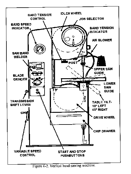
The metal-cutting vertical band sawing machine, also called a contour machine, is made in a variety of sizes and models by several manufacturers. The size of a contour machine is determined by the throat depth, which is the distance from the saw band to the column. Figure 6-2 shows a typical contour machine and identifies its main parts, which are discussed below.
The variable speed unit is located within the base of the machine. This unit consists of two V-type pulleys which are mounted on a common bearing tube. A belt on one pulley is driven by the transmission, while the belt on the other pulley drives the saw band drive wheel. The two outside cones of the pulleys are fixed, but the middle cone is shifted when the speed change wheel is turned. A shift in the middle cone causes the diameter of one pulley to increase and the diameter of the other pulley to decrease. This slowly changes the ratio between the two pulleys and permits a gradual increase or decrease in the speed of the machine.
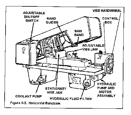
The horizontal band sawing machine does the same job as the power hacksaw but does it more efficiently. The blade of the bandsaw is actually a continuous band which revolves around a drive wheel and idler wheel in the band support frame. Two band guides use rollers to twist the band so that the teeth are in the proper cutting position. The guides are adjustable and should be adjusted so that they are just slightly further apart than the width of the material to be cut. This will give maximum support to the saw band and help assure a straight cut.
The vise on the horizontal bandsaw is much like the one on the power hacksaw. However, the horizontal bandsaw has a much greater capacity for large stock than does the power hacksaw. The stationary jaw can be set at several angles. The movable jaw adjusts automatically to whatever position the stationary jaw is in when the vise handwheel is tightened.
The horizontal bandsaw is operated hydraulically by controls on a control box, which is located on the front side of the machine. A motor and pump assembly supplies hydraulic fluid from a reservoir in the base to a cylinder, which raises and lowers the support arm and also controls the feed pressure and band tension. A speed and feed chart is sometimes provided on the machine, but when it is not, consult the operator's manual for the proper settings for sawing.
A coolant pump is located in one of the legs of the base, which serves as a coolant reservoir. The coolant cools the saw band and also washes away chips from the cut before they can clog the band.
Sawing machines have some special safety precautions that must be observed. These are in addition to those safety precautions described in Chapter 1. Here are some safety precautions that must be followed:
Power hacksaw blades differ from hand hacksaw blades in that they are generally heavier, made in longer sizes, and have fewer teeth per inch. Hacksaw blades are discarded when they become dull; sharpening is not practical.
Materials commonly used in manufacturing power hacksaw blades are high-speed tungsten steel and high-speed molybdenum steel. On some blades only the teeth are hardened, leaving the body of the blade flexible. Other blades are hardened throughout.
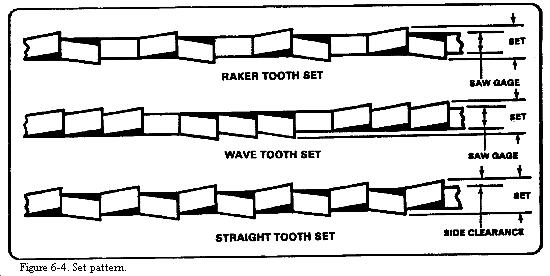
The set is the amount of bend given the teeth. The set makes it possible for a saw to cut a kerf or slot wider than the thickness of the band back (gage), thus providing side clearance.
This is the pattern in which the teeth are set. There are three set patterns: raker, wave, and straight, as shown in Figure 6-4.
The pitch of hacksaw blade teeth (Figure 6-5) is expressed as the number of teeth per linear inch of blade. For example, a blade having 10 teeth per inch is said to be 10 pitch.
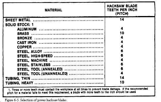
Power hacksaw blades are coarser in pitch (fewer teeth per inch) than hand hacksaw blades. Common pitches for power hacksaw blades range from 4 to 14 teeth per inch.
The following are guidelines for the selection of power hacksaw blades.
Figure 6-5 is provided to assist in the proper selection oxf power hacksaw blades. Note that sheet metal and tubing are listed separately from solid stock. It is assumed that solid stock will be sufficiently thick that three or more teeth will be in contact with the stock at all times.
General
Bandsaw blades are manufactured in two forms. They are supplied in rolls of 50 to 500 feet for use on machines that have butt welders for forming their own blade bands. Bandsaw blades are also supplied in continuous welded bands for machines having no provisions for welding.
Materials
Bandsaw blades are made from special alloy steels. The blades are made flexible by annealing the body of the blade and hardening only the teeth.
Set
Metal cutting bandsaw blades have their teeth bent (Figure 6-4). This bend produces a kerf slightly wider than the thickness of the blade, which prevents the blade from being pinched by the stock. There are three set patterns: raker, wave, and straight, as shown in Figure 6-4.
Pitch
The pitch of bandsaw blades is expressed as the number of teeth per linear inch of the blade. Metal cutting blades range from 6 to 32 teeth per inch, the coarser tooth blades being used for sawing large stock and soft metals.
Selection of Bandsaw Blades
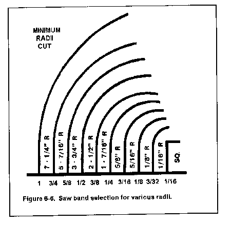
Select bandsaw blades according to the type of material to be cut, the thickness of the material to be cut, and the sawing operation to be performed. Always use the widest and thickest saw band possible. However, consider the curvature of the cut, since wide saw blades cannot cut sharp curves. Figure 6-6 shows saw band selection for various radii.
For general sawing, use the raker set pattern. The wave set pattern is used where thin work sections are encountered during the cut, such as tubing, angles, and channels.
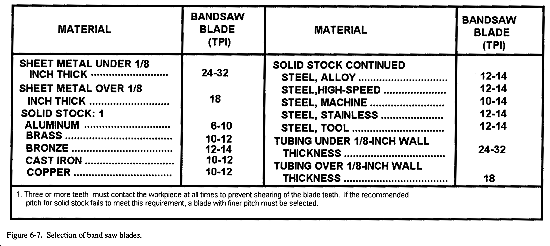
Three teeth of the bandsaw blade must be in contact with the workpiece at all times to prevent chatter and shearing off teeth. Therefore, use fine tooth blades to cut sheet metal and tubing. If the sheet metal is too thin to meet this requirement with the finest tooth blade available, place the metal between plywood, fiberboard, or thicker metal. Figure 6-7 is a guide for selecting the proper pitch band saw blade for different metals and metal thickness.
The finish depends largely upon the saw pitch. The faster the saw speed and the finer the sawpitch, the finer the finish. Lubricating helps to improve the finish. A fine saw pitch, high velocity, and light feed produce the finest finish.
Bandsaw Blade Wear
Bandsaw blades naturally become dull from prolonged use, but some conditions promote greater than normal wear on the blades. Blades dull quickly if used at too high a speed for the material being cut. Also, if the material to be cut is too hard for the pitch of the blade, abnormal wear will result. The most common cause of premature blade dulling occurs from using too fine a pitch blade and from feeding too heavily.
The following symptoms indicate a dull bandsaw blade. When these symptoms are noticed, the blade should be replaced.
The bandsawing machine is adapted for filing by use of the band file attachment. A band file is fitted over the drive and idler wheels and in place of the bandsaw blade. The band is made up of several parts or segments which are riveted at one end (the leading end) to a spring steel band. The trailing end of each segment is free to lift during the time when the band bends over the drive and idler wheels of the band saw. When the band straightens out, the segments lock together. Figure 6-8 shows the construction of and terminology for file band parts.
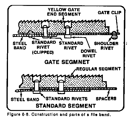
Note that the gate segment (a segment at one end of the band that is specially designed to allow the two band ends to be locked together) has a shoulder rivet and a dowel rivet protruding from beneath it. The shoulder rivet locks into the other file band end, and the dowel rivet aligns the two end segments and prevents the shoulder rivet from sliding out of the locked position during filing. The gate segment of a file band is identified by yellow paint.
Cut of File Teeth
File bands are either coarse or bastard cut and normally range in pitch from 10 to 20 teeth per inch. The coarse 10-pitch bands are used for filing softer metals such as aluminum, brass, copper, and cast iron. A bastard-cut 14-pitch band is a good choice for general steel filing, while 16 to 20 pitch bastards are recommended for filing tool steel.
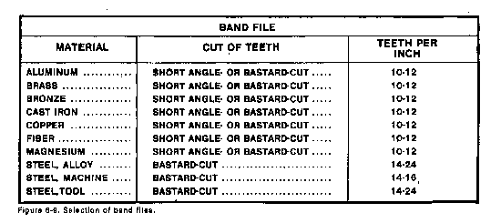
Selection of Band Files
Choose band files on the basis of workpiece thickness and type of material to be filed. In general, the thicker the workpiece, the coarser the file should be. This is due to a larger chip accumulation from the larger area of the workpiece, thus requiring additional space for the chips between the teeth. On thin sheet metal, a fine pitch file is required to prevent chatter. Use fine pitch files for filing tough carbon and alloy steels; use coarser pitch files for filing softer metals. Figure 6-9 is provided to aid in selecting the proper file for filing specific materials.
Care and Cleaning of Band Files
Clean the file often, using a stiff brush or a file card. Move the brush in the direction of each cut of the file to dislodge all particles hidden between the teeth.
The file band should not be coiled into more than three loops. The best means of storing file bands is in a cabinet looped over a 16-inch radius support with the ends hanging free.
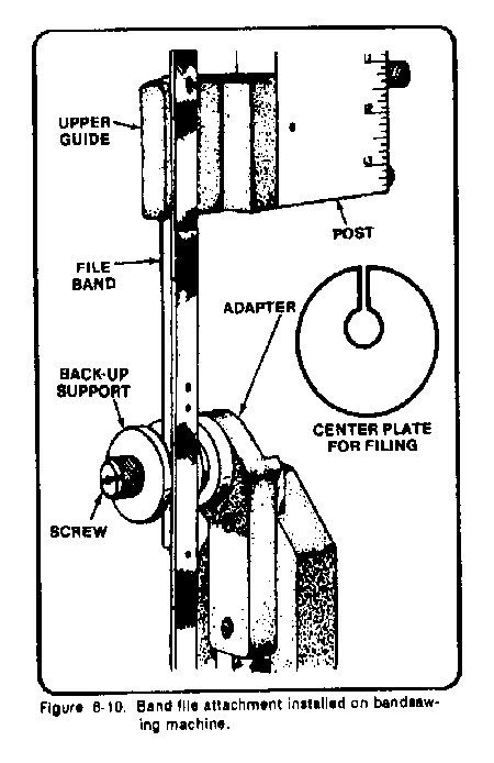
Band File Attachment
A band file attachment (Figure 6-10) is provided with most bandsaw machines to permit the use of band files. A typical band file attachment consists of a band file guide and upper and lower guide supports that attach to the frame and part of the band saw. A special filing filler plate is provided to adapt the table slot to the extra width and depth required for the band file and file band guide.
Polishing can be performed on the bandsaw using a polishing attachment and polishing band. The polishing band is usually 1 inch wide and has a heavy fabric backing.
Types of Polishing Bands
Polishing bands for bandsawing machines are usually supplied in various grain sizes of aluminum-oxide or silicone carbide abrasive: No 50 grain (coarse) for heavy stock removal and soft material, No 80 (medium) for general surface finishing, and No 120 or No 150 grain (fine) for high polishing and light stock removal.
Selection of Polishing Bands
Polishing bands should be selected according to the particular job to be performed. For removing tool marks and deburring edges, use the No 50 grain polishing band. Finer grain polishing bands should not be used on soft metals like aluminum or cast iron because the band will quickly fill with metal particles, reducing the cutting action
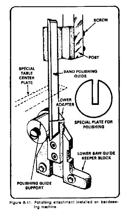
Polishing Attachment
The polishing attachment (Figure 6-11), similar to the band file attachment, provides support for the polishing band. The polishing band plate acts as a solid backing for the polishing band to prevent stretching and distorting the band when the workpiece is held against it. Use a polishing band filler plate to fill the table slot so the workpiece can be supported close to the polishing band.
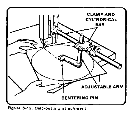
Use the disc-cutting attachment (Figure 6-12) to saw internal or external circles and discs. The diameter of the circle that can be cut is limited to the length of the cylindrical bar on the attachment or to the throat depth of the machine. The disc-cutting attachment consists of three main parts a clamp and cylindrical bar, which is fastened to the saw guidepost; an adjustable arm, which slides on the cylindrical bar; and a pivot or centering pin. The disc must be laid out and center-drilled to a depth of 1/8 inch to 3/16 inch to provide a pivot point for the centering pin. The centerline of the centering pin must be in line with the front edge of the sawteeth and at the desired distance from the saw band.
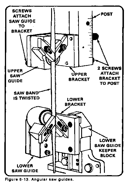
This attachment (Figure 6-13) twists the blade so that long workpieces that would not normally clear the machine column can be cut. The blade is twisted to a 30 degree angle on most machines.
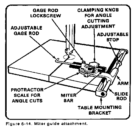
A typical miter guide attachment is illustrated in Figure 6-14. The workpiece is supported against the miter head which attaches to the slide arm. The attachment can be set at an angle with a protractor, using the table slot as a reference line. A gage rod can be extended from the attachment and used as a stop when identical lengths are sawed. When not in use, swing the attachment on the slide rod so that it hangs below the table.
Layout
Power hacksaw machines are primarily intended for straight line cutting of stock to specific lengths. Laying out the workpiece consists of measuring the length to be cut and indicating the position for the cut by scribing a line on the stock.
Mounting
Before mounting the stock to be cut, the vise should be checked for squareness with the hacksaw blade. Place a machinist's square against the blade and the stationary vise jaw. Adjust the jaw, if necessary, at 90° to the blade. If the workpiece is to be cut at an angle other than 90°, loosen the vise and swivel it to the desired angle, measuring the angle carefully with a protractor.
Stroke
Move the blade frame and hacksaw blade by hand through one draw stroke and one return stroke. Observe whether the stroke is centered on the work and if the blade holders will clear the workpiece at the end of the stroke. Readjust the position of the vise if the stroke is not centered on the workpiece. Shorten the stroke if the blade holders hit the workpiece at the end of each stroke.
Stop gage
Use a stop gage to speed up mounting stock when several pieces of the same length are to be cut. Mount the first piece in the vise and align with the hacksaw blade to cut at the scribed line, When the workpiece is correctly positioned, move the stop gage up to the end of the workpiece and lock it in place. Cut subsequent pieces by moving the stock up to the stop gage and clamping the workpiece in the vise at this position.
The vise must be securely tightened on the workpiece to prevent loosening during cutting. Blade breakage might result from shifting workpieces not clamped tightly in the vise.
The stock should be measured and the position of the cut machinist's square or a protractor against the bandsaw blade and the stationary vise jaw. Position the stock in the vise so that the saw blade aligns with the scribed line on the stock. If. more than one piece is to be cut to the same size, move the stock stop arm against the end of the stock and lock it in place. Additional pieces can then and moved up against the stop to produce pieces equal in length to the first piece
When laying out workpieces for vertical bandsawing operations, consider the size of the stock in relation to the clearance of the bandsaw machine column. For straight-line sawing the clearance is easy to judge, but for contour sawing of large size stock, the directions of cut must be carefully figured to prevent the stock from hitting the column. If a small section is to be cut from a large sheet of metal, the section should be roughly cut oversize from the sheet and then carefully cut to the prescribed outline.
When a circle or disk is to be sawed using the disk cutting attachment, lay out the circle on the stock as follows:
When an outline to be cut consists of more than two intersecting lines, the following procedure should be followed.
Efficient sawing with sawing machines requires sharp saw blades in good condition. To prevent dulling and breakage of saw blades, proper speeds and feeds must be maintained. The speed of the saw blade for any specific operation depends upon the nature of the material being cut.
Power hacksawing machines cut by drawing the hacksaw blade toward the motor end of the machine. At the completion of this movement called the draw stroke, the hacksaw blade is lifted slightly to clear the material being cut and moved an equal distance in the opposite direction.
Mounting Workpieces
Workpieces for metalcutting machines are not mounted to the machine, but are supported by the table of the machine and guided by one of the sawing machine attachments or by hand.
Power Hacksaw Speeds.
Since the cutting speed of hacksawing machines is measured in strokes per minuet, the length of the stroke is an important consideration. A longer stroke at a given speed will cut faster than a shorter stroke at the same speed. Thus. to obtain a proper cutting speed the length of the stroke must be specified.
The length of the stroke of most power hacksaws is between 4 and 10 inches depending upon the size of the machine. On machines with an adjustable stroke, the wider the stock being cut, the shorter the stroke to prevent the blade holders from hitting the stock.
With most power hacksaws, the stroke length is adjustable within 2 or 3 inches. and on some machines more than one speed can be selected. On single-speed hacksawing machines, the speed must be regulated by changing the stroke.
If the stroke is doubled the machine will cut twice as fast, and if the stroke is decreased by one-half, the machine will cut half as fast. This proportion can be applied to any fraction to increase or decrease the cutting speed of the machine.
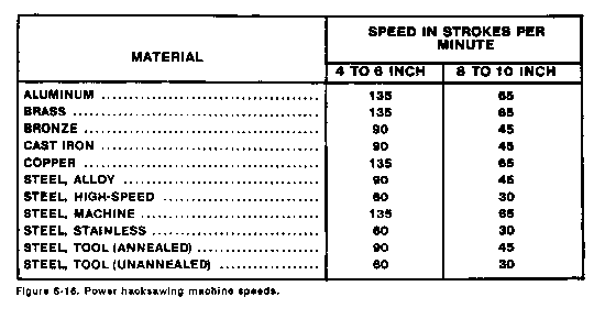
The speeds given in the chart, Figure 6-16, bellow are for example only. The correct speeds for cutting various metals will depend on the type of machine you are using. In general the faster speeds are used for cutting soft materials and the slower speeds are used for cutting harder materials. If a recommended speed cannot be approximated either by changing the stroke or changing the speed, the feed can be decreased to prevent undue wear to the hacksaw blade.
Power hacksaw machines having a mechanical feed can usually be regulated to feed the saw downward from 0.001 to 0.025 inch per stroke, depending upon the type and size of the material to be cut. On these machines, a device to stop the feed when hard spots are encountered is usually incorporated into the design.
The feed of machines having gravity feed is regulated by the weight of the saw frame and any additional weights or springs that might be connected or attached to the frame to increase or decrease the downward force of the hacksaw blade. Maximum and minimum blade pressures obtainable are determined by the manufacturer of the hacksawing machine, and are specified as relatively light or heavy.
The following general rules apply for selecting proper feeds for hacksawing machines:
The cutting speed of the bandsaw machine is the speed of the bands blade as it passes the table measured in feet per minute. The feed of the horizontal band saw machines downward pressure applied to the material being cut by the bands blade. The feed of vertical bandsawing machines is the pressure applied to the bands blade by the material being cut.
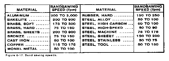
Bandsawing Speeds
Proper bandsaw speeds are important in conserving bands blades. Too great a speed for the material being cut will cause abnormally rapid blade wear, while too slow a speed will result in inefficient production. The chart of recommended speeds (Figure 6-17) are guidelines only. It shows the speeds for a given type of machine. The cutting speed always depends on the type of machine you are using and the manufactures' recommendations.
All bandsawing machines have several cutting speeds. Since the diameter of the drive wheel of the bandsaw machine establishes a fixed ratio between the motor or transmission speed in RPM to the blade speed in FPM, it is not necessary to convert RPM into FPM as with most other machine tools. The speeds are identified in FPM on the sawing machine speed selector controls. Some machines have a speed indicator so a careful check of sawing speeds may be made when the machine is operating with or without a load.
In general the following principles apply to speeds of bandsaw blades:
Horizontal Bandsawing Machine Feeds
Feed of horizontal bandsaw machines is controlled by adjusting the pressure applied by the saw blade against the material being cut, as with hacksawing machines.
The horizontal saw has a spring counterbalance and a sliding weight to adjust the pressure of the blade. When the sliding weight is moved toward the pivot point of the saw frame the band saw blade pressure is reduced. When the weight is moved away from the pivot point, the pressure is increased.
The following general principles apply when regulating the feed of horizontal band saw machines.
Vertical Machine Feeds
With vertical machines, the feed is the pressure applied to the saw blade by the material being cut. The workpiece may be hand fed or power fed depending upon the operation to be performed. Cutting curves or special contours requires that the workpiece be guided and fed into the saw blade by hand.
The power feed on bandsaw machines is operated by adjustable weights in the machine pedestal. The weights are connected by cables to one of the work-holding attachments of the sawing machine to pull the workpiece against the bandsaw blade. To operate the power feed, the weights are raised by depressing a pedal and the cables are then fixed to the work-holding attachment. When the pedal is released the weights pull the piece into the blade.
The following general rules apply to feeding workpieces on bandsawing machines:
Most sawing machines used in military operations are dry cutting machines; that is, they are not intended for use with liquid coolants. However, some power hacksaws and horizontal bandsaws are equipped with a coolant attachment. Soluble oil products, when mixed with water to form emulsions, are used for these machines. This type of coolant has proven very satisfactory for sawing where cooling is an important factor. Most manufacturers of water oil emulsion coolants add a rust inhibitor to the solution to prevent rusting caused by the water in the coolant.
Straight-line sawing is the most common machine sawing operation. It may be performed using the power hacksaw, horizontal, or vertical band saw.
Power Hacksawing
The power hacksaw machine is designed primarily for straight-line sawing. A typical sawing operation is outlined below:
Horizontal Bandsawing
Like hacksawing machines, the horizontal bandsaw machine is used primarily for straight-line sawing. The typical sequence of operation for this machine is outlined next.
Vertical Band Saw Operation
Straight-line sawing is performed on the vertical band saw machine by using one or a combination of several mechanisms or attachments: the miter guide attachment, with or without power feed, with or without the work-holding jaw device-. and the work-holding jaw device with power feed and angular blade guide attachment.
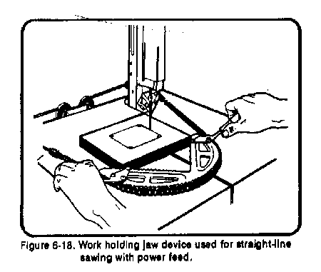
A typical example of straight-line sawing is outlined below :
Radius sawing is performed on the bandsaw by either guiding the workpiece by hand or by using the disk-cutting attachment.
Blade Selection
Care must be taken to select a bandsaw blade of the proper width for the radius or circle to be cut. If the blade is too wide for the radius, the heel of the blade will press against the outer edge of the kerf (Figure 6-19). When the heel contacts this edge, any further twisting of the workpiece in an attempt to cut a sharper radius will twist the bandsaw blade and may result in the blade breaking.
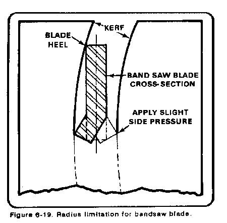
Cutting Pressure
When cutting a radius, apply a slight side pressure at the inner cutting edge of the bandsaw blade (Figure 6-19). This pressure will give the blade a tendency to provide additional clearance.
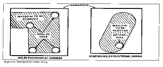
Contour sawing is the process of cutting shapes in which the direction of the cut must be changed at intervals. Holes larger in diameter than the width of the saw blade must be drilled at each corner where a change of direction of the bandsaw blade will occur. Figure 6-20 illustrates the methods of changing direction of a cut at a hole.
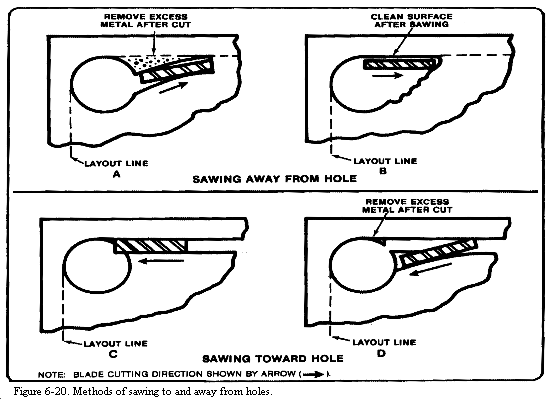
Sawing Away From the Hole
To saw away from the hole on a line tangent to the hole, the saw blade must cut away from the center of the hole, or the blade will bow and cause a belly in the cut. The cut should be started as in A, Figure 6-20, in which a curve is cut outward from the hole to meet the layout line, leaving a piece of excess metal which can be removed later by filing. An alternate method is shown at B, Figure 6-20, in which a section of metal is notched out with a saw blade by several short cuts to give the blade clearance for starting the cut along the layout line.
Sawing Toward the Hole
The diagrams at C and D, Figure 6-20, show the proper method of sawing up to a hole in two cuts. The excess metal can be removed later by filing. After the shape is cut and the slug or waste material is removed, the comers should be finished by filing or notching. The bandsaw blade should not be used for these operations because the blade will bow and cut unevenly.
Internal sawing is performed in the same manner as contour sawing except that the bandsaw blade cannot start cutting from the edge of the workpiece but must start cutting from a drilled hole in the workpiece (Figure 6-20). With the pattern laid out on the workpiece and the starting hole drilled, insert an unwelded bandsaw blade of the proper length through the starting hole. Bring the two ends of the blade together at the butt welder of the bandsawing machine and weld the blade into a continuous band as described in the pertinent operation manual for the machine. Install the bandsaw blade on the sawing machine and make the necessary adjustments to the machine. With the cut starting from the hole as shown in A or B, Figure 6-20. When the sawing is completed, cut the bandsaw blade so that it can be removed from the workpiece.
Filing is performed on the vertical band saw machine using a band file and the band file attachment. As with sawing, the quality of filing and the economical wear of the band file depend upon proper selection of files and filing speeds for different materials and conditions.
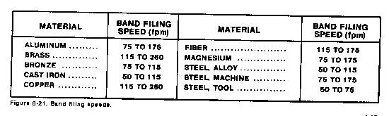
Band Filing Speed
Band files should be run at relatively slow speeds as compared to speeds used for band sawing. Figure 6-21 lists recommended speeds for band filing. Note that, in general, the slower speeds are used for filing harder metals and faster speeds are used for filing softer metals.
Band Filing Feeds
Work pressure on the band file should not be excessive. A medium amount of pressure applied against the band file moving at the proper speed will produce curled chips which will not clog the file. Heavy pressure will cause clogging and can cause the file to break or the machine to stall. A light pressures should be used for finish filing, with a slow, sideways motion that will not leave vertical file marks on the workpiece.
Polishing bands and a polishing attachment are provided with the vertical band saw machine so that light polishing can be performed. The polishing bands are intended primarily for removing saw marks on the cut edges of workpieces.
Polishing Speeds
Move polishing bands at speeds between 75 and 260 FPM, the faster speeds being used for softer materials and the slower speeds being used for harder materials.
Polishing Feeds
Feeds should be light for polishing. Use a slow, sideways motion s
Source: http://faculty.ksu.edu.sa/hossainy/Book1/Chapter%206.doc
Web site to visit: http://faculty.ksu.edu.sa/
Author of the text: indicated on the source document of the above text
If you are the author of the text above and you not agree to share your knowledge for teaching, research, scholarship (for fair use as indicated in the United States copyrigh low) please send us an e-mail and we will remove your text quickly. Fair use is a limitation and exception to the exclusive right granted by copyright law to the author of a creative work. In United States copyright law, fair use is a doctrine that permits limited use of copyrighted material without acquiring permission from the rights holders. Examples of fair use include commentary, search engines, criticism, news reporting, research, teaching, library archiving and scholarship. It provides for the legal, unlicensed citation or incorporation of copyrighted material in another author's work under a four-factor balancing test. (source: http://en.wikipedia.org/wiki/Fair_use)
The information of medicine and health contained in the site are of a general nature and purpose which is purely informative and for this reason may not replace in any case, the council of a doctor or a qualified entity legally to the profession.
The texts are the property of their respective authors and we thank them for giving us the opportunity to share for free to students, teachers and users of the Web their texts will used only for illustrative educational and scientific purposes only.
All the information in our site are given for nonprofit educational purposes