
Slab Design
The slab design for 601 New Jersey Avenue was the major factor in the design of other structural members, the building’s cost and the final architecture of the building. The floor framing system that was used to replace the existing system is a two-way concrete slab. This type of slab construction was implemented in the sub grade garage levels of the existing building. However a separate design was formulated for the office layers above as mentioned in the existing conditions portion of this report to provide longer spans and an open office space. The change to concrete permitted the reduction of the floor-to-floor height by 14 inches. The accumulations of these heights over nine floors of the building permitted the addition of tenth floor to the office space, adding approximately 28,500 square feet. However at the same time this system did not process the same spanning capabilities of the steel system. As a result columns were placed strategically in the space to help support the slab as well as allow for adequate passage of vehicles in the sub grade garage.
The primarily focus of this design is to determined the feasibility of the use of a two-way concrete system through the design of the slab in typical areas of the building. Spans in the north south direction of the structure were maintained to avoid a change in the façade of the structure. The spans on the east west sides of the structure were changed slightly to accommodate the design of the slab and to provide a more consistence layout to aid in the design of the structure. ADOSS was the primarily means to which this slab was designed. Hand calculations were also performed to determine the accuracy of the ADOSS results. Each will be discussed in further detail in the following paragraphs.
ADOSS DESIGN:
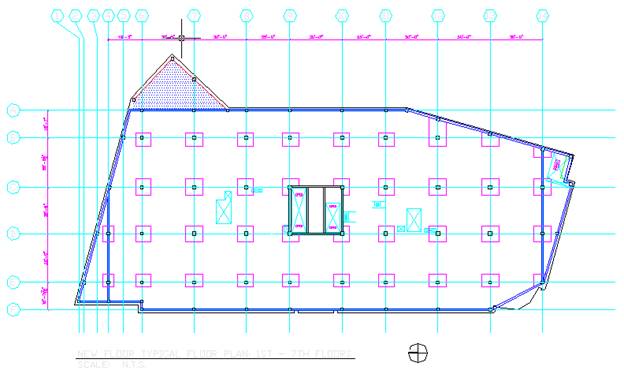
The ADOSS program was first used as a preliminary means of determining the required depth of the concrete slab. Several runs of this program were performed Once a slab depth was determined the results of the joint moments were found for the design of the vertical members of the structure. However a preliminary layout was designed for the building and can be found in the figure below as well as Appendix A.1 of this report at a larger scale.
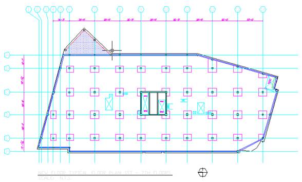
Because of the uneven span lengths and diagonal sides of the structure, many preliminary calculations were performed in order to enter the layout into ADOSS. These calculations will be discussed in this portion of the report because of relevance to the ADOSS input. The following paragraphs will outline the steps taken to determine to arrange this design.
Six representative strips of the new layout were analyzed as typical spans of the building. They consisted of three horizontal and three vertical sections. The figure below illustrates the location of the sample slabs that were used for the analysis of 601 New Jersey Avenue.
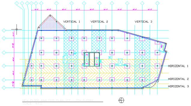
For vertical one, there were no changes in the layout that had to be made before its dimensions could be inputted into ADOSS, but for the other five sample areas several assumptions had to be made in order to use ADOSS for this analysis. These assumptions will be discussed individually for each sample analysis area. And finally the design of the buildings edge beam will be reviewed as well. Nonetheless the results for the vertical one sample area are listed below.
|
VERTICAL ONE |
|||||
|
NEGATIVE REINFORCEMENT |
|||||
|
COLUMN STRIP |
MIDDLE STRIP |
||||
Column Number |
Long Bars |
Short Bars |
Long Bars |
|||
no. |
size |
no. |
size |
no. |
size |
|
1 |
5 |
# 4 |
4 |
# 4 |
23 |
# 4 |
2 |
6 |
# 7 |
5 |
# 7 |
23 |
# 4 |
3 |
10 |
# 6 |
10 |
# 6 |
20 |
# 4 |
4 |
10 |
# 6 |
10 |
# 6 |
19 |
# 4 |
5 |
6 |
# 7 |
5 |
# 7 |
23 |
# 4 |
6 |
5 |
# 4 |
4 |
# 4 |
23 |
# 4 |
|
POSITIVE REINFORCEMENT |
|||||||
|
COLUMN STRIP |
MIDDLE STRIP |
||||||
Span Number |
Long Bars |
Short Bars |
Long Bars |
Short Bars |
||||
no. |
size |
no. |
size |
no. |
size |
no. |
size |
|
2 |
5 |
# 4 |
4 |
# 4 |
12 |
# 4 |
11 |
# 4 |
3 |
12 |
# 4 |
11 |
# 4 |
8 |
# 4 |
8 |
# 4 |
4 |
11 |
# 4 |
11 |
# 4 |
9 |
# 4 |
8 |
# 4 |
5 |
11 |
# 4 |
11 |
# 4 |
8 |
# 4 |
8 |
# 4 |
6 |
5 |
# 4 |
4 |
# 4 |
12 |
# 4 |
11 |
# 4 |
Horizontal One:
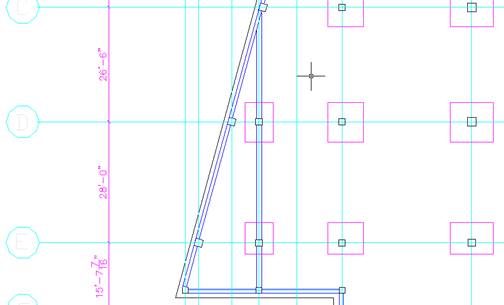
There were two issues that had to be addressed before this sample span could be inputted into ADOSS. The design of this area was a two-step process, due to several issues had to be addressed. They include the following:
These issues were addressed by two different methods. First the slanted edge was estimated as a straight edge by taking a straight line though the centerline of the exterior column this is illustrated below.

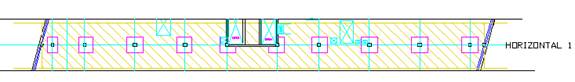
Thus the slab was estimated as a straight line for the purpose of determining the reinforcing on the internal spans of the structure. This area was relatively representative of the actual area of the slab. However, by doing this, the slab now puts a uniform torque on the adjacent slab when previously it was more prominent of the lower half of the slab.
The second problem that arose for the ADOSS input was the significantly smaller span length found at the edge of this same sample area. This is apparent in the drawing above. The exterior column and the first interior column, in this case, are 6.229 feet apart. The span adjacent to this is 19.25 feet. A simple solution to uneven span lengths could be to take out the middle column; this may be possible for the upper lying areas or near the centerline of the columns. But as the wall moves away as you proceed down, the span length becomes increasingly larger. At times spanning more than 30 feet. This span length was too large for the design of the slab, because of the need to conserve the structural space that the slab occupies. Thus the column was retained in its position, still permitting the passage of occupants between it and the exterior wall. These outer lying areas, because of their high width to length ration they were then designed as a one-way slab. These calculations are further discussed in the manual calculation section of this report.
To solve these problems, two cases for the Horizontal One design were developed. In the first Horizontal one case, the exterior span was left on the structure but it was cantilevered from the adjacent span. The span length that was used was the equivalent span length discussed previously. This in turn produced the worst negative moment that could act on the last two-way slab span. The wall and edge beam loads were calculated and added as a dead load on this cantilever span with the superimposed loads. Live loads were also placed on this cantilever slab. The calculations for these loads can be found in Appendix A.1 of this report. They are the gray slab, and brown slab. Where the gray slab is on the north side of the building and the brown slab is on the southern portion of the structure.
For the second case the structure was entered into ADOSS without these smaller spans. Thus producing the worst positive moments condition to the adjacent span. The weights for the wall and edge beam were neglected for this case because they would in effect reduce the positive moment in the slab. After these cases were entered into the ADOSS program the worse case moment reinforcing of the two cases were used for the design of this slab. Overall the results from ADOSS came out as expected, case one was the controlling for the negative reinforcement and case two controlled for the positive reinforcement as anticipated. The finally reinforcement of this sample is shown in the charts below.
HORIZONTAL ONE FINAL |
||||||
|
NEGATIVE REINFORCEMENT |
|||||
|
COLUMN STRIP |
MIDDLE STRIP |
||||
Column Number |
Long Bars |
Short Bars |
Long Bars |
|||
no. |
size |
no. |
size |
no. |
size |
|
1 |
6 |
# 5 |
6 |
# 5 |
20 |
# 4 |
2 |
7 |
# 7 |
6 |
# 7 |
20 |
# 4 |
3 |
12 |
# 6 |
12 |
# 6 |
23 |
# 4 |
4 |
10 |
# 6 |
10 |
# 6 |
20 |
# 4 |
5 |
11 |
# 6 |
10 |
# 6 |
22 |
# 4 |
6 |
11 |
# 6 |
10 |
# 6 |
22 |
# 4 |
7 |
11 |
# 6 |
10 |
# 6 |
20 |
# 4 |
8 |
12 |
# 6 |
11 |
# 6 |
22 |
# 4 |
9 |
12 |
# 6 |
12 |
# 6 |
18 |
# 5 |
10 |
9 |
# 6 |
9 |
# 6 |
16 |
# 4 |
|
POSITIVE REINFORCEMENT |
|||||||
|
COLUMN STRIP |
MIDDLE STRIP |
||||||
Span Number |
Long Bars |
Short Bars |
Long Bars |
Short Bars |
||||
no. |
size |
no. |
size |
no. |
size |
no. |
size |
|
2 |
7 |
# 4 |
7 |
# 4 |
10 |
# 4 |
10 |
# 4 |
3 |
9 |
# 5 |
8 |
# 5 |
9 |
# 4 |
8 |
# 4 |
4 |
9 |
# 5 |
9 |
# 5 |
9 |
# 4 |
9 |
# 4 |
5 |
9 |
# 4 |
8 |
# 4 |
9 |
# 4 |
8 |
# 4 |
6 |
9 |
# 5 |
9 |
# 5 |
10 |
# 4 |
9 |
# 4 |
7 |
9 |
# 4 |
8 |
# 4 |
9 |
# 4 |
8 |
# 4 |
8 |
9 |
# 5 |
9 |
# 5 |
9 |
# 4 |
9 |
# 4 |
9 |
11 |
# 4 |
11 |
# 4 |
8 |
# 4 |
8 |
# 4 |
10 |
11 |
# 5 |
10 |
# 5 |
11 |
# 4 |
10 |
# 4 |
Horizontal Two:
This sample had similar characteristics of the Horizontal One sample slab, except that the north portion of this slab was assumed straight without a cantilever design. The southern portion of the slab however was cantilevered in case one and then removed in case two. The results for these two cases were reviewed and the worst case reinforcing was chosen for the slab. These values were also very consistent with the expected values for this slab design, and they can be viewed below.
HORIZONTAL TWO FINAL |
||||||
|
NEGATIVE REINFORCEMENT |
|||||
|
COLUMN STRIP |
MIDDLE STRIP |
||||
Column Number |
Long Bars |
Short Bars |
Long Bars |
|||
no. |
size |
no. |
size |
no. |
size |
|
1 |
4 |
# 4 |
4 |
# 4 |
17 |
# 4 |
2 |
6 |
# 4 |
6 |
# 4 |
17 |
# 4 |
3 |
7 |
# 6 |
7 |
# 6 |
15 |
# 4 |
4 |
10 |
# 6 |
9 |
# 6 |
18 |
# 4 |
5 |
8 |
# 6 |
7 |
# 6 |
15 |
# 4 |
6 |
8 |
# 6 |
8 |
# 6 |
16 |
# 4 |
7 |
8 |
# 6 |
8 |
# 6 |
16 |
# 4 |
8 |
8 |
# 6 |
7 |
# 6 |
14 |
# 4 |
9 |
8 |
# 6 |
8 |
# 6 |
19 |
# 4 |
10 |
8 |
# 7 |
7 |
# 7 |
15 |
# 5 |
11 |
9 |
# 5 |
9 |
# 5 |
13 |
# 4 |
|
POSITIVE REINFORCEMENT |
|||||||
|
COLUMN STRIP |
MIDDLE STRIP |
||||||
Slab Number |
Long Bars |
Short Bars |
Long Bars |
Short Bars |
||||
no. |
size |
no. |
size |
no. |
size |
no. |
size |
|
2 |
4 |
# 4 |
4 |
# 4 |
9 |
# 4 |
8 |
# 4 |
3 |
5 |
# 4 |
5 |
# 4 |
8 |
# 4 |
7 |
# 4 |
4 |
10 |
# 4 |
10 |
# 4 |
7 |
# 4 |
6 |
# 4 |
5 |
10 |
# 4 |
9 |
# 4 |
7 |
# 4 |
6 |
# 4 |
6 |
6 |
# 4 |
6 |
# 4 |
7 |
# 4 |
7 |
# 4 |
7 |
7 |
# 5 |
6 |
# 5 |
7 |
# 4 |
7 |
# 4 |
8 |
6 |
# 4 |
6 |
# 4 |
7 |
# 4 |
7 |
# 4 |
9 |
10 |
# 4 |
9 |
# 4 |
7 |
# 4 |
6 |
# 4 |
10 |
8 |
# 4 |
8 |
# 4 |
7 |
# 4 |
6 |
# 4 |
11 |
9 |
# 5 |
8 |
# 5 |
9 |
# 4 |
8 |
# 4 |
Horizontal Three:
There were several assumptions made for the design of this analysis area. The first was the use of a consistent slab even for indented or circular portions of the structure, as can been seen in the picture below.
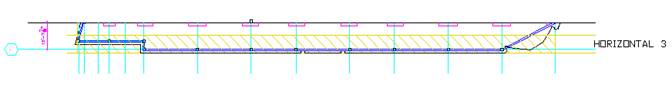
As a result a cantilever is formed at the southern end of the structure. Ideally it was thought that this area would be cantilevered in the new structure, and this provides a conservative estimate of the load that this area will impose on the other systems of the structure. However this area was not designed in depths for this analysis. The edge beam runs underneath this area, which will help to support the torsion loads that this cantilever would impose on the structure. Nonetheless further analysis would have to be explored to determine how much deflection might be found in this area, which might have to be addressed with the addition of columns.
The results for Horizontal three could not be calculated through ADOSS for this particular analysis. Due to time limitations and unexpected complications the required reinforcement for these areas are not included in this report. However from these results the moments on the columns could be estimated for the purpose of completing that portion of the report. This will be further discussed in the column design portion for this report.
Vertical Two:
This portion of the slab was analyzed because of its proximity to the elevator lobby of this floor. Because of the large about of concrete that will have to be removed from this bay it is no longer a two way slab, but a one way slab with beams and girders. The girders act as an edge beam for this system in the analysis even though it does not act on the entire length of this system. This was the only way that this system could be modeled in ADOSS in this particular case. Overall it produced reasonable results.
|
VERTICAL TWO |
|||||
|
NEGATIVE REINFORCEMENT |
|||||
|
COLUMN STRIP |
MIDDLE STRIP |
||||
Column Number |
Long Bars |
Short Bars |
Long Bars |
|||
no. |
size |
no. |
size |
no. |
size |
|
1 |
5 |
# 4 |
4 |
# 4 |
23 |
# 4 |
2 |
6 |
# 8 |
5 |
# 8 |
23 |
# 4 |
3 |
10 |
# 5 |
10 |
# 5 |
16 |
# 4 |
|
POSITIVE REINFORCEMENT |
|||||||
|
COLUMN STRIP |
MIDDLE STRIP |
||||||
Slab Number |
Long Bars |
Short Bars |
Long Bars |
Short Bars |
||||
no. |
size |
no. |
size |
no. |
size |
no. |
size |
|
2 |
5 |
# 4 |
4 |
# 4 |
12 |
# 4 |
11 |
# 4 |
3 |
10 |
# 5 |
9 |
# 5 |
10 |
# 4 |
10 |
# 4 |
Vertical Three:
For the third vertical section, some of the same concepts from the Horizontal one sample were implemented. The edges for both the east and west ends of the structure were assumed to be a straight line, so that these values could be analyzed by ADOSS.
|
VERTICAL THREE |
|||||
|
NEGATIVE REINFORCEMENT |
|||||
|
COLUMN STRIP |
MIDDLE STRIP |
||||
Column Number |
Long Bars |
Short Bars |
Long Bars |
|||
no. |
size |
no. |
size |
no. |
size |
|
1 |
14 |
# 4 |
13 |
# 4 |
17 |
# 4 |
2 |
9 |
# 7 |
9 |
# 7 |
28 |
# 4 |
3 |
12 |
# 5 |
12 |
# 5 |
20 |
# 4 |
4 |
6 |
# 7 |
5 |
# 7 |
25 |
# 4 |
5 |
5 |
# 4 |
4 |
# 4 |
25 |
# 4 |
|
POSITIVE REINFORCEMENT |
|||||||
|
COLUMN STRIP |
MIDDLE STRIP |
||||||
Column Number |
Long Bars |
Short Bars |
Long Bars |
Short Bars |
||||
no. |
size |
no. |
size |
no. |
size |
no. |
size |
|
2 |
12 |
# 5 |
11 |
# 5 |
12 |
# 4 |
12 |
# 4 |
3 |
8 |
# 4 |
8 |
# 4 |
10 |
# 4 |
9 |
# 4 |
4 |
12 |
# 4 |
11 |
# 4 |
9 |
# 4 |
9 |
# 4 |
5 |
5 |
# 4 |
4 |
# 4 |
13 |
# 4 |
12 |
# 4 |
Edge beam:
The design of the edge beam was first estimated and placed in the samples that were explored above. The dimensions of the edge beam are 17.5 inches by 12 inches and were found to be sufficient for the slab designs. Because this beam is on the outer lying edge of the structure the beam has more floor to floor space because of the absence of heating and air-conditioning ducts. The reinforcement in the edge beam varies on its position on the structure. These values were not addressed for this report due to time limitations.
From this analysis, it was determined that a 10.5 inch slab was necessary for the stability of the two-way concrete slab system. The 10.5 inch slab was needed primarily on the analysis section on column line 13. This portion of the building is unique from other portions of the structure in that there is a 30 foot bay on both sides of it, being a 30 foot bay itself. All other portions of the slab were able to substance their respective loads with a 9.5 inch slab however due to this area, a consistent slab depth was used. The deflections for these spans were also acceptable according to ACI.
MANUAL CALCULATIONS:
After that the required depth was obtained from the ADOSS analysis the slab was then checked to determine the accuracy of the modeling process due to the unusual shape the of the building. Several of the outer lining edges of the slab had to be designed manually. In addition the one-way slab portion of the structure, at the elevator lobby and at some of the outlaying edges of the slab, these designs were also conducted manually. First we will look at the check done to the overall ADOSS analysis then we will address the one-way slab portions that were designed for this new system.
Verification of ADOSS Results:
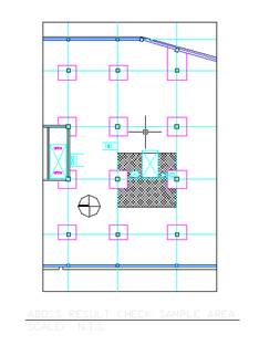 Because of the odd shape and uneven span lengths direct design method could not be implemented for the design of this system. However the equivalent beam method for this project is very extensive and time consuming. ADOSS was very useful in designing the majority of the sections of the structure. It was uncertain if the values from ADOSS would be accurate because of the odd shape of the building and the assumptions made for the input of the structure into the program. An easy method of verifying that the values obtained for this analysis were accurate was through hand calculations using the direct design method. The only limitation to this method was that only the core area of the building could be analyzed. In addition there could be some inaccuracies of this method compared to the equivalent frame method because of the outer spans of the structure. Nonetheless the method was less tedious and time consuming.
The part of the slab that was analyzed was in the near the core of the building. If this portion of the slab were alone in the structure it would meet all the requirements of the direct design method. This check will focus specifically o n the three bays between column lines 11 and 12 and about column line D. This analysis area is shown above. From this check it was determined that the ADOSS results were correct for the structure. All the values were similar or above the steel areas found through the direct design check. The differences that that arise may be due do the fact that this method is not appropriate for this building. Nonetheless the fact that the ADOSS values were consistently above the hand calculations was encouraging. The calculations, sample layouts and comparison of the different methods are found in Appendix A.1 of this report.
One Way Slab Calculations:
There were two primary areas where one-way design was used, in the elevator lobbies and on the outside edge of the structure. The elevator area was building with a 5.5 inch slab and two beams that run in the east west direction of the building. The slab and these beams were designed for this analysis, however the north south beams were omitted to the complexity of this connection to the two-way slab and time limitation of this analysis. A layout of this area can be found below in and the calculations for this slab can be found in Appendix A.1 of this report. On the outside edges of the structure there are many spans that do not meet
CONCLUSION:
It was assumed that this system would be feasible for the design of this system because of its use in the garage levels of the structure. There were some complications in the design of this slab, however overall reasonable values were obtained for the reinforcing of the slab. The hand calculations provided a means for determining the accuracy of the ADOSS results however due the odd shape and irregular spans of the structure these calculations required the use of the equivalent frame methods, as apposed to the direct design method, which is more time consuming. The benefits and disadvantages of the slab system are found below.
INCOUNTERED BENEFITS OF SYSTEM:
INCOUNTERED DISADVANTAGES OF SYSTEM:
Source: http://www.engr.psu.edu/ae/thesis/portfolios/2003/alh237/Slab%20Design.doc
Web site to visit: http://www.engr.psu.edu
Author of the text: indicated on the source document of the above text
If you are the author of the text above and you not agree to share your knowledge for teaching, research, scholarship (for fair use as indicated in the United States copyrigh low) please send us an e-mail and we will remove your text quickly. Fair use is a limitation and exception to the exclusive right granted by copyright law to the author of a creative work. In United States copyright law, fair use is a doctrine that permits limited use of copyrighted material without acquiring permission from the rights holders. Examples of fair use include commentary, search engines, criticism, news reporting, research, teaching, library archiving and scholarship. It provides for the legal, unlicensed citation or incorporation of copyrighted material in another author's work under a four-factor balancing test. (source: http://en.wikipedia.org/wiki/Fair_use)
The information of medicine and health contained in the site are of a general nature and purpose which is purely informative and for this reason may not replace in any case, the council of a doctor or a qualified entity legally to the profession.
The texts are the property of their respective authors and we thank them for giving us the opportunity to share for free to students, teachers and users of the Web their texts will used only for illustrative educational and scientific purposes only.
All the information in our site are given for nonprofit educational purposes