
 Total Runout
Product requirement
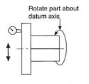
The total runout must not exceed 0.06 at any point measured across the entire surface parallel to the datum axis.
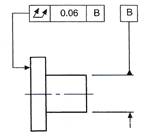
Drawing instruction
Note: The symbol ![]() means that the measuring instrument is guided across a theoretically exact surface true to the datum axis.
means that the measuring instrument is guided across a theoretically exact surface true to the datum axis.
A positional tolerance controls the location of one feature from another feature or datum.
The tolerance zone can be the space between two parallel lines or planes, a circle, or a cylinder. The zone defines the permissible deviation of a specified feature from a theoretically exact position.
The tolerance value is the distance between the parallel lines or planes, or the diameters of the circle or cylinder.
The theoretically exact position also incorporates squareness and parallelism of the tolerance zones with the plane of the drawing.
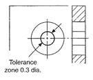
 Case 1
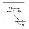
Product requirement
The point must be contained within a circle of 0.1 diameter in the plane of the surface. The circle has its centre at the intersection of the two theoretically exact dimensions. If the point were to be located by three dimensions, the tolerance zone would be a sphere.
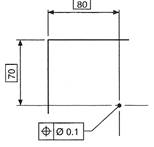
Drawing instruction
 Product requirement
The axis of the hole must be contained in a cylindrical tolerance zone of 0.3 diameter with its axis coincident with the theoretically exact position of the hole axis.
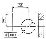
Drawing instruction
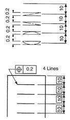 Case 3
Product requirement
Each line must be contained between two parallel straight lines on the surface, 0.2 apart, which are symmetrical with the theoretically exact positions of the required lines.
Drawing instruction
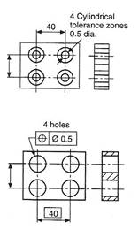 Case 4
Product requirement
The axes of each of the four holes must be contained in a cylindrical tolerance zone of 0.5 diameter, with its own axis coincident with the theoretically exact position of each hole.
Drawing instruction
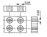 Product requirement
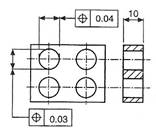 The axes of each of the four holes must be contained in a boxed zone of 0.04 x 0.03 x 10, symmetrically disposed about the theoretically exact position of each hole axis.
Drawing instruction
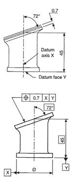
Product requirement
The angled surface must be contained between two parallel planes 0.7 apart, which are symmetrically disposed about the theoretically exact position of the surface relative to datum axis X and datum face Y.
Drawing instruction
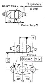
Product requirement
The axes of the two holes must be contained in cylindrical tolerance zones of 0.01 diameter, with their own axes coincident with the theoretically exact hole positions related to datum face X and the datum centre-line axis Y.
Drawing instruction
The characteristics to which it can be applied are as follows:
The characteristics to which the maximum material condition concept cannot be applied are as follows:
Figure 1 shows a typical drawing instruction where limits of size are applied to a pin, and in addition a straightness tolerance of 0.2 is applicable at the maximum material condition.

Figure 1
Figure 2 shows the condition where the pin is finished at the maximum material condition with the maximum straightness error. The effective assembly diameter will be equal to the sum of the upper limit of size and the straightness tolerance.
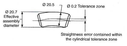
Figure 2
The straightness error is contained within a cylindrical tolerance zone of Ø0.2.
To provide the same assembly diameter of 20.7 as shown in Figure 3 when the pin is finished at its low limit of size of 20.0, it follows that a straightness error of 0.7 could be acceptable. This increase may in some cases have no serious effect on the function of the component, and can be permitted.
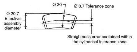
Figure 3
Figure 4 shows a typical drawing instruction where limits of size are applied to a pin, and in addition a squareness tolerance of 0.3 is applicable at the maximum material condition.
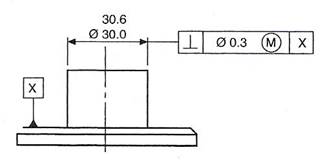
Figure 4
Figure 5 shows the condition where the pin is finished at the maximum material condition with the maximum squareness error of 0.3. The effective assembly diameter will be the sum of the upper limit of size and the squareness error. The squareness error will be contained within a cylindrical tolerance zone of Ø0.3.
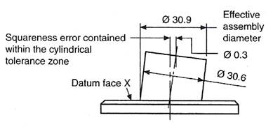
Figure 5
To provide the same assembly diameter of 30.9, as shown in Figure 6, when the pin is finished at its low limit of size of 30.0, it follows that the squareness error could increase from 0.3 to 0.9. This permitted increase should be checked for acceptability.
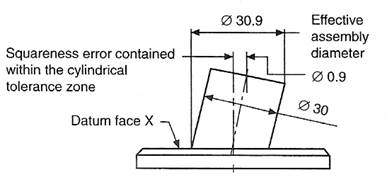
Figure 6
A typical drawing instruction is given in Figure 7, and the following illustrations show the various extreme dimensions which can possibly arise.
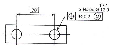
Figure 7
Condition A (Figure 8)
Minimum distance between hole centres and the maximum material condition of holes.
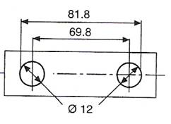
Figure 8
Condition B (Figure 9)
Maximum distance between hole centres and maximum material condition of holes
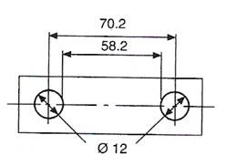
Figure 9
Condition C (Figure 10).
To give the same assembly condition as in A, the minimum distance between hole centres is reduced when the holes are finished away from the maximum material condition.
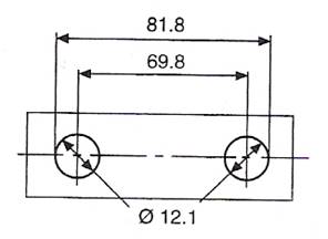
Figure 10
Condition D (Figure 11)
To give the same assembly condition as in B, the maximum distance between hole centres is increased when the holes are finished away from the maximum material condition.
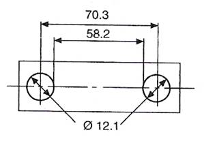
Figure 11
Note that the total tolerance zone is 0.2 + 0.1 = 0.3, and therefore the positional tolerance can be increased where the two holes have a finished size away from the maximum material condition.
One of the biggest breakthroughs in this area has been the progress made in non-destructive testing (NDT). Powerful X-ray equipment or the use of radioactive isotopes enable us to look right inside and examine the results on a film in much the same way as a surgeon would examine a medical X-ray (Figure 12).
Figure 12 - X-Ray Inspection
Ultrasound (pulses of high-frequency sound) can also be used (Figure 13). When the equipment is used by a skilled operator it can produce information about the quality of a structure without the stringent safety precautions required for the use of X-rays and radioactive isotopes (Figure 14).
Figure 13 - Ultrasonic Inspection
Figure 14 - On-Site Inspection of Node Joint using Ultrasonic Equipment
Miniature television cameras are often used to inspect the penetration of welds in small-diameter pipes.
Special dyes are employed in the dye penetrant test. These dyes will find their way into any surface defects and highlight them on subsequent inspection as, after the work has been wiped, the dye will remain in the defect. Some dyes are fluorescent in ultraviolet light.
Magnetic particle inspection works in a similar way, when oil containing iron powder is spread over the area and the work magnetised. The particles will gather around any surface or near surface defect (Figure 15).
Figure 15 - Magnetic Particle Inspection
Use in a well ventilated area; never spray on a hot surface.
Many of these tests (such as the bend test and tensile test) will fail if there are internal defects present. Other tests, such as the nick break test, break open the weld so that we can see inside it. The macro-etch test will show fusion faces and internal defects.
Figure 16 - Butt Weld Specimen Prepared for a Nick Break Test
If there is a fault in the structure, the bend test will probably reveal it by failure of the specimen.
Figure 17 - Principle of the Bend Test
Figure 18 - Destructive Tests used to check Spot Welding Procedure
Having looked at the structure of materials in general, we now need to look more closely at the structure of metals, and at what happens when metals are welded. This will help you to appreciate the care that is needed when you are performing welding operations, and why you have to use different techniques and procedures with different metals.
However, first we need to look at the overall properties of metals, so that we can understand how these properties are affected by the details of the structure.
Different metals have different mechanical properties. These properties determine how metals behave in use. The mechanical properties of interest to the engineer are described below.
A ductile metal is one that can be easily drawn into a rod or a wire (Figure 19). A metal's ductility is determined by the amount it will stretch, lengthwise, before it becomes brittle and fails.
For a metal to be ductile, the molecules must have a great attraction for each other after the yield point has been passed. As the molecules have a greater attraction for each other when cold, metals will be more ductile when cold. This is why wires and rods for the welding industry are drawn in the cold state.
This measures a metal's ability to be formed into a specified shape without fracturing, and to remain in that shape once the load has been removed. Plasticity usually increases with rise in temperature. Very few metals are plastic in the cold state, so heat is normally used when forming, to increase plasticity. For example, iron and steel are difficult to bend when cold, but bend easily when red hot. There are odd exceptions to this, when an increase in temperature can cause brittleness (see below) in some metals. Wrought iron, for example, is plastic, but can sometimes break (because of impurities) when red-hot.
This is the opposite of plasticity. It refers to a metal's tendency to break suddenly when under load, without any appreciable deformation. Many metals in their cast state will fracture when subjected to a large enough impact. In some metals, an increase in temperature can reduce brittleness, while in others it can increase it. For example, copper is a ductile metal, but it becomes brittle near its melting point. In general, most metals become less brittle when you apply heat to them. You should take special care when welding brittle metals, because of their lack of ductility.
Figure 19 - Wire needs to be ductile in order to be drawn through a die
This property allows a metal to be compressed without failure. The metal can therefore be permanently flattened or stretched by hammering or rolling. The more malleable a metal is, the thinner the sheets into which it can be formed. Metals, such as iron and steel, become much more malleable with increased temperature. Copper is very malleable except near its melting point. Zinc is only malleable between 140°C and 160°C. Any impurities will reduce malleability. A rivet needs to be made of a malleable material in order to withstand the hammering.
Here is a list of some metals in order of decreasing malleability:
Figure 20 - Tensile Strength
This is usually defined as a metal's ability to resist indentation or abrasion. The measurement of hardness is usually based on a metal's resistance to the indentation of either a hardened steel ball (the Brinell hardness test) or a diamond (the Vickers or Rockwell hardness tests). Abrasion tests are sometimes used, as in the shot- and sand-blasting industries, for example.
Hardness can be increased by deformation caused by cold working. This is known as work hardening. In steels, carbon is the main hardening element, and in many ferrous alloys high levels of hardness can be obtained by heating the alloy to a high temperature followed by rapid cooling.
This measures a metal's ability to withstand a stretching load without breaking (Figure 20). Another name for tensile strength is tenacity.
This is a combination of ductility and tenacity. It is the property that enables a material to resist fracture by bending, twisting or shock.
This is the property that enables a metal to withstand compressive loading without fracture (Figure 21).
Figure 21 - Compressive Strength
This measures a metal's ability to withstand loads that are not in the same line of force (offset loads) (Figure 22).
Figure 22 - Shear Strength
This measures a metal's ability to withstand impact (Figure 23).
Figure 23 - Impact Strength
This measures a metal's ability to deform under load and then return to its original shape once the load has been removed. A spring is a good example of elasticity.
A tensile testing machine is specially designed to pull specimens of specified dimensions to breaking point in order to determine some of the metal's properties.
When the specimen is under tensile stress and the load is gradually increased until breaking point occurs, then the specimen will pass through certain phases. These phases can be shown by plotting a stress-strain curve. The curve is found by taking a number of load (Figure 24) shows a typical stress-strain curve for a ductile material such as low-carbon steel. From A to B, the straight line indicates that the extension is proportional to the load. Between these points, the material still retains its elasticity, so that if the load is removed the specimen will return to its original length.
Figure 24 - Stress-Strain Curve for a Ductile Material
If the extension (strain) is proportional to the applied load (stress), the metal is said to have obeyed Hooke's law.
For example, if the stress increases by 50 per cent, the strain will also increase by 50 per cent, producing a straight line, which will indicate the elastic range of the material.
Stress = Load
cross-sectional area
Strain = Extension of gauge length
Original gauge length
Hooke's law = Stress = E
Strain
where E is a constant known as Young's modulus.
From B to C, the metal extends with no increase in load. The specimen is said to have taken permanent set; if the load is removed at this stage, the metal will not return to its original length. This is known as the yield point.
From C to D the extension is no longer proportional to the load. If the load is removed, little or no spring-back will occur. In this stage the metal is said to be plastic.
Point D is the ultimate tensile stress of the material and point E represents the breaking point (or fracture point). From D to E the material appears to continue stretching under reduced load. In fact, the specimen, because it is a ductile material, is thinning out (necking), until it finally breaks at point E.
To calculate the ultimate tensile strength (UTS) of the metal, the maximum load indicated on the stress-strain curve (D) is divided by the original cross-sectional area. The UTS is mainly of use at the design stage.
The yield stress is calculated by taking the load at point B and dividing by the original cross-sectional area of the specimen. It is usual for designers to work at 50 per cent of this figure to give a 'safety factor'.
The elongation percentage is found by taking the increased length at fracture and dividing it by the original length. The resulting figure is expressed as a percentage and is an accurate indication of the material's ductility.
Figure 25 - Comparing the Failure of a Ductile Specimen and a Brittle Specimen after Loading
A brittle material will show little or no 'necking' and will fracture in a brittle manner, usually with a bang (Figure 25). Figure 26 compares the stress-strain curve for a high-carbon steel with that of a low-carbon steel. It shows that the carbon steel:
Figure 26 - Comparing the Stress-Strain Curves of High-Carbon Steel and Low-Carbon Steel
This comparison shows that an increase in hardness will normally produce an increased tensile strength, but a reduction in ductility.
For certain welding tests, specimens can be machined entirely from weld metal. Figure 27 shows an example of an all-weld-metal specimen. In this specimen:
Gauge length = 5.65 Öcross-sectional area
= 5.65 Ö78. 55
= 5.65 x 8.862
= 50
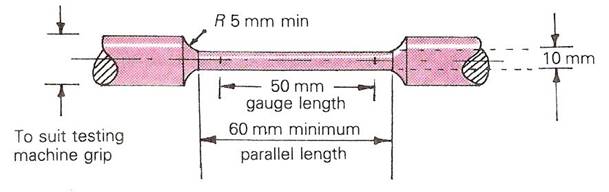
Figure 27 - An All-Weld-Metal Test Specimen
Figure 28 shows an example of a tensile test specimen including plate material and weld. Depending on the code, sections 1 and 3 can be used for tensile specimens, and sections 2 and 4 can be used as bend test specimens.
Always check exact dimensions of tensile specimens against the requirements of the welding code or standard that you are working to.
Figure 28 - Tensile Test Specimen Including Plate Material and Weld
There are three main types of structure into which metallic elements (metals) crystallise. The three space lattice patterns in Figure 29 show graphical representations of the orderly geometric patterns into which the atoms arrange themselves on cooling from the liquid to the solid state.
Figure 29 - Three Main Types of Lattice Structure into which Metallic Materials Arrange Themselves
The body-centred cubic structure has nine atoms, one at each corner of the cube and one at the centre. This crystal pattern is found in such metals as iron, molybdenum, chromium, tungsten and vanadium.
The face-centred cubic structure, as its name implies, has an atom in the centre of each face. Typical metals with this space lattice pattern are aluminium, copper, nickel, lead, platinum, gold and silver.
The close-packed hexagonal structure is more tightly packed than the first two. Cadmium, bismuth, magnesium, cobalt, titanium and zinc are among the metals that have this type of crystalline structure.
Generally, metals with the face-centred lattice structure are ductile, plastic and workable. Metals with the body-centred structure have higher strength with lower cold-working properties. Metals with the close-packed hexagonal lattice lack plasticity and cannot be cold worked.
In a pure metal, these individual crystals will start to form at many centres (or nuclei) throughout the cooling material. The process starts with one unit of the crystal lattice and rapidly builds up with the addition of atoms and lattice structures into a crystal framework called a dendrite (Figure 30).
Figure 30 - Stages of Crystallisation as a Metal Solidifies
(Viewed under a microscope)
From the dendrite, arms of space lattices start to grow in other directions, giving an appearance similar to a fir tree with the growth of its twigs and branches. The dendrite is sometimes called a fir tree crystal because of this.
As the temperature continues to fall, the dendrite increases in size until its arms come into contact with other similar structures. At this point growth stops in that direction and solidification begins to take place between the arms of the dendrite. This solidification continues until the crystal is formed. Normally there is no trace of the original dendrite.
However, if impurities have been trapped between the dendrite arms, or if the metal has cooled too rapidly, metal may not have fed completely into the spaces between dendrites. This will cause shrinkage cavities and allow the outline of the dendrite to be visible.
The rate at which a metal cools will affect the number of nuclei formed; slow cooling will promote the growth of fairly few nuclei. The result is that the crystals (or grains) will be large enough to be visible without the aid of a microscope. Fast cooling will promote many nuclei and a small fine-grain structure.
In a large ingot of cast metal or a large weld, the crystal sizes can vary considerably from the outer edges to the centre (Figure 31). This is due to variation in the temperature gradient, because as an ingot (or a large weld) solidifies, heat will be transferred from the metal to the mould (or the heavy parent material).
Figure 31 - An Ingot of a Pure Metal Showing the Crystal Structure
(Viewed under a microscope)
When the metal first makes contact with a cold mould there is a chilling effect and many small crystals form. As the mould warms up, the direction of cooling is mainly inwards and extremely elongated columnar crystals are formed. As heat is lost still further, the metal in the centre begins to form its own nuclei and a third type of crystal is formed, showing no preference for directional growth. These central crystals are much larger than the chilled crystals at the outer edges, because of their slower rate of cooling. These central crystals are known as equiaxed, because they have no preference for directional cooling.
The deformation of grains can have a big effect on the mechanical properties of a metal. Deformation can take place when a metal is being cold worked during operations such as hammering, pressing, rolling, drawing or bending. An example of how crystals can become greatly elongated and strain hardened is shown in Figure 32 where a plate is undergoing a cold-rolling operation.
This undesirable structure can be rectified by applying enough heat to produce the growth of new equiaxed crystal grains, which will return the structure to an unstrained state with the same properties that it had before the cold working took place.
The temperature at which these new grains form is called the recrystallisation temperature. It is important to hold the metal at this temperature just long enough for the new grains to form, and then to control the cooling rate so that the structure will consist of the refined equiaxed crystals. If the metal is subjected to too much heating above its recrystallisation point, grain growth can occur. These weaker enlarged grains can also be formed if the cooling rate is too slow. Such enlarged grains can decrease ductility and tensile strength, but these properties could, of course, be restored by correct recrystallisation treatment.
Figure 32 - Cold Rolling of a Steel Plate
(Viewed under a microscope)
Stresses on Metals
Figure 33 - Forces
Accuracy in metalwork is essential if the designed artefacts are to work satisfactorily. To produce good-quality workpieces, you therefore need to take great care in marking out, measuring and inspecting. Tools meant for these processes should form part of the equipment in the metal workshop of every institution.
Before you can shape or form workpieces, you have to mark them to the required dimensions. The following tools are used in marking out.
You use the scriber, which has a hardened tool-steel tip, in conjunction with the try square to mark lines at right angles to or parallel to an angle. There are many patterns of scriber (Figure 34). The bent-end scriber can be used in awkward positions.
Figure 34 - Scribers
Figure 35 - Using the Scriber
Figure 36
The combination set (Figure 38) is an important tool in the workshop, because you can use it as a centre square, a try square and a protractor for marking out, measuring and testing. There are three heads (protractor, square and centre), which slide onto a rule, which can be fixed at any position using the nut provided.
Figure 37 - Setting Dividers: a) Firm-Jointed Type; b) Spring-Controlled Type
Figure 38 - Combination Set
The main parts of the combination set are used as follows.
You can obtain detailed dimensions of workpieces using measuring tools such as the rule, or the combination set. You can also test existing features (such as holes) for accuracy using inspection tools such as plugs and gauges.
Figure 39 - Using the Combination Set: a) Try Square; b) Centre Square; c) Protractor
Figure 40 - Using the Surface Gauge
a) Set the scriber.
b) Hold the work against the angle plate and move the block against the work.
Figure 41 - Using the Vee Block
There are several types of H.S.F.G. bolt (Figure 42), but all must be tightened to the specified minimum tension.
Figure 42 - High Strength Friction Grip Bolts
The term H.S.F.G. relates to bolts of high tensile steel, used in conjunction with high tensile steel nuts and hardened steel washers. They are tightened to a predetermined shank tension in order that the clamping force thus provided will transfer loads in the connecting members by friction between the parts and not by shear in, or bearing on, the bolts or plates of connecting members.
These bolts are made by a special cold working process which includes two operations: heading and thread rolling. Figure 43 shows the head for identification. Close tolerances ensure accuracy, and heat treatment is carried out afterwards.

Figure 43 - Bolt Head
ISOM = ISO metric identification; XYZ = manufacturer’s (trade) marking; 601 = strength grade
The surfaces in contact must be free from paint, oil, dirt, loose rust and scale. Each bolt is assembled with one washer in cases where plane parallel surfaces are involved. The washer is placed under the bolt head or nut, whichever is to be rotated during the tightening operation. A tapered washer must be used also if the angle is above 3°.
Driving of bolts is not permitted.
If, after final tightening, a nut or bolt is slackened off, it must not be used again.
Higher grade (waisted shank) bolts BS 4604 may be used in joints subject to tension as well as shear, using the part turn method of tightening. Tightening by the torque control method is not permitted.
Used on road bridges, structural repairs and extensions, heavy installations subject to vibration, power station work and colliery winding gear.
H.S.F.G. bolts have virtually replaced hot driven rivets for fastening steel structures on site. They are also used to replace defective rivets on repair work.
Where structural members are shop assembled, welding is still more economical on the whole, but certain connections are better bolted and the difficulties encountered with site welding are eliminated when H.S.F.G. bolts are used.
System-built factories and offices are particularly suitable for H.S.F.G. bolts.
Compared with riveting, fewer H.S.F.G. bolts are needed than rivets for a given joint, and fewer men in the team needed to put them in, two against three or four. Less noise, simpler assembly (approximately three times faster than riveting), simpler inspection, and no fire risk. A smaller safety factor may be allowed than for riveted structures. On the whole, the cost is less using H.S.F.G. bolts.
Note: It is important that the torque on the nuts is correct for the bolt, so a pre-calibrated impact wrench is used, or the part turn method, or a feeler gauge if load indicating bolts or washers are being used. Bolts must be tightened in a definite sequence.
Clearance The diameter of the bolt hole is usually 1.6 mm larger than the nominal diameter bolt shank.
In all cases where the full bearing area of the bolt is to be developed, the bolt should be provided with a steel washer under the nut. This washer must be of sufficient thickness to avoid any threaded portion of the bolt being within the thickness of the parts bolted together and to prevent the nut, when screwed up, bearing on the shank of the bolt.
Figure 44
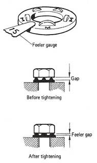
Figure 45
(Figure 44)
These washers should be placed under the nut or head of any bolt bearing on any bevelled surface. The angle of taper on the washer should match the angle of taper on the section. Washers are invariably marked with the angle of taper, i.e. 3°, 5° or 8°, or with the type of corner on H.S.F.G. taper washers (types B, C, D in Figure 44).
(Figure 45)
The "Coronet" Load Indicator is a specially hardened washer with protrusions on one face. The protrusions bear against the underside of the bolt head leaving a gap. As the bolt is tightened the protrusions are flattened and the gap reduced. At a specified average gap, measured by feeler gauge, the induced shank tension will not be less than the minimum required by Standards.
(Figure 46)
Where vibration is likely to be present to any degree in a fabrication, the nuts should be used with some form of spring washer to prevent the nut unscrewing during service.
Figure 46
(Figure 46, Figure 47)
Ordinary flat, low carbon steel washers are just punched into shape without further work but washers for turned barrel bolts are machined and should have a hole diameter not less than 1.6 mm larger than the barrel thickness and a thickness of not less than 3.2 mm so that the nut will not bear on the shoulder of the bolt. Flat washers for H.S.F.G. bolts are made from low alloy steel and are extremely hard and may be distinguished by the three tabs on the outer edge (Figure 47).
Figure 47
The legal requirement of the new Health and Safety at Work Act 1974 has created for both employers and employees a more acute awareness of the need to take care in avoiding accidents, injury and disease. The Act states: "It shall be the duty of EVERY employee while at work to take reasonable care for the health and safety of himself and of other persons who may be affected by his acts or omissions at work" (e.g. screening of the arc, wearing goggles, grinding and chipping away from others, replacing guards, keeping gangways clear, marking hot metal, etc.).
It is the duty of the employer to ensure that adequate protective equipment is available, and that adequate guarding of machines is maintained so that they are SAFE when PROPERLY USED (mechanical and photo-electric).
The employee (you) is required by law to wear certain protective devices in designated areas, for example eye protection. In addition to protective equipment such as helmets, goggles, spectacles, visors, ear muffs (noise), gloves, fireproof aprons and spats, toetector boots, etc. there are other factors to be considered to ensure your health and safety.
Figure 48 - Crane Signals
The following table shows the three main classes of fire and the approved fire extinguishing media.
Table 1 - Classes of Fire Risk
The following figures illustrate examples of the use of protective clothing and equipment.
Name
Main Use
Prevents burning of clothes.
Protects eyes from sparks.
Prevents skin burn.
Prevents crushing of toes.
No molten metal down boots.
Protects neck and chest
Name
Use
Protects tinted lens.
Limits glare.
Stops sparks.
Prevents misting up.
To change broken lens.
Adjust for size.
Name
D. (ii) Renewable tinted
Use
Takes away fumes.
Dust and fumes.
Prevents skin burn.
Takes spatter, etc.
Prevents arc eye.
For overhead work.
The filter mask (last figure, B) is no protection from dangerous gases such as phosgene (which is formed from degreasing agents such as trichloroethylene) or nitrous fumes (caused when large areas of plate are heated) or any other poisonous gases.
Source: http://local.ecollege.ie/Content/APPRENTICE/liu/metalfab_notes/module4/Splice%20Joints_M4_U9.doc
Web site to visit: http://local.ecollege.ie/
Author of the text: indicated on the source document of the above text
If you are the author of the text above and you not agree to share your knowledge for teaching, research, scholarship (for fair use as indicated in the United States copyrigh low) please send us an e-mail and we will remove your text quickly. Fair use is a limitation and exception to the exclusive right granted by copyright law to the author of a creative work. In United States copyright law, fair use is a doctrine that permits limited use of copyrighted material without acquiring permission from the rights holders. Examples of fair use include commentary, search engines, criticism, news reporting, research, teaching, library archiving and scholarship. It provides for the legal, unlicensed citation or incorporation of copyrighted material in another author's work under a four-factor balancing test. (source: http://en.wikipedia.org/wiki/Fair_use)
The information of medicine and health contained in the site are of a general nature and purpose which is purely informative and for this reason may not replace in any case, the council of a doctor or a qualified entity legally to the profession.
The texts are the property of their respective authors and we thank them for giving us the opportunity to share for free to students, teachers and users of the Web their texts will used only for illustrative educational and scientific purposes only.
All the information in our site are given for nonprofit educational purposes