
Terms
Actual Local Size (Da, da) : is the value of any individual distance at any cross section of a size feature as shown in Fig. 4-1. The actual local size is a two-point measurement, taken with an instrument like a caliper or micrometer, which is checked at a point along the cross section of the part. A feature of size may have several different values of actual local size.

Figure 4-1 Actual Local Size
Actual Mating Envelope (dfe): is defined according to the type of size feature being considered. The actual mating envelope of shaft is similar perfect feature counterpart of the smallest size that can be circumscribed about the feature so it just contacts the surfaces at the highest points. For example, a similar perfect counterpart could be a smallest cylinder of perfect form or two parallel planes of perfect form at a minimum separation. It just contacts the highest points of the surfaces. Actual mating envelope is a variable value and is derived from an actual part. See Fig.4-2 for examples. The actual mating envelope of a shaft dfe can be calculated as
![]() (4-1)
(4-1)
where da is the actual local size of a shaft and f is its form or position tolerance.
Figure 4-2 Actual Mating Envelope of a Shaft
The actual mating envelope of a hole (Dfe) is a similar perfect feature counterpart of the largest size that can be inscribed within the feature so that it just contacts the surfaces at their highest points. A similar perfect feature counterpart could be a largest cylinder of perfect form. It could also be two parallel planes of perfect form at the maximum separation that just contact the highest points of the surfaces. Actual mating envelope is a variable value and derived from an actual part. See Fig.4-3 for examples. The actual mating envelope of a hole Dfe can be calculated as
![]() (4-2)
(4-2)
where Da is the actual local size of a hole and f is its form or position tolerance.
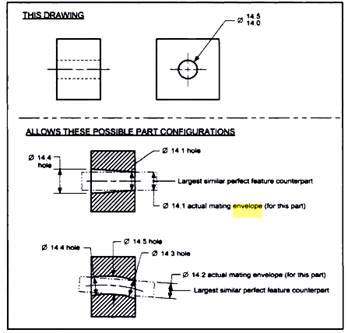
Figure 4-3 Actual Mating Envelope of a Hole
Virtual Condition (VC): is the theoretical extreme boundary of a size feature generated by the collective effects of MMC (the maximum material principle) and any applicable geometric tolerances. It is a worst-case boundary generated by the collective effects of a size feature at MMC or at LMC (the minimum material principle) and the geometric tolerance for that material condition. The VC of a size feature includes effects of the size, orientation, and location for the size feature. The virtual condition boundary is related to the datums that are referenced in the position tolerance used to determine the VC. Some examples of VC are shown in Fig.4-4.
Figure 4-4 Examples of Virtual Condition
Worst-Case Boundary (WCB): is a general term to refer to the extreme boundary of a size feature that is the worst-case for assembly. Depending upon the part dimensioning, a worst-case boundary can be a virtual condition, inner boundary, or outer boundary.
Inner Boundary (IB): is a worst-case boundary generated by the smallest size feature minus the stated form or position tolerance. Examples are given in Fig. 4-5.
Outer Boundary (OB): is a worst-case boundary generated by the largest feature size plus the stated form or position tolerance. Examples are given in Fig. 4-5.
When a form or position tolerance that contains no modifiers in the tolerance portion of the feature control frame is applied to a size feature, the inner or outer boundary of size feature is affected. On an external size feature, the term "outer boundary" or "worst-case boundary" is used. Outer boundary (OB) for an external size feature is the worst case boundary generated by the largest feature (MMC) plus the form or position tolerance. On an internal size feature, the term "inner boundary" is used. Inner boundary (IB) for an internal size feature is the smallest feature (MMC) minus the form or position tolerance.
In the case of an external size feature, such as a pin or a shaft, the OB is determined by the following formula:
OB=MMC + Form or Position Tolerance, i.e., ![]() (4-3)
(4-3)
In the case of an internal size feature, such as a hole, the IB is determined by the following formula:
IB=MMC - Form or Position Tolerance, i.e., ![]() (4-4)
(4-4)
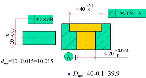
Figure4-5 Inner and Outer Boundary Examples
4.2 Tolerance Rules
In all cases, tolerances apply to features which are geometrical elements of a part, such as: lines, planes, circles, cylinders, cones, spheres, helixes, tore, and mathematically defined curves and surfaces (profiles). The main characteristics of a feature and a geometry are its size, form, orientation, and location. Size tolerances are referred to as dimensional tolerances, while form, profile, orientation, location and run-out tolerances are referred to as form or position tolerances.
Several principles and good practices for specifying tolerances are either explicitly defined or implied in the manufacturing tolerance standards. The principles help to ensure that: the functional, manufacturing and inspection intents are clear, the individual specifications form a consistent set of specifications with clear intent and priority, the specifications are realistic in the sense that they are producible and measurable, and unnecessary accumulation is minimized.
So, during the process of defining the tolerances of single parts or groups of components, according to ISO 8015, it must always be decided if the independence principle can allow for a toleranced size or if the envelope requirement has to be used. Additionally it must also be decided if a deviation of form or orientation, location or run-out has to be stated independently or if the maximum material requirement, minimum material requirement or reciprocity requirement can be allowed for certain form and position tolerances. Beside the previously discussed principles of tolerancing, other conditions like the projected tolerance according to ISO 1101 or the free state according to ISO 10579 are used in technical drawings (Fig.4-6). In this section, only principle of independency, envelope requirements, and maximum material principle would be introduced.
Principle of Tolerance Rules (ISO 1101)
4.2.1 Principle of Independency
Each specified dimensional or geometrical requirement on a drawing shall be met independently of other requirements, unless a particular relationship is specified. This is the fundamental principle of tolerancing and it is named the “principle of independency”. Therefore, where no relationship is specified, the form or position tolerance applies regardless of feature size and the two requirements are treated as being unrelated. Consequently, if a particular relationship of size and form (see the envelope requirement), or size and location, or size and orientation is required, it shall be specified on the drawing. When reference to the principle of independency is made on the drawing, the dimensional tolerance, regardless of whether it is expressed as a numerical tolerance or an ISO tolerance, does not control the form if the form deviation is such that it will not be detected by two-point measurement.
Form deviations are controlled through form and position tolerances. Form and position tolerances are used to control form, orientation and/or position on real or abstract features, regardless of the feature size. The form and position tolerances will, therefore, apply independently of the actual local sizes of individual features. The form and position deviations may be at a maximum whether or not the cross sections of the respective features are at the maximum material size. For instance, a shaft with the maximum material size at any cross-section may have a lobed form deviation within the circularity tolerance, and may also be bent by the amount of the straightness tolerance, see Figs 4-7a and 4-7b.
Figure 4-7 Principle of Independency: a) Drawing Indication; b) Interpretation
The linear and form and position tolerances are independent of each other, which mean that the form and position tolerances apply regardless of the feature size. The form and position deviations may be at maximum whether or not the cross-sections of the respective features are at the maximum material limit/size (the size of the smallest permissible hole or the size of the largest permissible shaft respectively). This is true unless a particular relationship has been specified.
For the component using principle of independency, its worst-case boundary is the boundary of limit sizes, i.e., the limits of sizes. Its qualified condition can be described as
![]() (4-5)
(4-5)
where f is the form or position error and t is the form or position tolerance.
Example1:
A part is shown in Fig.4-8. 1) Indicate the type of tolerance rule and boundary name; 2) calculate the boundary size and the value of the maximum straightness error; 3) if the actual size Da = ![]() 20.01 and form tolerance f =
20.01 and form tolerance f = ![]() 0.01, is the part qualified?
0.01, is the part qualified?
Solution:
Type of tolerance principle: principle of independency
Virtual condition: boundary of limit sizes, i.e., 20-20.033
![]()
![]()
The part is qualified.


Figure 4-8 A Part
4.2.2 Envelope Requirement
The envelope requirement is states that the real feature must not exceed the geometrical ideal envelope with the maximum material limit within the mating zone. The real size has to be as far away from the maximum material limit, as the expected deviation of form will be. In practice, the application of the envelope requirement means that if the actual size of the feature deviates from the maximum material limit, the form deviations are allowed to be larger.
The envelope requirement may be applied to a single feature, for instance, a cylindrical surface or a feature established by two parallel flat surfaces. The envelope requirement is used for features which are to be mated. The envelope requirement may be indicated either by the symbol![]() placed after the linear tolerance (Fig. 4-9a) or in relevant cases by reference to an appropriate standard which invokes the envelope requirement.
placed after the linear tolerance (Fig. 4-9a) or in relevant cases by reference to an appropriate standard which invokes the envelope requirement.
Fig.4-9a shows an example of the envelope requirement applied to a cylindrical feature. The function requirements are:
The drawing indication means that the actual part shall meet the following requirements:
Hence it follows that the shaft shall be exactly cylindrical when all actual local diameters are at the maximum material size of Ø150, see Fig.4-9e. On the drawings where the principle of independency is not applied, it is applied the envelope requirement for all the dimensional and form and position tolerance (the envelope requirement is not indicated). In this case, the tolerances are interpreted in the following ways within the prescribed length:
Figure 4-9 Envelope Requirement: a) Drawing Indication; b, c, d, e) Interpretation
The above interpretation means that if the part is everywhere at its maximum material limit, then the part should be perfectly round and straight, i.e. a perfect cylinder. Unless otherwise specified and subject to the above requirements deviation from a perfect cylinder may reach the full value of the diametrical tolerance specified.
In special cases, the maximum form deviations permitted by the above interpretation may be too large to allow satisfactory functioning of the assembled parts. In such cases, separate tolerances shall be given for the form, e.g. separate tolerances on circularity and/or straightness (see Fig.4-10). If we are adding on the previous example a complementary form exigency-circularity tolerance (Fig.4-10a), which is a compulsory restriction in comparison with the dimensional tolerance, the interpretation in given in the Fig.4-10b.
Figure4-10 Envelope Requirement: a) Drawing Indication; b) Interpretation
For the component using the envelope requirement, its worst-case boundary is the maximum material condition, i.e., the maximum material size DM, dM. Its qualified condition can be described as
 (4-6)
(4-6)
where Dfe and dfe are the actual mating envelope for hole and shaft, respectively.
Limitation of Envelope Requirements
A part often contains multiple features of size. Envelope rule does not affect the location, orientation, or relationship between features of size. Features of size shown perpendicular, symmetrical, or coaxial must be controlled for location or orientation to avoid incomplete drawing specifications. Often, implied 90 angles are covered by a general angular tolerance note or by an angular tolerance in the drawing title block.
Example2:
A shaft is shown in Fig.4-10. 1) Indicate the type of tolerance rule and boundary name; 2) calculate the boundary size and the value of the maximum straightness error; 3) if the actual size da= Φ19.98, form tolerance f =0.015, is the part qualified?
1) envelop requirement, maximum material boundary
2) dM=20mm,
f=|dM -dL|=20-19.979 =0.021
![]() 3)
3)
![]()
Part is qualified.

Figure4-10 A Shaft
4.2.3 Maximum Material Principle
The limit of size, together with geometrical form or position of a feature, is factors of the maximum material principle, and its application is restricted to those features whose size is specified by toleranced dimensions incorporating an axis or median plane. It can never be applied to a plane, surface, or line on a surface. The characteristics to which it can be applied are as follows: straightness, parallelism, squareness, angularity, position, concentricity, and symmetry. The characteristics to which the maximum material condition concept cannot be applied are flatness, roundness, cylindricity, profile of a line, profile of a surface, and run-out.
Fig.4-11(a) shows a typical drawing instruction where limits of size are applied to a pin, and in addition a straightness tolerance of 0.2 is applicable at the maximum material condition. Fig.4-11(b) shows the condition where the pin is finished at the maximum material condition with the maximum straightness error. The effective assembly diameter will be equal to the sum of the upper limit of size and the straightness tolerance. The straightness error is contained within a cylindrical tolerance zone of 0.2. To provide the same assembly diameter of 20.7 as shown in Fig.4-11(c) when the pin is finished at its low limit of size of 20.0, it follows that a straightness error of 0.7 could be acceptable. This increase may in some cases have no serious effect on the function of the component, and can be permitted.
(a) (b)
(c)
Figure4-11 Maximum Material Condition Applied to Straightness
For the component using the maximum material principle, its worst-case boundary is the inner boundary or the outer boundary, i.e., DMV, dMV. Its qualified condition can be described as
 (4-7)
(4-7)
where Dfe and dfe are the actual mating envelope for hole and shaft, respectively. DMV and dMV are the size of inner boundary and the size of outer boundary, respectively.
Figure4-12 A part
Source: http://ime.djtu.edu.cn/upload/pictures201011/101118131215bb17faa332595b31.doc
Web site to visit: http://ime.djtu.edu.cn
Author of the text: indicated on the source document of the above text
If you are the author of the text above and you not agree to share your knowledge for teaching, research, scholarship (for fair use as indicated in the United States copyrigh low) please send us an e-mail and we will remove your text quickly. Fair use is a limitation and exception to the exclusive right granted by copyright law to the author of a creative work. In United States copyright law, fair use is a doctrine that permits limited use of copyrighted material without acquiring permission from the rights holders. Examples of fair use include commentary, search engines, criticism, news reporting, research, teaching, library archiving and scholarship. It provides for the legal, unlicensed citation or incorporation of copyrighted material in another author's work under a four-factor balancing test. (source: http://en.wikipedia.org/wiki/Fair_use)
The information of medicine and health contained in the site are of a general nature and purpose which is purely informative and for this reason may not replace in any case, the council of a doctor or a qualified entity legally to the profession.
The texts are the property of their respective authors and we thank them for giving us the opportunity to share for free to students, teachers and users of the Web their texts will used only for illustrative educational and scientific purposes only.
All the information in our site are given for nonprofit educational purposes