Basically transducer is defined as a device, which converts energy or information from one form to another. These are widely used in measurement work because not all quantities that need to be measured can be displayed as easily as others. A better measurement of a quantity can usually be made if it may be converted to another form, which is more conveniently or accurately displayed. For example, the common mercury thermometerconverts variations in temperature into variations in the length of a column of mercury. Since the variation in the length of the mercury column is rather simple to measure, the mercury thermometer becomes a convenient device for measuring temperature. On the other hand, the actual temperature variation is not as easy to display directly. Another example is manometer, which detects pressure and indicates it directly on a scale calibrated in actual units of pressure.
Thus the transducer is a device, which provides a usable output in response to specific input measurand, which may be physical or mechanical quantity, property or condition. The transducer may be mechanical, electrical, magnetic, optical, chemical, acoustic, thermal nuclear, or a combination of any two or more of these.
Are simple and rugged in construction, cheaper in cost, accurate and operate without external power supplies but are not advantageous for many of the modern scientific experiments and process control instrumentation owing to their poor frequency response, requirement of large forces to overcome mechanical friction, in compatibility when remote control or indication is required, and a lot of other limitations. All these drawbacks have been overcome with the introduction of electrical transducers.
Mostly quantities to be measured are non-electrical such as temperature, pressure, displacement, humidity, fluid flow, speed etc., but these quantities cannot be measured directly. Hence such quantities are required to be sensed and changed into some other form for easy measurement.
Electrical quantities such as current, voltage, resistance inductance and capacitance etc. can be conveniently measured, transferred and stored, and therefore, for measurement of non-electrical quantities these are to be converted into electrical quantities first and then measured. The function of converting non-electrical quantity into electrical one is accomplished by a device called the electrical transducer. Basically an electrical transducer is a sensing device by which a physical, mechanical or optical quantity to be measured is transformed directly, with a suitable mechanism, into an electrical signal (current, voltage or frequency). The production of these signals is based upon electrical effects which may be resistive, inductive, capacitive etc in nature. The input versus output energy relationship takes a definite reproducible function. The output to input and the output to time behavior is predictable to a known degree of accuracy, sensitivity and response, within the specified environmental conditions.
The main function of a transducer is to respond only for the measurement under specified limits for which it is designed. It is, therefore, necessary to know the relationship between the input and output quantities and it should be fixed. Transducers should meet the following basic requirements.
1.4 Selection of Transducers:
In a measurement system the transducer (or a combination of transducers) is the input element with the critical function of transforming some physical quantity to a proportional electrical signal. So selection of an appropriate transducer is most important for having accurate results.
The first step in the selection procedure is to clearly define the nature of quantity under measurement (measurand) and know the range of magnitudes and frequencies that the measurand is expected to exhibit. Next step will be to examine the available transducer principles for measurement of desired quantity.
The type of transducer selected must be compatible with the type and range of the quantity to be measured and the output device.
In case one or more transducer principles are capable of generating a satisfactory signal, decision is to be taken whether to employ a commercially available transducer or build a suitable transducer. If the transducers are available in the market at a suitable price, the choice will probably be to purchase one of them, otherwise own transducer will have to be designed, built and calibrated.
The points to be considered in determining a transducer suitable for a specific measurement are as follows:
Such parameters are temperature, acceleration, shock and vibration, moisture, and corrosive chemicals might damage some transducers but not others.
However the total measurement error in a transducer-activated system may be reduced to fall within the required accuracy range by adopting the following techniques.
Controlling the measurement environment artificially in order to reduce possible transducer errors artificial environmental control includes the enclosing of the transducer in a temperature-controlled housing and isolating the device from external shocks and vibrations.
The transducers may be classified in various ways such as on the basis of electrical principles involved, methods of application, methods of energy conversion used, nature of output signal etc as shown in
table (1.1).
For example a thermistor used for the measurement of temperature fall in this category the thermistor senses the temperature directly and causes the change in resistance with the change in temperature.
When the input signal is sensed first by some detector or sensor and then its output being of some form other than input signals is given as input to a transducer for conversion into electrical form, then such a transducer falls in the category of secondary transducers.
For example, in case of pressure measurement, bourdon tube is a primary sensor which converts pressure first into displacement, and then the displacement is converted into an output voltage by an LVDT. In this case LVDT is secondary transducer.
Transducers, in which electrical parameters i.e. resistance, inductance or capacitance changes with the change in input signal, are called the passive transducers. These transducers require external power source for energy conversion. In such transducer electrical parameters i.e.resistance, inductance or capacitance causes a change in voltages current or frequency of the external power source. These transducers may draw sour energy from the system under measurement. Resistive, inductive and capacitive transducer falls in this category.
Sometimes an analog transducer combined with an ADC (analog-digital convector) is called a digital transducer.
Table (1-1)
Classification of Electrical Transducers
Class |
Electrical Parameters |
Types of Transducers |
Principle of Operation |
Typical Applications |
Passive Transducers |
Resistance |
Potentiometer |
Variation of resistance in a potentiometer or a bridge circuit due to positioning of a slide contact by an external force. |
Pressure, displace ment, position |
Resistance strain gauge |
Variation of resistance of a wire or a semi-conductor b y elongation or compression due to externally applied stress. |
Force, torque, displacement. |
||
Pirani gauge or hot- wire meter |
Variation of resistance of a heating element by convection cooling of a stream of gas. |
Gas flow, gas pressure. |
||
Resistance thermo- meter or pyrometer |
Variation of resistance of pure metal wire with the variation in temperature |
Temperature, radiant heat. |
||
Thermistor |
Variation of resistance of certain metal oxides having negative temperature coefficient of resistance with the variation in temperature. |
Temperature |
||
Resistance hygro- meter |
Variation of resistance of a conductive strip with moisture content. |
Relative humidity. |
||
Photoconductive cell |
Variation of resistance of a cell as a circuit element with incident light. |
Photosensitive relay. |
Class |
Electrical Parameters |
Types of Transducers |
Principle of Operation |
Typical Applications |
Passive Transducers |
Inductance |
Magnetic circuit breaker |
Variation of self or mutual inductance of an ac- excited coil by changes in the magnetic circuit |
Pressure, displace ment |
Reluctance pick up |
Variation of reluctance of the magnetic circuit by changing the position of the iron core of a coil. |
Pressure, displace- ment, vibration position. |
||
Differential trans- former |
Variation of differential voltage of two secondary windings of a transformer by varying the position of the magnetic core by an externally applied force. |
Force, pressure, position, displacement |
||
Eddy current gauge |
Variation of coil inductance by the proximity of an eddy current plate |
Displacement, thick ness |
||
Magnetostriction gauge |
Variation of magnetic properties by pressure and stress. |
Force, pressure, sound. |
||
capacitance |
Variable capaci- tance pressure gauge |
Variation in capacitance due to variation of distance between two parallel plates by an externally applied force. |
Pressure, displace ment. |
|
Capacitor micro - phone |
Variation of capacitance between a fixed plate and a movable diaphragm due to sound pressure. |
Speech, music, noise. |
||
Dielectric gauge |
Variation in capacitance because of changes in dielectric. |
Liquid level, thickness. |
Class |
Electrical Parameters |
Types of Transducers |
Principle of Operation |
Typical Applications |
Passive Transducers |
Voltage and current |
Hall effect pickup |
Generation of a potential difference across a semiconductor(germanium) plate due to interaction of magnetic flux with an applied current. |
Magnetic flux, current. |
Ionization chamber |
Induced electron flow by gas ionization due to radioactive radiation. |
Particle counting. |
||
Photoemissive cell |
Electron emission due to incident radiation on photoemissive surface |
Light and radiations. |
||
Photomultiplier tube |
Secondary electron emission due to incident radiation on photosensitive cathode |
Light and radiation, photosensitive relays. |
||
Active Transducers |
Voltage and current |
Thermocouple and thermopile |
Development of an emf across the junction of two dissimilar metals or semi conductors when that junction is heated. |
Temperature, heat flow, radiation |
Moving-coil gene- rator |
Generation of an emf due to motion of a coil in a magnetic field. |
Velocity, vibration |
||
Piezoelectric pickup |
Generation of an emf on applying an external force to a certain crystalline material such as quartz. |
Sound, vibration, acceleration, pressure variations. |
||
Photovoltaic cell |
Generation of a voltage in a semi-conductor junction device when radiant energy stimulates the cell |
Light meter, solar cell |
Class |
Electrical Parameters |
Types of Transducers |
Principle of Operation |
Typical Applications |
Digital transducers |
Train of pulses |
Encoders |
Translation of the shaft angular position into a digital number. |
Angular position |
Even counting |
Conversion of angular and translational motions into train of pulses by using either electromagnetic, capacitive or photo-electric method. |
Motion. |
||
Frequency output |
Conversion of analog signals into frequency. For example inductive or capacitive transducers can be incorporated in the tuned resonant circuit of an LC oscillator. |
Displacement, force, pressure, vibration |
Source: http://www.aast.edu/pheed/staffadminview/pdf_retreive.php?url=66_15575_EC%20732_2014_1__1_2_Chapter%201.doc&stafftype=staffcourses
Web site to visit: http://www.aast.edu/
Author of the text: indicated on the source document of the above text
Chapter 4 : Transducers - Generation and Detection of Ultrasound
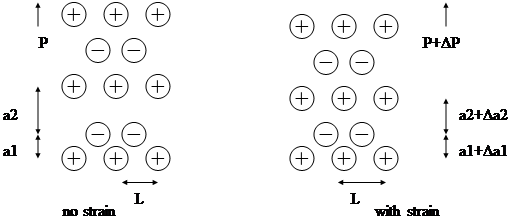
the polarization (per unit volume) of the object is
![]() .
.
![]() ,
,
where e is defined as the piezoelectric stress constant. The total change in electric displacement (or electric flux density) in the presence of an electric field E is
![]() ,
,
where e is the permittivity with zero or constant strain. We find that the electric displacement in a piezoelectric material is dependent on both the electric field and the strain.
 .
.
The average internal stress in the medium due to the electric field is
![]() .
.
The total stress (![]() ) applied to the object is the sum of the externally applied stress T (or
) applied to the object is the sum of the externally applied stress T (or ![]() ) and the internal stress TE (or
) and the internal stress TE (or ![]() ). According to Hooke’s law and defining
). According to Hooke’s law and defining ![]() as the elastic constant (under a constant electric field condition), we have
as the elastic constant (under a constant electric field condition), we have
![]()
![]()
(or ![]() ).
).
 .
.
Re-arranging the above equation, we obtain
![]()
![]() .
.
 .
.
 represents the propagation velocity in a non-piezoelectric medium. From the above equation, we have
 .
.
It is then obvious that acoustic waves propagate at a higher velocity when the material is being piezoelectrically stiffened. The elastic constant under a constant electric displacement condition (![]() ) is related to that under a constant electric field condition (
) is related to that under a constant electric field condition (![]() ) by
) by
 .
.
The quantity ![]() , where
, where ![]() , is known as the electromechanical coupling constant. The magnitude of the electromechanical coupling constant is a useful index of the strength of the piezoelectric effect in a particular material. Note that
, is known as the electromechanical coupling constant. The magnitude of the electromechanical coupling constant is a useful index of the strength of the piezoelectric effect in a particular material. Note that ![]() is the dielectric permittivity under a constant strain condition.
is the dielectric permittivity under a constant strain condition.

(a)
(b)
(c)
![]()
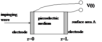
Using the constitutive relation relating the electric field to the strain and the electric displacement, the voltage becomes
![]()
From Gauss’s law, we have ![]() where
where ![]() is the total charge on area
is the total charge on area ![]() . Therefore, the above equation reduces to
. Therefore, the above equation reduces to
 .
.
where ![]() is the capacitance of the piezoelectric plate. The magnitude of the net displacement can be calculated from the boundary conditions placed at the surfaces of the material. In addition, the above equation shows that under open circuit situations, i.e.,
is the capacitance of the piezoelectric plate. The magnitude of the net displacement can be calculated from the boundary conditions placed at the surfaces of the material. In addition, the above equation shows that under open circuit situations, i.e., ![]() is not time-varying, the voltage developed across the plate is directly related to the relative displacements of the front and back surfaces of the material. If the thickness of the plate corresponds to an odd integral number of half-wavelengths of the ultrasonic wave impinging on the material (i.e., the two surfaces oscillate 180o out of phase), then the relative displacement of the front and back surfaces,
is not time-varying, the voltage developed across the plate is directly related to the relative displacements of the front and back surfaces of the material. If the thickness of the plate corresponds to an odd integral number of half-wavelengths of the ultrasonic wave impinging on the material (i.e., the two surfaces oscillate 180o out of phase), then the relative displacement of the front and back surfaces, ![]() , is the largest. In contrast, if the thickness of the crystal is an even number of half-wavelengths, then the amplitude of oscillation of the two surfaces is in phase, and therefore,
, is the largest. In contrast, if the thickness of the crystal is an even number of half-wavelengths, then the amplitude of oscillation of the two surfaces is in phase, and therefore, ![]() .
.
Taking the partial derivative with respect to time on both sides, we obtain
![]()
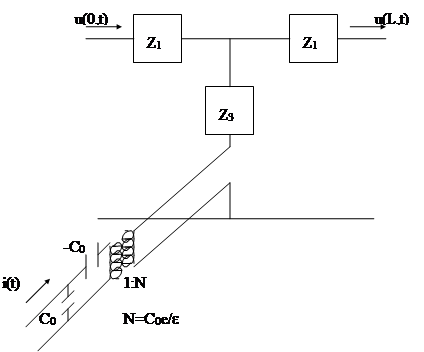
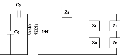
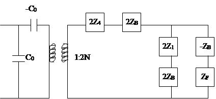
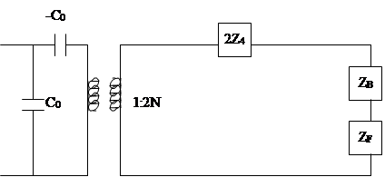
which can be represented by the following equivalent circuit.
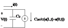
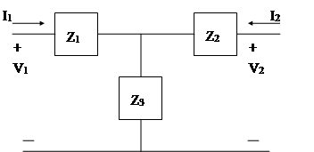
where ![]() due to symmetry. Let
due to symmetry. Let ![]() represent the characteristic impedance of the piezoelectric material, we can obtain the following equations using methods similar to those used by deriving the acoustic wave equations
represent the characteristic impedance of the piezoelectric material, we can obtain the following equations using methods similar to those used by deriving the acoustic wave equations
 .
.
 .
.
Letting ![]() , the following equation yields
, the following equation yields
![]() .
.
Therefore
![]() .
.
and

Furthermore, ![]() (=
(=![]() ) can be obtained as the following:
) can be obtained as the following:
![]()
- D. Leedom, R. Krimholtz and G. Matthael, “Equivalent circuits for transducers having even or odd symmetry piezoelectric excitation”, IEEE Trans. on Sonics and Ultrasonics, vol. SU-18, No. 3, pp. 128-141, July 1971.
![]()

By placing a lossy material (highly attenuating) which has a similar acoustic impedance as the PZT, the reflection at the back of the transducer can be reduced and therefore the pulse can be shortened. Apparently, sensitivity is degraded due to attenuation.
![]()
![]()
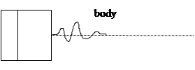
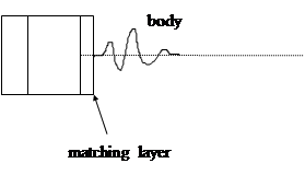
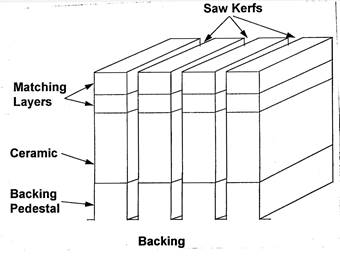
The acoustic impedance of a typical PZT material is around twenty times higher than that in the body, therefore, part of the sensitivity loss can be recovered by adding one or multiple quarter wave matching layers at the front surface of the transducer.
![]()
![]()
Source: http://home.ee.ntu.edu.tw/classnotes/us1/chapter4.doc
Web site to visit: http://home.ee.ntu.edu.tw
Author of the text: indicated on the source document of the above text
Basically transducer is defined as a device, which converts energy or information from one form to another. These are widely used in measurement work because not all quantities that need to be measured can be displayed as easily as others. A better measurement of a quantity can usually be made if it may be converted to another form, which is more conveniently or accurately displayed. For example, the common mercury thermometerconverts variations in temperature into variations in the length of a column of mercury. Since the variation in the length of the mercury column is rather simple to measure, the mercury thermometer becomes a convenient device for measuring temperature. On the other hand, the actual temperature variation is not as easy to display directly. Another example is manometer, which detects pressure and indicates it directly on a scale calibrated in actual units of pressure.
Thus the transducer is a device, which provides a usable output in response to specific input measurand, which may be physical or mechanical quantity, property or condition. The transducer may be mechanical, electrical, magnetic, optical, chemical, acoustic, thermal nuclear, or a combination of any two or more of these.
Are simple and rugged in construction, cheaper in cost, accurate and operate without external power supplies but are not advantageous for many of the modern scientific experiments and process control instrumentation owing to their poor frequency response, requirement of large forces to overcome mechanical friction, in compatibility when remote control or indication is required, and a lot of other limitations. All these drawbacks have been overcome with the introduction of electrical transducers.
Mostly quantities to be measured are non-electrical such as temperature, pressure, displacement, humidity, fluid flow, speed etc., but these quantities cannot be measured directly. Hence such quantities are required to be sensed and changed into some other form for easy measurement.
Electrical quantities such as current, voltage, resistance inductance and capacitance etc. can be conveniently measured, transferred and stored, and therefore, for measurement of non-electrical quantities these are to be converted into electrical quantities first and then measured. The function of converting non-electrical quantity into electrical one is accomplished by a device called the electrical transducer. Basically an electrical transducer is a sensing device by which a physical, mechanical or optical quantity to be measured is transformed directly, with a suitable mechanism, into an electrical signal (current, voltage or frequency). The production of these signals is based upon electrical effects which may be resistive, inductive, capacitive etc in nature. The input versus output energy relationship takes a definite reproducible function. The output to input and the output to time behavior is predictable to a known degree of accuracy, sensitivity and response, within the specified environmental conditions.
The main function of a transducer is to respond only for the measurement under specified limits for which it is designed. It is, therefore, necessary to know the relationship between the input and output quantities and it should be fixed. Transducers should meet the following basic requirements.
1.4 Selection of Transducers:
In a measurement system the transducer (or a combination of transducers) is the input element with the critical function of transforming some physical quantity to a proportional electrical signal. So selection of an appropriate transducer is most important for having accurate results.
The first step in the selection procedure is to clearly define the nature of quantity under measurement (measurand) and know the range of magnitudes and frequencies that the measurand is expected to exhibit. Next step will be to examine the available transducer principles for measurement of desired quantity.
The type of transducer selected must be compatible with the type and range of the quantity to be measured and the output device.
In case one or more transducer principles are capable of generating a satisfactory signal, decision is to be taken whether to employ a commercially available transducer or build a suitable transducer. If the transducers are available in the market at a suitable price, the choice will probably be to purchase one of them, otherwise own transducer will have to be designed, built and calibrated.
The points to be considered in determining a transducer suitable for a specific measurement are as follows:
Such parameters are temperature, acceleration, shock and vibration, moisture, and corrosive chemicals might damage some transducers but not others.
However the total measurement error in a transducer-activated system may be reduced to fall within the required accuracy range by adopting the following techniques.
Controlling the measurement environment artificially in order to reduce possible transducer errors artificial environmental control includes the enclosing of the transducer in a temperature-controlled housing and isolating the device from external shocks and vibrations.
The transducers may be classified in various ways such as on the basis of electrical principles involved, methods of application, methods of energy conversion used, nature of output signal etc as shown in
table (1.1).
For example a thermistor used for the measurement of temperature fall in this category the thermistor senses the temperature directly and causes the change in resistance with the change in temperature.
When the input signal is sensed first by some detector or sensor and then its output being of some form other than input signals is given as input to a transducer for conversion into electrical form, then such a transducer falls in the category of secondary transducers.
For example, in case of pressure measurement, bourdon tube is a primary sensor which converts pressure first into displacement, and then the displacement is converted into an output voltage by an LVDT. In this case LVDT is secondary transducer.
Transducers, in which electrical parameters i.e. resistance, inductance or capacitance changes with the change in input signal, are called the passive transducers. These transducers require external power source for energy conversion. In such transducer electrical parameters i.e.resistance, inductance or capacitance causes a change in voltages current or frequency of the external power source. These transducers may draw sour energy from the system under measurement. Resistive, inductive and capacitive transducer falls in this category.
Sometimes an analog transducer combined with an ADC (analog-digital convector) is called a digital transducer.
Table (1-1)
Classification of Electrical Transducers
Class |
Electrical Parameters |
Types of Transducers |
Principle of Operation |
Typical Applications |
Passive Transducers |
Resistance |
Potentiometer |
Variation of resistance in a potentiometer or a bridge circuit due to positioning of a slide contact by an external force. |
Pressure, displace ment, position |
Resistance strain gauge |
Variation of resistance of a wire or a semi-conductor b y elongation or compression due to externally applied stress. |
Force, torque, displacement. |
||
Pirani gauge or hot- wire meter |
Variation of resistance of a heating element by convection cooling of a stream of gas. |
Gas flow, gas pressure. |
||
Resistance thermo- meter or pyrometer |
Variation of resistance of pure metal wire with the variation in temperature |
Temperature, radiant heat. |
||
Thermistor |
Variation of resistance of certain metal oxides having negative temperature coefficient of resistance with the variation in temperature. |
Temperature |
||
Resistance hygro- meter |
Variation of resistance of a conductive strip with moisture content. |
Relative humidity. |
||
Photoconductive cell |
Variation of resistance of a cell as a circuit element with incident light. |
Photosensitive relay. |
Class |
Electrical Parameters |
Types of Transducers |
Principle of Operation |
Typical Applications |
Passive Transducers |
Inductance |
Magnetic circuit breaker |
Variation of self or mutual inductance of an ac- excited coil by changes in the magnetic circuit |
Pressure, displace ment |
Reluctance pick up |
Variation of reluctance of the magnetic circuit by changing the position of the iron core of a coil. |
Pressure, displace- ment, vibration position. |
||
Differential trans- former |
Variation of differential voltage of two secondary windings of a transformer by varying the position of the magnetic core by an externally applied force. |
Force, pressure, position, displacement |
||
Eddy current gauge |
Variation of coil inductance by the proximity of an eddy current plate |
Displacement, thick ness |
||
Magnetostriction gauge |
Variation of magnetic properties by pressure and stress. |
Force, pressure, sound. |
||
capacitance |
Variable capaci- tance pressure gauge |
Variation in capacitance due to variation of distance between two parallel plates by an externally applied force. |
Pressure, displace ment. |
|
Capacitor micro - phone |
Variation of capacitance between a fixed plate and a movable diaphragm due to sound pressure. |
Speech, music, noise. |
||
Dielectric gauge |
Variation in capacitance because of changes in dielectric. |
Liquid level, thickness. |
Class |
Electrical Parameters |
Types of Transducers |
Principle of Operation |
Typical Applications |
Passive Transducers |
Voltage and current |
Hall effect pickup |
Generation of a potential difference across a semiconductor(germanium) plate due to interaction of magnetic flux with an applied current. |
Magnetic flux, current. |
Ionization chamber |
Induced electron flow by gas ionization due to radioactive radiation. |
Particle counting. |
||
Photoemissive cell |
Electron emission due to incident radiation on photoemissive surface |
Light and radiations. |
||
Photomultiplier tube |
Secondary electron emission due to incident radiation on photosensitive cathode |
Light and radiation, photosensitive relays. |
||
Active Transducers |
Voltage and current |
Thermocouple and thermopile |
Development of an emf across the junction of two dissimilar metals or semi conductors when that junction is heated. |
Temperature, heat flow, radiation |
Moving-coil gene- rator |
Generation of an emf due to motion of a coil in a magnetic field. |
Velocity, vibration |
||
Piezoelectric pickup |
Generation of an emf on applying an external force to a certain crystalline material such as quartz. |
Sound, vibration, acceleration, pressure variations. |
||
Photovoltaic cell |
Generation of a voltage in a semi-conductor junction device when radiant energy stimulates the cell |
Light meter, solar cell |
Class |
Electrical Parameters |
Types of Transducers |
Principle of Operation |
Typical Applications |
Digital transducers |
Train of pulses |
Encoders |
Translation of the shaft angular position into a digital number. |
Angular position |
Even counting |
Conversion of angular and translational motions into train of pulses by using either electromagnetic, capacitive or photo-electric method. |
Motion. |
||
Frequency output |
Conversion of analog signals into frequency. For example inductive or capacitive transducers can be incorporated in the tuned resonant circuit of an LC oscillator. |
Displacement, force, pressure, vibration |
Source: http://www.aast.edu/pheed/staffadminview/pdf_retreive.php?url=66_15575_EC%20732_2014_1__1_2_Chapter%201.doc&stafftype=staffcourses
Web site to visit: http://www.aast.edu/
Author of the text: indicated on the source document of the above text
If you are the author of the text above and you not agree to share your knowledge for teaching, research, scholarship (for fair use as indicated in the United States copyrigh low) please send us an e-mail and we will remove your text quickly. Fair use is a limitation and exception to the exclusive right granted by copyright law to the author of a creative work. In United States copyright law, fair use is a doctrine that permits limited use of copyrighted material without acquiring permission from the rights holders. Examples of fair use include commentary, search engines, criticism, news reporting, research, teaching, library archiving and scholarship. It provides for the legal, unlicensed citation or incorporation of copyrighted material in another author's work under a four-factor balancing test. (source: http://en.wikipedia.org/wiki/Fair_use)
The information of medicine and health contained in the site are of a general nature and purpose which is purely informative and for this reason may not replace in any case, the council of a doctor or a qualified entity legally to the profession.
The texts are the property of their respective authors and we thank them for giving us the opportunity to share for free to students, teachers and users of the Web their texts will used only for illustrative educational and scientific purposes only.
All the information in our site are given for nonprofit educational purposes