|
||||||||
|
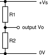
A voltage divider consists of two resistances R1 and R2 connected in series across a supply voltage Vs. The supply voltage is divided up between the two resistances to give an output voltage Vo which is the voltage across R2. This depends on the size of R2 relative to R1:
If you need a precise value for the output voltage Vo you can use Ohm's law and a little algebra to work out the formula for Vo shown on the right. The formula and the approximate rules given above assume that negligible current flows from the output. This is true if Vo is connected to a device with a high resistance such as voltmeter or a chip input. For further information please see the page on impedance. If the output is connected to a transistor Vo cannot become much greater than 0.7V because the transistor's base-emitter junction behaves like a diode.
Voltage dividers are also called potential dividers, a name which comes from potential difference (the proper name for voltage).
One of the main uses of voltage dividers is to connect input transducers into circuits...
Most input transducers (sensors) vary their resistance and usually a voltage divider is used to convert this to a varying voltage which is more useful. The voltage signal can be fed to other parts of the circuit, such as the input to a chip or a transistor switch.
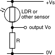
The sensor is one of the resistances in the voltage divider. It can be at the top (R1) or at the bottom (R2), the choice is determined by when you want a large value for the output voltage Vo:
Then you need to choose a value for the resistor...
|
OR |
|
The value of the resistor R will determine the range of the output voltage Vo. For best results you need a large 'swing' (range) for Vo and this is achieved if the resistor is much larger than the sensor's minimum resistance Rmin, but much smaller than the sensor's maximum resistance Rmax.
You can use a multimeter to help you find the minimum and maximum values of the sensor's resistance (Rmin and Rmax). There is no need to be precise, approximate values will do.
Then choose resistor value: R = square root of (Rmin × Rmax)
Choose a standard value which is close to this calculated value.
For example:
An LDR: Rmin = 100![]() , Rmax = 1M
, Rmax = 1M![]() , so R = square root of (100 × 1M) = 10k
, so R = square root of (100 × 1M) = 10k![]() .
.
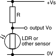
The resistor and sensor can be swopped over to invert the action of the voltage divider. For example an LDR has a high resistance when dark and a low resistance when brightly lit, so:
|
The sensor and variable |
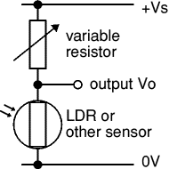
A variable resistor may be used in place of the fixed resistor R. It will enable you to adjust the output voltage Vo for a given resistance of the sensor. For example you can use a variable resistor to set the exact brightness level which makes a chip change state.
The variable resistor value should be larger than the fixed resistor value. For finer control you can use a fixed resistor in series with the variable resistor. For example if a 10k![]() fixed resistor is suitable you could replace it with a fixed 4.7k
fixed resistor is suitable you could replace it with a fixed 4.7k![]() resistor in series with a 10k
resistor in series with a 10k![]() variable resistor, allowing you to adjust the resistance from 4.7k to 14.7k
variable resistor, allowing you to adjust the resistance from 4.7k to 14.7k![]() .
.
If you are planning to use a variable resistor connected between the +Vs supply and the base of a transistor you must include a resistor in series with the variable resistor. This is to prevent excessive base current destroying the transistor when the variable resistor is reduced to zero. For further information please see the page on Transistor Circuits.
Source: http://folders.sirthomasboughey.staffs.sch.uk/easylink/intranet/stbh/files/staff1/Voltage%20Dividers.doc
Web site to visit: http://folders.sirthomasboughey.staffs.sch.uk
Author of the text: indicated on the source document of the above text
If you are the author of the text above and you not agree to share your knowledge for teaching, research, scholarship (for fair use as indicated in the United States copyrigh low) please send us an e-mail and we will remove your text quickly. Fair use is a limitation and exception to the exclusive right granted by copyright law to the author of a creative work. In United States copyright law, fair use is a doctrine that permits limited use of copyrighted material without acquiring permission from the rights holders. Examples of fair use include commentary, search engines, criticism, news reporting, research, teaching, library archiving and scholarship. It provides for the legal, unlicensed citation or incorporation of copyrighted material in another author's work under a four-factor balancing test. (source: http://en.wikipedia.org/wiki/Fair_use)
The information of medicine and health contained in the site are of a general nature and purpose which is purely informative and for this reason may not replace in any case, the council of a doctor or a qualified entity legally to the profession.
The texts are the property of their respective authors and we thank them for giving us the opportunity to share for free to students, teachers and users of the Web their texts will used only for illustrative educational and scientific purposes only.
All the information in our site are given for nonprofit educational purposes