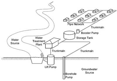
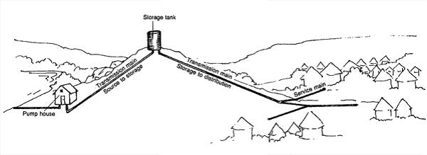
A distribution system generally includes the following main elements:
Figure 1: A water supply system
This booklet is part of the Resources for Drinking-water Assistance Programme. Further guidance is available on other aspects of planning, developing and operating small drinking-water supplies, including:
These resources are all available from the Ministry of Health at: www.govt.moh.nz.
Distribution systems serving small communities generally fall within one of the following categories: on-demand system, restricted-flow system or rural agricultural water supply.
The most common design is an on-demand system. Within practical limits, consumers connected to an on-demand system are able to take as much water as they wish, when they wish.
On-demand systems are often the most cost-effective means of supply when the distribution system also provides water for fire-fighting. This is because fire-fighting systems must deliver a very high flow of water. For the majority of the time water is not needed for fire-fighting, and the pipe capacity will be sufficient to supply water to the consumers, even at their highest consumption rate.
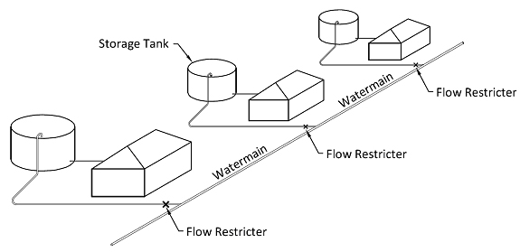
Restricted-flow systems are common in small communities. In this type of system a small continuous flow is supplied to each consumer through a control device fitted to the supply line. Each consumer has their own storage tank, and this allows them to draw off larger flows when they need to. Normally the tank is large enough to hold water for 24 hours of use.
Restricted-flow systems deliver water at a flow rate that is about one-fifth the peak flow in an on-demand system. This greatly reduces the cost of treatment, pumping and piping components. Restricted-flow systems also have the advantage that water is supplied to the tank by way of a ball-cock valve, which has an air separation gap. This greatly reduces the possibility of reverse flow of water back into the network (backflow). Further information on backflow contamination is given in section 10.
Figure 2: A restricted-flow system
The main purpose of a rural agricultural water supply is to provide water for stock and irrigation rather than household use. These systems often supply untreated or partially treated water. If the water is used by a household, the consumer is likely to need to treat it before using it. Treatment for systems of this type can be provided in the form of ‘point of use’ installations incorporating cartridge-type filters and small ultraviolet inactivation systems.
Rural water supplies can be particularly vulnerable to backflow contamination because they are often unchlorinated, and there is a risk of contamination from stock troughs and other similar hazards.
The water consumed by a community will fall under one or more of the following categories:
The amount of water used by a community is usually calculated based on the number of people that either live there or visit. The water used by each person living in a community generally ranges from about 180 litres per day for seasonal holiday communities up to around 250 litres per day for larger towns and cities. These figures allow for normal domestic use and a small amount of garden watering, but not for heavy water use such as irrigation, filling swimming pools or serious leakage. These can lead to much higher water consumption figures. Figures around 2000 litres per person per day are not unheard of in some communities.
One way to work out how much water will be required by a community is to use water meters to measure the usage over a set period in a local area similar to the one for which a pipe network is planned. The consumption can then be compared based on the number of people living in each community. Note, however, that measuring the actual water used by households with rain tanks can be deceptive, because consumption can increase significantly when there is no longer a danger of running out of water.
The non-household water consumed will depend on the nature of the activity and should be discussed with the water user. Such users may include farmers (for stock water), or small businesses such as hairdressers and butchers.
Water lost through leakage depends on the condition of the pipe network. When a network is well built and new the leakage rate will be small, but this will gradually increase over time. Leakage rates of around 20 percent of the total water supplied are common in older systems.
Water demand management is described in the booklet Managing Projects for Small Drinking-water Supplies.
Although it is useful to know how much water will be needed over the course of an average day, the pipes and storage would normally be designed to provide for the maximum amount that may be required. The peak demand can occur with normal use, such as in the mornings and evenings, in summer and in dry years. The peak demand may also occur in a local area when supplying water for fire-fighting. The pattern of water demand is described in section 5 of Treatment Options for Small Supplies.
Methods for estimating the peak day demand are given in New Zealand Standard NZS4404:2004 (currently under review). This standard for Land Development and Subdivision Engineering recommends the following peaking factors for populations below 2000:
Note that the instantaneous flows that occurs in pipe networks could be a lot higher than those calculated using the guideline figures shown above.
For very small communities it may be more appropriate to estimate the peak demand by evaluating the number of supply points (taps) at each house in the supply area and calculating an instantaneous flow by applying a flow rate to each.
Because pipe networks are normally designed to last for 80 to 100 years, distribution systems are frequently installed with spare capacity for future community growth. Some consideration should be given to the likelihood of community growth and the effect that installing larger pipes will have on costs. Often it costs very little more for a slightly larger pipe when the cost of installation is being considered.
However, bear in mind that installing excessively large pipes can mean the water travels very slowly through them. This means the chlorine in the water can become depleted. Design and management methods to control this issue are discussed later in the booklet.
The flow rate is often discussed in relation to water distribution systems. This is the volume of water that passes a point in a specific time interval. It is normally measured in litres per second, but other common units include litres per minute and cubic metres per hour.
The basic flow equation for the flow rate (Q) is:
Q = A x V
The ‘A’ stands for the cross-sectional area of the flowing stream of water. If the flow is in a pipe, the area is calculated from the inside diameter of the pipe using a formula for the area of a circle. The ‘V’ in the formula stands for the velocity of flow, or speed at which the water is moving. It is normally expressed in metres per second.
If the area is expressed in square metres and the velocity in metres per second, the resulting flow rate will be in cubic metres per second.
When water is stored in a tank, the weight of the water exerts pressure on the sides and base of the tank. The deeper the water, the greater the pressure at the bottom of the tank. When water is ‘static’ (not flowing), the amount of pressure depends only on the height of the water and not on the volume of the pipe or tank. For example, the pressure at the bottom of a 5 m high storage tank is the same as the pressure at the bottom of a 5 m high 50 mm pipe.
This principle is used to create pressure in a distribution network, such as by placing a storage tank at the top of a hill. The same effect can be created artificially using pumps to force water into a network under pressure.
Figure 3: Static head either side of a pump
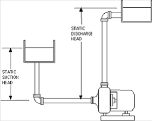
Pressure is often measured as ‘head’ of water. The ‘head’ is the height of water that would give the same pressure. For example, a pump may be able to deliver a maximum pressure equivalent to a 30 m head of water. An open tank located above the pump would fill to a height of 30 m.
There are many different units used for pressure. The most commonly used ones are metres of head of water, kilopascals (kPa) and pounds per square inch (psi).
Minimum and maximum service pressures in a network are typically set by local authority codes of practice.
When water is flowing along a horizontal pipe, the pressure in the pipe gradually reduces due to friction between the water and the pipe walls. Friction losses are normally expressed as ‘head loss per metre of pipe’. For example, a 100 mm pipe flowing at 6 L/s has a head loss of approximately 1 m per 100 m of pipe length. For a particular flow rate, the larger the pipe, the smaller the friction loss. This is why the pipes in a network generally branch out into smaller and smaller pipes as the flow rate in each pipe decreases.
Friction losses are often the reason why network pressure fluctuates with water demand. A high water demand leads to lower water pressure. Friction losses need to be allowed for, along with the static pressure, when calculating the pressure in a pipe at a particular location.
When something is moving, and that something is large and heavy, it is not easily stopped. This is true of moving water. The energy of the moving water has to be contained by a pipe system when the flow stops. The more quickly the flow rate changes, and the greater the volume of moving water in a pipe, the greater the effect of the change.
The release of this energy is often experienced as a loud bang when shutting a household tap. In larger systems this ‘water hammer’ effect can seriously damage pipes and fittings. There are specific designs and methods of operation that prevent this form of damage.
Where pipe velocities are likely to exceed 2 m/s, the design should be checked for the potential for water hammer, particularly in long sections of pipe. This would need to be undertaken by an appropriately trained person.
Most distribution systems need storage in order to be able to function effectively. Storage is particularly important where the supply water is treated before distribution to consumers, because it means the treatment plant does not need to be sized to treat the peak flow that consumers require. The storage reservoir provides a buffer between the treatment plant and the consumers.
Storage can also help to maintain pressure levels by evening out the flow in a network. The most extreme example of this is in restricted-flow systems where every customer has their own tank, which is topped up by a small constant flow from the distribution pipe network.
The storage can be used to provide chlorine contact time for the inactivation of micro-organisms and as a reserve of treated water in the event of a power cut or treatment plant malfunction.
The sections that follow describe the important features that need to be considered when designing a storage system.
The total amount of storage needs to be enough to even out peak flows, plus an allowance for plant failure or emergencies, and fire flows.
Peak demand/ efficiency |
The absolute minimum size of the treated water storage needed is based on the rate that water can be delivered to a location compared to the peak water demand. This delivery rate will typically be limited by the capacity of the source/treatment stage. The water level in the storage tank will fall during times of peak demand and has to be replaced during low water demand periods. |
Emergency storage |
The ability to store water can be one of the most important safety features in a water supply. When something has gone wrong, the stored water gives time to complete repairs. Issues that should be considered when deciding on the size of the water storage are:
|
Fire flows |
Additional storage is often needed to meet fire-fighting requirements. In small systems, the volume required can be significant compared to the size of the water supply. In very small systems it may be more practical to provide separate storage tanks for storing fire-supply water. This needs to be discussed with the local fire authorities. |
There are mathematical methods for calculating the required amount of storage to balance out peak flows. The idea behind these methods is to make sure the storage level will remain above the minimum needed for emergencies and fires at all times. Typically a water supply should have at least 24 hours’ water storage at the average demand. Ideally, 48 hours of water would be stored. The provision of too much storage can result in water in the tanks not being replaced or ‘turned over’ on a regular basis, which could have an effect on water quality.
For further information on water storage design seek professional advice.
The effect of gravity means that the higher a water storage tank is in relation to an outlet from the distribution system, the greater the water pressure at the outlet. This means a storage tank located at a high point in relation to the network will keep the water in the network under a reasonably constant pressure, without a need to boost the pressure with pumps.
An elevated storage tank is typically located high enough for all of the water pressure in the network to be provided by gravity.
Figure 5: Elevated storage tank, Hawera
Where there is no high ground, water towers can be used to give the desired elevation. Water towers are no longer common for larger water supplies in New Zealand because of the expense in meeting earthquake safety requirements and the visual impact of these structures. Pressure-sustaining pumps are now a more usual solution. However, for water supplies serving a small population, water towers may still be cost-effective.
For on-demand systems, the best location for a storage tank is often between the source or treatment and the service area, as shown in Figure 6. This location means that all of the water must travel through the tank, helping to maintain turnover. As long as the minimum level is maintained, the tank can also be used to provide chlorine contact time.
Figure 6: Storage tank location in between source and service area
For on-demand systems it is common to provide several tanks located throughout the distribution area. The advantages of using more than one storage tank are:
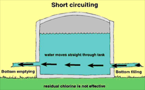
The residual chlorine level (or amount of chlorine available in the water to provide disinfection) of water leaving storage tanks can be greatly influenced by the amount of time the water spends in the tank. This ‘residence time’ is affected by the degree of mixing and short-circuiting in the tank.
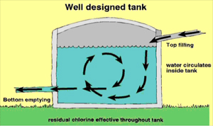
Ideally, water entering the storage tanks should mix with the water already in the storage tanks rather than taking a short cut through the tank, which can lead to variability in the chlorine residual leaving the tank. Wherever possible it is best to have separate pipes for filling and draining the tank, and to have these positioned in a way that encourages mixing. The effect of inlet and outlet position on mixing is shown in Figure 7.
Figure 7: The position of the inlet and outlet affects mixing in the tank
a) Short circuit situation |
b) Mixed flow situation |
|
|
Figure 8 shows a typical layout of pipes and valves associated with a storage tank. In addition to the inlet and outlet, there are drainage (sluice) outlets, air vents and overflow pipes.
A drain line allows the tank to be drained for cleaning and other maintenance. If the outlet for draining the tanks discharges to a sewer or storm water system, an air gap or other backflow prevention system must be provided to stop water being sucked back into the tank. A bypass is normally included to allow for taking the tank out of service for maintenance.
Storage tanks need some form of level control so that they don’t overflow when they are full. In some cases this may be a stopcock valve, similar to what is used in a toilet cistern. Another option is to use electrical level switches to open and shut valves or switch pumps on and off. An overflow pipe should always be provided in case the level control mechanism fails.
Storage tanks need to be easy to access for maintenance and operational purposes. Permanent vertical ladders are often installed on the outside of the tank for access to the roof, where the entry hatch is usually located. Any access system needs to be safe and easy, even under wet and windy conditions. There are a number of safety features that can help with this. These include guardrails, safety cages, harness attachment points, equipment hoists and easily removable access covers.
Access covers should be designed with a raised lip to prevent water running off the roof and into the tank. The roof should also have a slope angle of at least 2 percent to prevent the ponding of water.
Tanks need to be secure against vandalism and contamination. It is useful to have a security fence and locked hatches as protection against unauthorised access. Small animals, insects and birds need to be prevented from entering the storage tanks and contaminating the water. Openings such as the air vent should be covered with a corrosion-resistant screen that is fine enough to exclude insects. Ideally, vents should face downward to exclude rainwater. Overflow pipes can be covered by a screen or a flap valve.
Storage tanks are available in a wide range of materials. More durable tanks that are initially more expensive may be cheaper in the long term when maintenance and replacement costs are allowed for. Table 1 describes the advantages and disadvantages of the common tank materials.
Table 1: Storage tank materials
Storage tank type |
Advantages |
Limitations |
Polyethylene |
Often cost-effective for smaller tanks |
Will eventually be damaged by sunlight |
Timber staves with plastic liner |
Initial capital cost may be low |
Treated timber has potential to contaminate water if roof does not have a plastic liner |
Coated steel or steel with plastic liner |
Initial capital cost may be low |
Corrosion protection required |
Concrete |
Likely to be cost-effective for larger tanks |
Specialist design for large tanks and foundations |
For many small supplies a practical and cost-effective alternative to a large tank that has to be built on-site may be to use a number of smaller tanks that can be delivered by truck and installed without specialist expertise. For example, four 30 m3 polyethylene tanks could be used when a community wishes to install 120 m3 of storage. The four tanks would be constructed on a prepared platform and connected with valved inlet and outlet pipework.
It is also important to ensure that any materials used are suitable for contact with drinking-water. This applies particularly to paint systems and plastic liners. There are a number of appropriate certifications that prove the suitability of materials for potable water use.
For information on considerations when siting storage, please seek professional advice.
The design of the distribution pipe network primarily needs to allow for the delivery of adequate water to consumers. Clearly it is also important to minimise the risk that water will become contaminated and to avoid disruption to the supply if repairs are needed. The following sections introduce the terminology that is used to describe pipes in different parts of the network and the ways the system can be designed.
The following terms are used to describe the pipes in a distribution system.
Trunk main |
This takes water from the storage tank or source to the rest of the pipe network. Trunk mains are not normally used to supply consumers directly. |
Distribution main |
This is the general collective term for the delivery system to the individual customer service connections. It also provides water to fire hydrants, where applicable. |
Water main |
Water mains are pipes 100 mm diameter or more that connect to the trunk main. Water mains are often used to supply service connections directly. |
Rider main |
These pipes are smaller than water mains (generally around 50 mm in diameter) and supply two or more service connections. Rider mains are used in situations where they are more cost-effective than connecting all service connections directly to the water main. |
Service connection |
Service connections are the pipes that connect individual households to the water main or rider main. |
The pipe layout needs to minimise dead ends so that residual chlorine levels can be maintained. Continuous grid systems and loop mains, as shown in Figure 10, are commonly used. These layouts have the added advantage that there is more than one way for water to get to each household. This means that it will usually be possible to carry out repairs without affecting the supply of water.
Figure 10: Layout pattern showing grid network and looped main
It is often impractical to avoid dead ends in the distribution pipe network. This is often the case with very small distribution networks. The recommended solution is to provide flushing points at all dead ends on water mains and rider mains, as shown in Figure 11. Flushing points are normally fire hydrants on water mains, but they may be a gate valve discharging to the kerb on rider mains.
Care should be exercised when providing flushing points. Unless care is taken in the design, there may be a risk of contaminating the water supply through backflow events.
Figure 11: Layout pattern showing flushing points
Most – but not all – water supplies are designed to provide water for fire-fighting. A set of standard requirements for fire-fighting systems is described in the New Zealand Fire Service Fire Fighting Water Supplies Code of Practice. This publication defines whether a water supply needs to provide water for fire-fighting, and the water volumes and pressures required. The Code requires a 12.5 L/s minimum flow at a minimum pressure of 10 kPa per fire hydrant. It also requires hydrants in domestic areas to be placed within 135 m of each building, with a second hydrant within 270 m. Industrial or commercial areas may require more hydrants.
The distribution system is normally the most expensive part of a new water supply. This is particularly true of communities where the water source is located some distance from the water users, and where households are widely spaced. Choosing the best pipe size and material can help to minimise costs while still providing the design life and level of service the community requires.
Typical considerations for pipe selection are outlined below.
In general, the cost of piping increases as the size goes up, but it also depends on the size of the order and how common the pipe size is. It may be more cost-effective to use a larger, more commonly available pipe size for longer lengths rather than using the smallest size that will achieve the required flow.
Pipe sizes are normally quoted as nominal diameter, sometimes abbreviated to DN. The nominal diameter is approximately equivalent to the outside diameter for polyethylene pipes. The nominal diameter for most other types of pipes is approximately equivalent to the inside diameter. The pipe dimensions should be confirmed before ordering.
In order to determine the required pipe size, you need to know the pressure that is available to drive the flow, the required flow rate, the elevation of the land over the length of the pipe, and the required pressure at the point of supply. A topographical survey of the area may be required to work out accurate land elevations.
If water is to be provided for fire-fighting, the large volume of water needed within a short time is likely to have a big influence on the size of the pipes.
Network analysis programmes can be used to calculate the effect of different designs on flow capacity. Obviously these are a specialist tool.
All pressure pipe has a pressure rating that indicates the maximum pressure the pipe can withstand. For modern pressure pipes this is called a PN rating. For example, a rating of PN3.2 will withstand a maximum head of around 32 m, while a rating of PN16 will withstand a maximum head of 160 m. ‘Head’ is the pressure that results from a column of water of equivalent height.
Some suppliers list their products under a pressure class ranging between A and F rather than using a PN rating. Table 2 lists the approximate PN rating for the various pressure classes.
Table 2: Conversion of pressure class to PN rating
Pressure class |
PN |
Pressure head of water (m) |
Pressure (kPa) |
A |
3 |
30 |
300 |
B |
6 |
60 |
300 |
C |
9 |
90 |
900 |
D |
12 |
120 |
1200 |
E |
15 |
150 |
1500 |
F |
18 |
180 |
1800 |
In most cases a pressure class is chosen that is much higher than the maximum pressure that is expected in the pipe. One of the main reasons for this is that the water often surges through the system and causes pressures to briefly rise to high levels. These surges of pressure can cause pipe failure (see section 4.4 Water hammer).
Another reason for choosing a higher pressure class is to obtain a pipe with a thicker and stronger wall that is able to withstand traffic loads. Even pipe that is installed a metre below the ground can be damaged by vehicles if it is under a busy section of roadway.
Deciding where pipes should be laid involves considering a large number of factors. The following questions need to be answered:
The most cost-effective and convenient place to install pipes is normally in the road berm or across grassed areas. The cost of repairing these areas after installation is much cheaper than for a roadway or footpath.
It is generally good practice to install pipes at a constant distance away from an existing surface feature such as a fence or the edge of a roadway. This will help with finding the pipe when repairs are needed in the future.
Pipes need to be installed deep enough to ensure they are not easily damaged by vehicles. The minimum depth depends on the pipe material, the pipe wall thickness and the traffic loading that is expected. Typically, local authorities require a minimum of 600 mm of cover over a pipe in berms or grassed areas and 900 mm of cover in roadways.
The descriptions that follow provide guidance on the pipe materials that are commonly used in the various size ranges. The most cost-effective pipe material depends on many factors, including international price fluctuations, and the different pipe sizes and pressure classes.
For pipes less than 100 mm in diameter, the most common material used by local authorities is polyethylene 80B. This is often referred to as medium-density polyethylene (MDPE). This pipe is generally coloured blue or black for water applications. MDPE is a flexible pipe that can be pushed into curves if necessary. Polyethylene 100 (PE 100) is normally used for higher pressures (greater than about PN10 or PN12). Polyethylene 100 is sometimes referred to as high-density polyethylene (HDPE). Polyethylene 100 can also be pushed into curves.
Polyvinyl chloride, or PVC, pressure pipes are an alternative to polyethylene. Pipes less than 100 mm are normally available in New Zealand in unplasticised polyvinyl chloride or PVC-U. Unplasticised polyvinyl chloride can be joined by solvent cement welding or rubber ring joints.
For small water supplies with very low pressures, low-density polyethylene pipe (LDPE) can also be used. LDPE is often sold for use in the rural market and is generally cheaper than other pipe types. The main disadvantage of LDPE is that it is not suitable for the high pressures found in most water distribution systems. Typically, LDPE pipes have a pressure rating of about PN3 (ie, a maximum head of 30 metres of water). When exposed to normal distribution pressures, LDPE pipes tend to gradually split.
Polyvinyl chloride (PVC) is a common water pipeline material for pipe sizes between 100 mm and 300 mm diameter. At this size, PVC is available in three different forms: unplasticised PVC, modified PVC and orientated PVC. All three forms are suitable for use in water distribution systems. Different pressure ratings may be required for each because of a differing pipe fatigue and traffic loading tolerance with each material. The most reliable method of joining larger PVC pipes is to use pipes with rubber ring joints (sometimes called elastomeric seal joints).
A common alternative to PVC is polyethylene 100 (see section 7.4.1). Polyethylene 80B is unusual for pipes of this size, largely because the pipe walls are relatively thick compared to polyethylene 100. Polyethylene pipes 100 mm or more in diameter must be welded together. This can be either by electrofusion or butt welding. Butt welding is normally cheaper and more reliable for long pipelines. It is generally only carried out by experienced operators with specialised equipment.
Plastic pipes can become less cost-effective in pipe sizes greater than 300 mm diameter as the size and pressure class of the pipes increases. Concrete-lined steel and ductile iron pipe may be more cost-effective.
Unlike most other materials, concrete-lined steel is able to handle very high pressures. The disadvantage of concrete-lined steel is that an experienced welding company is needed to join the pipes. The pipe is also heavy, which makes it difficult to manoeuvre into place. Extra precautions are also sometimes needed to prevent corrosion.
Ductile iron is generally more expensive than concrete-lined steel, but it is easier to join (some types can just be pushed together). This can save on installation costs.
Another advantage of concrete-lined steel and ductile iron pipe is that they can be installed above ground, where necessary, such as where the pipe crosses a bridge. It is best to avoid exposing plastic pipe to ultraviolet light because this can greatly reduce the service life of the pipe.
The following table has been included to help with pipe selection. Note that it is not a complete summary of all pipe materials that are available.
Table 3: Common pipe materials used for water distribution systems
Pipe material and typical sizes |
Advantages |
Limitations |
Polyethylene 80B |
Quick and easy joint systems are available. |
Blue pipe should not be stored in sunlight for more than 12 months. |
Polyethylene 100 |
Larger internal diameter than polyethylene 80B at a given pressure rating. |
Blue pipe should not be stored in sunlight for more than 12 months. |
Low-density polyethylene |
Easy joint systems |
Only suitable for low pressures. Will crack if exposed to normal distribution system pressures. |
Polyvinyl chloride – unplasticised (PVC-U) |
|
|
Polyvinyl chloride – modified (PVC-M) |
Larger internal diameter than PVC-U for a given pressure rating. |
Pipe is rigid. |
Polyvinyl chloride – orientated (PVC-O) |
|
|
Concrete-lined steel |
Can withstand high pressures. |
Pipe is rigid. |
Ductile iron |
Easy jointing. |
Thrust blocks are normally needed unless specialised bends are used. |
Where there is already a water distribution system in place, pipe may have been installed in materials that are no longer commonly used. This could include one of the following.
Asbestos cement |
Asbestos cement pipe was used in New Zealand for water mains and sewers between the 1940s and the 1990s. Asbestos cement pipes are generally grey, but they may have a coloured coating on the outside. |
Cast iron |
Cast iron was used before ductile iron became common. It is a similar material to ductile iron, but not as strong. The strength of cast iron pipe gradually deteriorates as it corrodes. |
Galvanised iron |
Galvanised (zinc-coated) steel pipes were once commonly used for service connections and rider mains. Galvanised steel pipes are no longer used below ground because they do not give the long service life of plastic pipes. |
When pipes change direction at a bend, or pass through a fitting (eg, a valve or T connection), the water exerts a force that can cause the pipe connection to burst apart if it is not anchored securely. The standard way to anchor pipes is to attach the pipe to a block of concrete poured underneath or to one side of the pipe (depending on the way the forces will be exerted). The block of concrete is called a thrust block. The size of the thrust block must suit the size of the pipe, the angle of the bend and the ground conditions in which the pipe is to be installed.
Some pipe jointing systems are strong enough that thrust blocks are not required in smaller pipe sizes. Pipes that are welded together do not normally need thrust blocks. PVC pipes that are joined by solvent cement joints do not normally require thrust blocks for pipe sizes less than about 60 mm, and sometimes for larger pipe sizes if pressures are low. In most other situations PVC pipe must be restrained by thrust blocks at all bends and where valves or other fittings are connected. End-load mechanical couplers for small diameter polyethylene pipes (DN16 to about DN110) can also be installed without thrust blocks.
‘Bedding’ is material placed in the bottom of the trench that supports the pipe. Gravel is usually used. The size of the gravel depends on the size of the pipe, and there should be no sharp edges that could damage the pipe wall or protective coatings. For plastic pipes less than 100 mm the maximum particle size should be 10 mm.
The prepared bedding should have pockets cut out so that the pipe does not rest on sockets, couplings, flanges or other projections. Pipe bedding material should also be used to overlay the pipe and to provide support at the sides. The material needs to be lightly compacted in order to provide adequate support. Care should be taken not to compact directly on top of the pipe.
For flexible pipes, further details on bedding and support are given in AS/NZS 2566.2:2002 Buried flexible pipelines Part 2: Installation.
Where the water source is located much higher than the water users a distribution system may flow entirely by gravity. However, in most cases a pump is needed to provide the necessary pressure and flow.
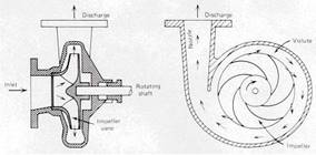
Most pumps used for water distribution systems are of the centrifugal type. These pump water by the action of a spinning impeller inside a volute (casing), which imparts energy to the water, causing it to flow. Because of the way the pump pushes water along, the flow rate is affected by the pressure that must be generated by the pump.
Figure 12: The operation of a centrifugal pump
Bore pumps |
Bore pumps are designed to fit down a narrow hole. They are usually submersible centrifugal pumps designed to be completely submerged in water. They can have single or multiple pumping stages. In a multi-stage pump, a series of impellers are mounted on top of each other to achieve a high pressure. Bore pumps are sensitive to abrasive particles due to the fine clearances needed to achieve a high water pressure. This is why the presence of sand in a bore can affect the operation of the pump. |
Intake pumps |
Intake pumps taking water from rivers and lakes are normally centrifugal pumps designed with large clearances to allow debris to pass through them. |
High-lift pumps for water distribution |
Dry-mounted centrifugal pumps are a good choice for water distribution. ‘Dry-mounted’ simply means the pump is kept dry, with the water piped to and from the pump; only the impeller is immersed in the water. There is less chance of the pump leaking fluid and contaminating the water, and it is easier to work on the pump. Often several pumps operate together to maintain a range of water flows, with individual pumps shutting down when they are not needed. |
Dosing pumps |
Dosing pumps are small pumps designed to accurately feed a liquid chemical at the desired flow rate. For example, this chemical could be sodium hypochlorite for disinfection, or alum for coagulation. They tend to be positive displacement pumps. This means they operate by trapping a fixed amount of fluid and forcing the trapped volume into the discharge pipe. |
The reliability of a system can be improved by providing back-up pumps. These may be spare pumps that are kept in storage, or stand-by pumps plumbed permanently into the system.
For non-critical pumping installations, a suitable strategy may be to have spare pumps available for connection to the system in the event of pump failure. This will be cheaper than permanently installing a second ‘stand-by’ pump. The downfall of operating a system in this way is the time required to remove the existing pump and to install the spare. The water supply network would need to be designed to accommodate the downtime without undue interruption to the supply.
Better reliability can be achieved by providing stand-by pumps that are a permanent part of the water distribution system. The pump that is operating is called the ‘duty’ pump, and the pump waiting to be used is called the ‘stand-by’ pump. When maintenance is required, one pump can be turned off or removed while the other keeps the system operating. Most control systems will alternate use of the pumps so that both pumps run for a similar amount of time.
An alternative configuration allows both pumps to operate together to achieve higher flows at times of peak demand. The system must then make do with reduced flows when a pump is unavailable. This configuration is often described as ‘duty – assist’. The same principles apply to pump systems that include more than two pumps.
A strategy is normally needed for coping with loss of power to the pumps in a distribution system. In many cases there is sufficient water stored in a high-level reservoir to provide water if a power cut occurs. When this is not the case, emergency power generation may be needed. For small pumps this may be as simple as unplugging the pump and plugging it into a portable petrol-driven generator. For larger pumps, which need to remain available at all times, it may be necessary to install a permanent emergency generator system that starts automatically in the event of power failure.
When relying on a portable generator stored off-site it is important to consider the delay in response from the time the outage occurs until the emergency back-up is available.
Advice on the selection of a pump, how to install it and the best place to put it should be sought from an appropriately qualified person (ie, an engineer or technician with reticulation design experience).
The most common use for valves in a distribution system is to isolate sections of pipe so that repairs can be made. Valves used for this purpose are often called ‘isolation valves’. As well as allowing repairs to be made, isolation valves also allow flushing to be carried out effectively and-fire fighting water to be accessed.
Other important valves include fire hydrants, pressure-reducing valves and air valves.
Gate valves are the most common valves in distribution systems operated by local authorities. Gate valves have a solid plate that slides down to block the flow of water. When the valve is opened (by raising the plate), there is no obstruction to the flow of water through the valve.
Figure 13: A gate valve
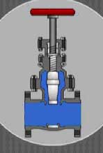
Resilient-seated gate valves have a rubber coating on the gate or the wall the gate touches when it is closed. The rubber coating improves the seal and prevents damage to the valve when there is debris in the pipe.
Knife-gate valves have a narrow gate, which makes the valves smaller and easier to fit into tight spaces. They are generally not suitable for burying in the ground, which makes them less useful for water distribution systems.
Gate valves are often called ‘sluice valves’ when they are resilient seated and the valve is 100 mm diameter or larger.
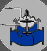
Globe valves work by pushing a hemispherical globe or circular plate against a hole. The edge of the hole where the globe contacts when closed is called the valve seat. Most household taps and stop cocks are globe valves.
Figure 14: A globe valve

A butterfly valve has a round, flat plate that is mounted on a shaft that passes directly through the middle of the valve body. By turning the shaft through 90º the plate is rotated to seal off the flow.
Figure 15: A butterfly valve
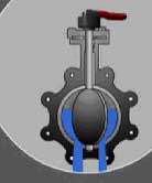
Butterfly valves are cheaper than gate valves. They are not commonly used in local authority water distribution systems but they are common around water treatment plants. Pipelines with butterfly valves in them cannot be swabbed, and serious water hammer can occur if a butterfly valve is opened or closed too quickly.
Fire hydrants are typically a globe valve in an epoxy-coated cast-iron body. A fire hydrant is designed to shut off completely for long periods of time, but when required they must reliably open and provide a high flow at a low pressure drop. Due to the flows and pressures required, fire hydrants are seldom installed on pipes of less than 100 mm nominal bore.
Hydrants should be placed at dead ends in the network to allow these areas to be flushed (see section 12.1.3).
Pressure-reducing valves are normally used when the distribution system is in a hilly area and the effect of gravity means that pressures are too high for customers living at low elevations. Pressure-reducing valves allow different pressure zones to be created for each elevation.
Figure 16: A pressure-reducing valve
Because leakage rates increase with pressure, reducing the system pressure in this way can also save water.
Air relief valves are installed at high points of long water pipes to release the air that gathers in these places. Allowing air to collect can significantly reduce the flow capacity of the pipeline. Fire hydrants or small gate valves can also be used to manually remove this air.
Low-pressure pipelines, such as some trunk mains, may need vacuum relief valves. These valves let air into the pipeline to protect the pipeline from negative pressures that would otherwise collapse the pipe when it empties.
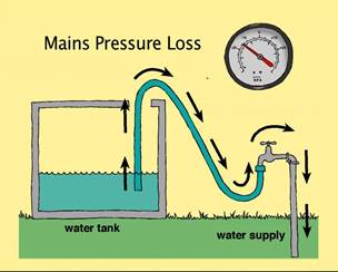
Backflow is the unwanted flow of a liquid or a contaminant back into the potable public water supply. It is caused by a loss of pressure in the distribution network, causing a reversal in the flow of water, or by accidental pumping into the main. Backflow prevention methods stop this contaminated water from entering the distribution system.
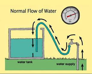
Backsiphon is the most common type of backflow. A reduction of pressure in the water supply creates a vacuum in the piping and the water flows in the reverse direction. For example, imagine a water tank being filled with a hose, as shown in Figure 17. If a sudden failure in the water main causes a reduction of pressure, the water from the tank could be siphoned back into the distribution system. The water in this tank could easily be contaminated: it could be a stock trough, or a tank in which chemicals are being diluted.
Figure 17: Backsiphon from a tank
 |
|
Backpressure occurs when water or contaminants are being used at a higher pressure than the mains supply, and there is a cross connection to the mains. An example would be where mains water is connected as a top-up supply to a boiler that is chemically treated. If the boiler water pressure exceeds the mains supply pressure, the water could be forced back into the mains supply, contaminating it with the chemicals from the boiler.
Devices can be installed to prevent backflow. The choice of device depends on the risk the hazard represents to the water supply. Risks are categorised as follows:
Backflow prevention at property boundaries is particularly important in unchlorinated networks where there is no protection against recontamination.
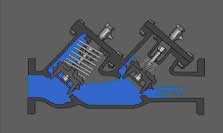
Three devices that can be used are described below.
Figure 18: Types of backflow prevention
Air gap 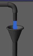 |
An air gap prevents the reverse flow of water. The gap should be at least twice the pipe diameter but not less than 25 mm. There should also be an overflow with a capacity of at least the inflow capacity. |
|
Double-check valve |
Double-check valves close to prevent reverse flow. They provide much better protection than single-check valves. Double check valves that are not able to be tested are only suitable for low-risk applications. Double-check valves that can be tested are suitable for medium-risk applications. |
|
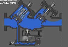
Reduced-pressure-zone device |
Reduced-pressure-zone devices have additional protection over a double-check valve. They are suitable for use in high-risk situations. |
|
Note: This information given in this section is purely introductory. For further information on backflow prevention seek professional advice.
Flow meters are used on bulk water to measure how much water is being used or produced. Regular meter reading gives the water supplier a picture of daily, weekly and yearly demand. Monitoring water usage can also help to detect leakage in a network (see section 12.1.4).
Water meters may also be installed at service connections to provide a basis for charging. The meters are installed at the property owner’s boundary, downstream of the stopcock. Charging based on consumption normally reduces overall water use. Generally, commercial and industrial consumers are metered, even where domestic consumers are not.
A number of different flow meters are available for various metering applications. Two types of flow meter are normally used in public water supplies:
Electromagnetic meters are usually only used in larger networks due to the requirement for on-site power and the high cost of the meters.
Bulk flow meters are used to monitor large flows in or out of storage reservoir sites or the flow leaving a treatment facility or pumping station. They can also be used to monitor abstraction from a water source such as a bore or a river intake.
Commercial meters are installed to monitor water supply into a commercial property for billing purposes. The meter can also be used to identify possible leakage on internal pipework within the customer’s boundary.
Domestic meters are installed at the boundaries of residential properties to monitor water usage into a property. They are used to determine monthly water billing for the property but can also be useful for identifying leakage inside a property. Domestic meters help to reduce water demands in a network because consumers become more aware of water usage.
Distribution systems need to be operated to ensure the water keeps flowing and it is safe and pleasant to drink. This section describes work that is specific to the distribution system. General operation and maintenance tasks are covered in the booklet Operation and Maintenance of a Small Water Supply.
The maintenance of water supply pipework is complicated by the fact that the pipes are normally buried, so problems may not be noticed immediately and are harder to fix. Typical tasks include monitoring water quality, testing for leaks, repairing damaged pipes and flushing the network.
When water is disinfected using chlorine, the chlorine concentration through the distribution system needs to be checked regularly to ensure it remains sufficient. The chlorine dose may need to be adjusted to ensure the target disinfectant residual is maintained.
Levels can fall where the water lies stagnant (such as at dead ends in the pipework), where pipes are much larger than they need to be, or in off-peak times where the population is very seasonal. Generally, routine flushing of a network can help to reduce stagnation of water at dead ends or in oversized networks.
Other water quality issues relating to the pipework may need to be monitored, such as biofilm development and the release of material from corroding pipes. Both issues affect the palatability of the water.
Pipe repairs need to be completed in a way that protects the quality and safety of the water. This section emphasises some of these quality and safety aspects.
In order to complete a repair the damaged area of pipe needs to be isolated. Usually this is achieved by closing the valves on either side. The downstream valve is always closed first in order to maintain positive pressure along the line to prevent backflow.
A damaged section of pipe can be repaired by installing a flexible clamp or sleeve, or by cutting out the damaged section and installing a new piece of pipe (normally with mechanical connections at either end).
High standards of hygiene are needed during a repair. Whenever practicable, all repairs should be done under dry conditions. Corrosion and dirt should be cleaned from the surface of the clamp and sleeve, or the new pipe, before the surfaces are disinfected using industrial-strength bleach. The disinfectant should be applied to all of the wet surfaces of pipes and fittings.
Once the repair is completed, the pipe section that has been isolated should be flushed through with water to remove any contaminants. After flushing, the isolation valves can be opened so that the repaired pipe can be inspected for leaks before being backfilled.
A significant pipe replacement should ideally be tested at a higher pressure than the pipes will be operated under before being put back into service. This allows any small leaks to be detected and repaired before the pipe is buried again.
Biofilms and debris need to be cleaned from the walls of the pipework from time to time. Water supply pipes are normally cleaned by one of three methods: flushing, air scouring and ‘pigging’.
Flushing involves running very high flows through the pipe to lift and carry away the undesirable material. Velocities of at least 1.5 to 2 m/s are needed for flushing to be effective. The flows are discharged to waste, through a fire hydrant or a valve installed specifically for pipe flushing. Figure 19 shows badly discoloured water being removed by flushing.
Care needs to be taken to ensure the flushing does not simply move dirt and contaminants around the system while clean water is discharged through the fire hydrants. Valves and fire hydrants (or flushing valves) need to be opened and closed in the right combination to be effective. The general approach is to start with the fire hydrant or flushing valve that is closest to the water source and work outwards from there. For example, in the simple network shown in Figure 20, flushing could be undertaken as follows.
Air scouring and ‘pigging’ operate in a similar way to simple flushing. Air scouring involves pumping air into the pipeline to introduce turbulence, which shakes dirt loose. This augments pipe flushing. ‘Pigging’ or ‘swabbing’ are terms for pushing a fluid-propelled object through the pipework to scrape off the dirt. It is normally shaped like a ball or bullet and is called a ‘swab’ or a ‘pig’. The swab can be made of various materials, but foam and plastic are common. Water mains are not normally swabbed if they are less than 150 mm in diameter or constructed of asbestos cement.
Swabbing is the most effective way to clean pipework, followed by air scouring, followed by flushing.
Some water loss through leakage is inevitable in all systems. The leakage is typically from underground pipework and customers’ fittings.
The simplest method for estimating leakage is to monitor the minimum night flows. Clearly the flows should be very low while most people are sleeping. If the minimum night flows are high, or have increased from previous years, the probable cause is leakage. The method becomes more accurate if night flows can be measured in specific areas of the network.
Listening devices are often useful to pin-point the leaks in underground pipework. The simplest listening device is a length of steel rod with an ear piece on the end. These are most effective when resting directly on the pipe. Electronic listening devices may be needed for plastic pipes and more difficult leaks.
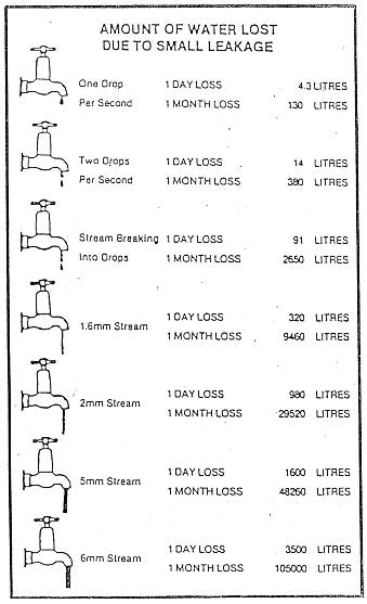
Leakage within the home is important, but hard to control. Figure 21 illustrates the amount of water that can be lost from a single tap over a month for various leakage rates. Even quite small amounts of leakage can easily add up to significant losses over time.
Figure 21: Amount of water lost due to small leakage
Valves on a distribution system are generally not used very often. As a result, problems with valves tend to stem from corrosion and disuse rather than wear. Regular inspection and ‘exercising’ of valves can help ensure the valves will work when they need to. This should be done at least once a year. The following procedure could be used.
1. Check that the valve location is correctly shown on a plan of the system. Add dimensions and additional sketches to ensure the valve can be found in the future.
2. Remove any covers and inspect the top of the valve for damage or obvious leakage.
3. Slowly close the valve fully and record the number of turns to the fully closed position.
4. Reopen the valve to establish system flows. It is normal to avoid leaving a valve in a fully open or fully closed position to help avoid sticking, so back the valve off fully open by a turn or two.
5. Replace the cover.
Typical activities include cleaning the tank, testing for disinfection residual and inspecting the structural condition.
Visual inspection |
The following should be inspected:
|
Water quality testing |
Chlorine residual entering and leaving the tank is an indication of the chlorine demand of the water and the effect of storage time. |
Storage tanks often need regular cleaning to remove accumulated sediment, slimes or chemical deposits. The cleaning needs to be carried out before the accumulated material causes an unacceptable decline in the quality of the water. Cleaning frequencies typically vary between six months and five years.
The tank cleaning procedure should aim to minimise disruption of the water supply. Cleaning generally involves draining the tank, then sweeping and scrubbing the interior surfaces. The tank is then filled with fresh water and sufficient chlorine is added to create a 50 mg/L solution in the tank, which disinfects any contamination that has been introduced. The chlorine solution should remain in the tank for at least six hours (preferably more) before draining and refilling for regular use. Water containing chlorine should not be discharged into a water course because it will kill fish and aquatic life. The chlorine should be neutralised using chemicals that are available for this purpose, such as sodium thiosulphate.
Operator safety cannot be ignored when entering tanks because they are a confined space from which escape is very difficult if the atmosphere becomes unsafe. This could happen as a result of machinery exhaust fumes or other toxic gases that may be released as a result of the particular work being undertaken. Entry needs to follow occupational safety and health requirements, as listed at http://www.osh.govt.nz.
Tanks can still be cleaned successfully when it isn’t practical to drain the tank for cleaning. Often vacuum devices designed for swimming pools are used to remove sediment from small tanks.
Figure 23: Siphon cleaning system
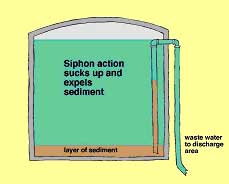
Self-cleaning systems where the tank overflows from the bottom rather than the top are also useful for rain tanks.
Following is a checklist of issues to consider when planning to clean a tank.
þ Can the tank be bypassed, or does the water supply need to be shut down during the cleaning process? Can temporary storage be used?
þ If the water supply will be disrupted, how will customers be notified?
þ How long will it take to drain and clean the tank?
þ Do any other checks or work need to be done while the tank is empty?
þ How long will it take to disinfect the tank before returning it to use?
þ How will the disinfection water be disposed of?
þ How will worker safety be protected?
Ministry of Health Resources for Drinking-water Assistance Programme.
Standards New Zealand 4509: 2008.
See section 7.4.5.
See section 7.4.5.
Ministry of Health, Resources for Drinking Water Assistance Programme.
Source: https://www.health.govt.nz/system/files/documents/publications/pumps-pipes-and-storage2010.doc
Web site to visit: https://www.health.govt.nz/
Author of the text: indicated on the source document of the above text
If you are the author of the text above and you not agree to share your knowledge for teaching, research, scholarship (for fair use as indicated in the United States copyrigh low) please send us an e-mail and we will remove your text quickly. Fair use is a limitation and exception to the exclusive right granted by copyright law to the author of a creative work. In United States copyright law, fair use is a doctrine that permits limited use of copyrighted material without acquiring permission from the rights holders. Examples of fair use include commentary, search engines, criticism, news reporting, research, teaching, library archiving and scholarship. It provides for the legal, unlicensed citation or incorporation of copyrighted material in another author's work under a four-factor balancing test. (source: http://en.wikipedia.org/wiki/Fair_use)
The information of medicine and health contained in the site are of a general nature and purpose which is purely informative and for this reason may not replace in any case, the council of a doctor or a qualified entity legally to the profession.
The texts are the property of their respective authors and we thank them for giving us the opportunity to share for free to students, teachers and users of the Web their texts will used only for illustrative educational and scientific purposes only.
All the information in our site are given for nonprofit educational purposes