
Chapter 2. Moment and Deflections in Cantilever Beams
2-1 What is a Bending Moment?
Chapter 1 dealt with trusses. Trusses are used mainly for large structures such as bridges and domes. In this chapter, we shall study beams, which are used not only in bridges but also in small buildings. A beam is a horizontal member supporting a roof or a floor as shown in Fig. 2-1-1a. A beam that projects out from a building supporting a balcony is called a ‘cantilever beam.’ To understand the phenomenon of bending of beams in simple steps, we shall start by studying strength and deformation properties of a cantilever beam embedded in a rigid wall as shown in Fig. 2-1-1b.
Fig. 2-1-1 Cantilever beam
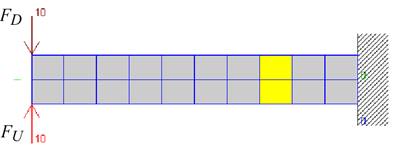
Start ‘GOYA- C’ to reach the window in Fig. 2-1-2 showing a cantilever beam with a load of 10 N at its free end.
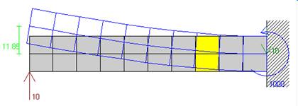
Fig. 2-1-2 Deflected shape of cantilever as seen in first window of GOYA- C
You will find a sliding bar titled ‘Load Magnitude’ at the bottom of the window. Move the bar to the left to obtain -10 N. The beam will deflect down as shown in Fig. 2-1-3.
![]()

![]()
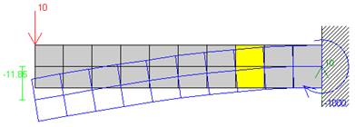
That the beam deflects in the direction of the force appears intuitively correct. How does the beam deflect if it is subjected to the set of forces shown in Fig. 2-1-4a? Which of the four deflected shapes in Fig. 2-1-4b through e would you guess is the correct one? To check your guess, do the following.
1) Click the ‘Add Load’ button to create another load pushing at the end of the beam. The deflection will disappear as shown in Fig. 2-1-5.
2) Click on the downward load and drag it to mid-span as shown in Fig. 2-1-6.
The entire beam deflects up!
![]()
![]()

Fig. 2-1-5 Click ‘Add load’ button

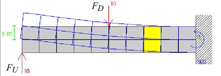
Fig. 2-1-6 Drag the load to mid-span
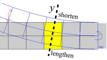
Let us now investigate how the beam bends in detail. Click the ‘Zoom in’ button and type “4” in the text field titled ‘Amplification’ to get the image shown in Fig. 2-1-7. You will find not only that the yellow segment rotates and moves up but also that the top of the yellow segment shortens while the bottom lengthens.
![]()
![]()

Fig. 2-1-7 Click the ‘Zoom in’ button and type “4” in the ‘Amplification’ text-field
Click the ‘Zoom out’ button and type “1” in the ‘Amplification’ text-field. Then, look at the window in the upper right (Fig. 2-1-8) showing the deformation of the highlighted (yellow) segment. This segment has been removed from the beam and rotated so that its y-axis is vertical. Also, the flexural deformations (the shortening of the top and lengthening of the bottom) have been magnified by a factor of ten.
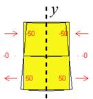 Fig. 2-1-8 Flexural deformation
Why does the top of the segment shorten while the bottom lengthens? The answer can be obtained if you check the ‘ Free-body Diagram’ item in the bottom right to obtain the image shown in Fig. 2-1-9. GOYA-C shows a free-body diagram of the beam to the left of the faded segment (Fig. 2-1-10a). The two external forces tend to rotate the beam at the imaginary cut clockwise (Fig. 2-1-10b). To prevent the rotation, there should be an anti-clockwise action M to the right of the yellow segment. This action is called a ‘bending moment.’ Because the moment is defined as a force multiplied by a distance (see Section 1-6), the magnitude of the bending moment is given by Eq. 2.1.1.
M = F.a (2.1.1)
In GOYA- C, the width of each segment is 10 mm, so that the length between the forces is a = 50 mm (Fig. 2-1-9). From Eq. 2.1.1, the moment M is 500 N-mm (M =F.a= 10 x50=500 N-mm.) Move the location of the forces to the left or to the right to obtain your own perspective of the variations in bending moment and deflected shape of the beam . Recall that the beam deflection increased when you moved the force FD to the right in Fig. 2.1.6, suggesting that an increase of the distance a in Eq. 2.1.1 results in a larger bending moment and larger deflection. Using GOYA-C, test if this suggestion is correct.
Move this force to the left or right.
![]()

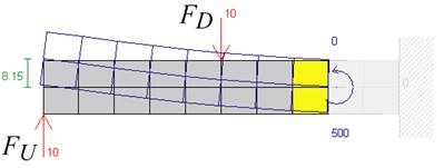
Fig. 2-1-9 Faded segments to the right of the highlighted segment
Fig. 2-1-10 Cut the beam to see equilibrium
Figure 2-1-10c shows a free-body diagram of the beam with the moment M required to balance the moment generated as the product of F and a. The moment M is essentially a couple as illustrated in Fig. 2-1-10d. It comprises two equal and opposite forces at a distance (2/3)h from one another, where h is the beam height . Equilibrium in the horizontal direction requires T = C. The product (2/3)Th or (2/3)Ch is equal to M.
The forces, T and C, cause tensile and compressive deformations of the beam shown in Fig. 2-1-10e. To understand their effect, cut the beam again at the left end of the yellow segment as shown in Fig. 2-1-10f, where equilibrium in the horizontal direction requires the same magnitude of forces at both faces of the segment. These pairs of tensile and compressive forces create moments causing the flexural deformation (i.e. the lengthening at the top and the shortening of the bottom). The moments are represented by round (bent) arrows as shown in Fig. 2-1-10g.
Equilibrium of the beam is similar to that of the truss. Look at the truss in Fig. 2-1-12a. The truss is connected to the wall at the right end and is analogous to the cantilever beam shown in Fig. 2-1-12b. Cutting the truss as shown in Fig. 2-1-12c and considering moment equilibrium, you will find that the top chord carries the tensile force of 50 N and the bottom chord the compressive force of 50 N. This is equivalent to the equilibrium condition depicted in Fig. 2-1-10d.
Fig. 2-1-12 A truss similar to a cantilever beam
Figure 2-1-13 shows the result of the analysis obtained using GOYA-A (where the cross-sectional area of each member is assumed to be 20 mm2). The deflected shape of the truss is also similar to that of the cantilever beam.
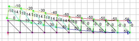
Fig. 2-1-13 Analysis using GOYA-A
Experiment: Make a cantilever beam using a plastic ruler as shown in Fig. 2-1-14, and apply a pair of forces using your thumb and little finger. If you can make the magnitude of the forces equal, the ruler will bend down.
Fig. 2-1-14 Experiment using a plastic ruler
Exercise: Compare Figs. 2-1-15a and b. Which beam has larger bending moment at the highlighted segment? Which beam deflects more?
Fig. 2-1-15 Bending moment
Answer: The bending moments are the same because the distances between the vertical forces are the same. However, because beam (a) has a longer deformed region than beam (b) does, the deflection of beam (a) is more than that of beam (b).
Exercise using GOYA-C: Click the ‘Details of Beam’ button to obtain the window below specifying the length, width and height of the beam. Change the height to 7.5 mm, click the ‘update’ button, and click the main window. You will obtain Fig. 2-1-17. Note that the tensile and compressive forces on the yellow segment double from 50 N to 100 N because the distance between the forces ((2/3)h in Fig. 2-1-11) is halved from 10 mm to 5 mm, while the bending moment M = T.(2/3)h remains the same. The increase of the forces causes larger flexural deformation (8 times). This phenomenon will be discussed in Section 2-8.
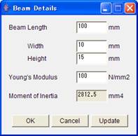
Fig. 2-1-16 Window specifying the details of the beam
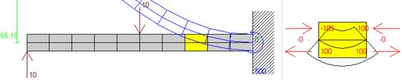
Fig. 2-1-17 Beam with smaller height
Design your own beam (Part 1)
We want to design a beam complying with the following conditions.
1. The magnitude of the forces shall be the last digit of your ID# plus 10 N.
2. The distance between the forces shall be the last digit of your ID# plus 30 mm.
3. The tensile force in the beam shall not exceed 50 N.
What is the required beam height? Check your result using GOYA-C.
Fig. 2-1-18 Your beam
 Bending moment is an action that bends a beam.
Bending moment and deformation
![]() Hi, Joan. I still do not understand the action of a bending moment. I know that a tensile axial force elongates each atom in a member. Does a bending moment bend each atom?
Hi, Joan. I still do not understand the action of a bending moment. I know that a tensile axial force elongates each atom in a member. Does a bending moment bend each atom?
![]() No, it does not. Each atom in a bent member has a pair of tensile or compressive forces so that it elongates or shortens. The uppermost atom has the largest tensile forces, while the lowermost atom has the largest compressive force.
No, it does not. Each atom in a bent member has a pair of tensile or compressive forces so that it elongates or shortens. The uppermost atom has the largest tensile forces, while the lowermost atom has the largest compressive force.
![]() Hmm, if each atom elongates or shortens, the beam must be a trapezoid, and will not bend, I believe.
Hmm, if each atom elongates or shortens, the beam must be a trapezoid, and will not bend, I believe.
![]() Not true. Each atom is so small that to understand what is happening you should slice the beam very thin slices. Each slice will be a trapezoid, and the beam will bend. Bend your eraser with your fingers. You will observe flexural deformation.
Not true. Each atom is so small that to understand what is happening you should slice the beam very thin slices. Each slice will be a trapezoid, and the beam will bend. Bend your eraser with your fingers. You will observe flexural deformation.
![]()
By the way, I don’t like your figure. Atoms do not deform in reality. The structure among the atoms deforms.
![]()
Don’t worry. I like it.
Source: ftp://ftp.ecn.purdue.edu/sozen/ZEN/ZEN/2-1%20Bending-sozen.doc
Web site to visit: ftp://ftp.ecn.purdue.edu
Author of the text: indicated on the source document of the above text
If you are the author of the text above and you not agree to share your knowledge for teaching, research, scholarship (for fair use as indicated in the United States copyrigh low) please send us an e-mail and we will remove your text quickly. Fair use is a limitation and exception to the exclusive right granted by copyright law to the author of a creative work. In United States copyright law, fair use is a doctrine that permits limited use of copyrighted material without acquiring permission from the rights holders. Examples of fair use include commentary, search engines, criticism, news reporting, research, teaching, library archiving and scholarship. It provides for the legal, unlicensed citation or incorporation of copyrighted material in another author's work under a four-factor balancing test. (source: http://en.wikipedia.org/wiki/Fair_use)
The information of medicine and health contained in the site are of a general nature and purpose which is purely informative and for this reason may not replace in any case, the council of a doctor or a qualified entity legally to the profession.
The texts are the property of their respective authors and we thank them for giving us the opportunity to share for free to students, teachers and users of the Web their texts will used only for illustrative educational and scientific purposes only.
All the information in our site are given for nonprofit educational purposes