
When the diameter of a piece changes uniformly from one end to the other, the piece is said to be tapered. Taper turning as a machining operation is the gradual reduction in diameter from one part of a cylindrical workpiece to another part. Tapers can be either external or internal. If a workpiece is tapered on the outside, it has an external taper; if it is tapered on the inside, it has an internal taper. There are three basic methods of turning tapers with a lathe. Depending on the degree, length, location of the taper (internal or external), and the number of pieces to be done, the operator will either use the compound rest, offset the tailstock, or use the taper attachment. With any of these methods the cutting edge of the tool bit must be set exactly on center with the axis of the workpiece or the work will not be truly conical and the rate of taper will vary with each cut.
Compound Rests
The compound rest is favorable for turning or boring short, steep tapers, but it can also be used for longer, gradual tapers providing the length of taper does not exceed the distance the compound rest will move upon its slide. This method can be used with a high degree of accuracy, but is somewhat limited due to lack of automatic feed and the length of taper being restricted to the movement of the slide.
The compound rest base is graduated in degrees and can be set at the required angle for taper turning or boring. With this method, it is necessary to know the included angle of the taper to be machined. The angle of the taper with the centerline is one-half the included angle and will be the angle the compound rest is set for. For example, to true up a lathe center which has an included angle of 60°, the compound rest would be set at 30° from parallel to the ways (Figure 7-41).
If there is no degree of angle given for a particular job, then calculate the compound rest setting by finding the taper per inch, and then calculating the tangent of the angle (which is the: compound rest setting) .
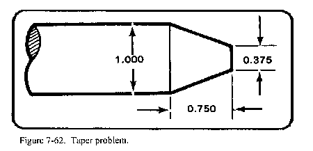
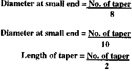
For example, the compound rest setting for the workpiece shown in Figure 7-62 would be calculated in the following manner
![]()
Where TPI = taper per inch
D |
= |
large diameter, |
|
||
d |
= |
small diameter, |
|
||
L |
= |
length of taper |
|
||
angle |
= |
compound rest setting |
The problem is actually worked out by substituting numerical values for the letter variables:
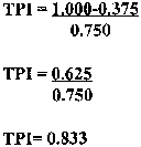
Apply the formula to find the angle by substituting the numerical values for the letter variables:
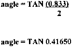
Using the trig charts in TC 9-515 or any other source of trig charts, the TAN of 0.41650 is found to be 22 ؛37 '. This angle is referred to as 22 degrees and 37 minutes.
To machine the taper shown in Figure 7-62, the compound rest will be set at 22°37 '. Since the base of the compound rest is not calibrated in minutes, the operator will set the base to an approximate degree reading, make trial cuts, take measurements, and readjust as necessary to obtain the desired angle of taper. The included angle of the workpiece is double that of the tangent of angle (compound rest setting). In this case, the double of 22°37' would equal the included angle of 45°14'.
To machine a taper by this method, the tool bit is set on center with the workpiece axis. Turn the compound rest feed handle in a counterclockwise direction to move the compound rest near its rear limit of travel to assure sufficient traverse to complete the taper. Bring the tool bit into position with the workpiece by traversing and cross-feeding the carriage. Lock the carriage to the lathe bed when the tool bit is in position. Cut from right to left, adjusting the depth of cut by moving the cross feed handle and reading the calibrated collar located on the cross feed handle. feed the tool bit by hand-turning the compound rest feed handle in a clockwise direction.
Offsetting the Tailstock
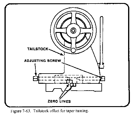
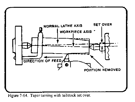
The oldest and probably most used method of taper turning is the offset tailstock method. The tailstock is made in two pieces: the lower piece is fitted to the bed, while the upper part can be adjusted laterally to a given offset by use of adjusting screws and lineup marks (Figure 7-63).
Since the workpiece is mounted between centers, this method of taper turning can only be used for external tapers. The length of the taper is from headstock center to tailstock center, which allows for longer tapers than can be machined using the compound rest or taper attachment methods.
The tool bit travels along a line which is parallel with the ways of the lathe. When the lathe centers are aligned and the workpiece is machined between these centers, the diameter will remain constant from one end of the piece to the other. If the tailstock is offset, as shown in Figure 7-64, the centerline of the workpiece is no longer parallel with the ways; however, the tool bit continues its parallel movement with the ways, resulting in a tapered workpiece. The tailstock may be offset either toward or away from the operator. When the offset is toward the operator, the small end of the workpiece will be at the tailstock with the diameter increasing toward the headstock end.
The offset tailstock method is applicable only to comparatively gradual tapers because the lathe centers, being out of alignment, do not have full bearing on the workpiece. Center holes are likely to wear out of their true positions if the lathe centers are offset too far, causing poor results and possible damage to centers.
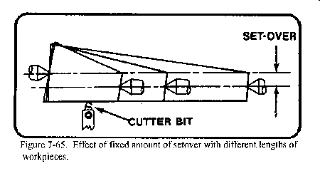
The most difficult operation in taper turning by the offset tailstock method is determining the proper distance the tailstock should be moved over to obtain a given taper. Two factors affect the amount the tailstock is offset: the taper desired and the length of the workpiece. If the offset remains constant, workpieces of different lengths, or with different depth center holes, will be machined with different tapers (Figure 7-65).
The formula for calculating the tailstock offset when the taper is given in taper inches per foot (tpf) is as follows
![]()
Where: Offset |
= |
tailstock offset (in inches) |
TPF |
= |
taper (in inches per foot) |
L |
= |
length of taper (in feet) measured along the axis of the workpiece |
For example, the amount of offset required to machine a bar 42 inches (3.5 feet) long with a taper of 1/2 inch per foot is calculated as follows:
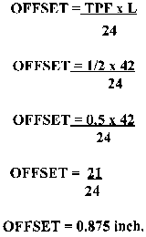
Therefore, the tailstock should be offset 0.875 inch to machine the required taper. The formula for calculating the tailstock offset when the taper is given in TPF is as follows:
![]()
Where OFFSET |
= |
tailstock offset |
TPI |
= |
taper per inch |
L |
= |
length of taper in inches |
For example, the amount of offset required to machine a bar 42 inches long with a taper of 0.0416 TPI is calculated as follows:
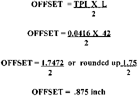
Therefore, the tailstock should be offset 0.875 inch to machine the required taper.
If the workpiece has a short taper in any par of it's length and the TPI or TPF is not given, use the following formula:
![]()
Where :
D = Diameter of large end
d = Diameter of small end
L = Total length of workpiece in inches diameter (in inches)
L1 = Length of taper
For example, the amount of tailstock offset required to machine a bar 36 inches (3 feet) in length for a distance of 18 inches (1.5 feet) when the large diameter is 1 3/4 (1 .750) inches and the small diameter is 1 1/2 (1.5) inches is calculated as follows
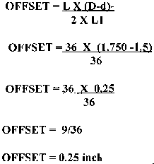
Therefore, the tailstock would be offset (toward the operator) 0.25 inch to machine the required taper.
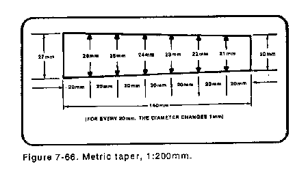
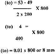
Metric tapers can also be calculated for taper turning by using the offset tailstock method. Metric tapers are expressed as a ratio of 1 mm per unit of length. Figure 7-66 shows how the work would taper 1 mm in a distance of 20 mm. This taper would then be given as a ratio of 1:20 and would be annotated on small diameter (d) will be 1 mm greater (d + ). Refer to the following formula for calculating the dimensions of a metric taper. If the small diameter (d), the unit length of taper (k), and the total length of taper (1) are known, then the large diameter (D) may be calculated. The large diameter (D) will be equal to the small diameter plus the amount of taper. The amount of taper for the unit length (k) is (d + 1) -(d). Therefore, the amount of taper per millimeter of unit length = (l/k). The total amount of taper will be the taper per millimeter (l/k) multiplied by the total length of taper (l).
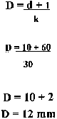
For example, to calculate for the large diameter D for a 1:30
![]()
taper having a small diameter of 10 mm and a length of 60 mm, do the following:
Since the taper is the ratio 1:30, then (k)= 30, since 30 is the unit of length.
Tailstock offset is calculated as follows:
Tailstock offset = |
|
D |
= large diameter |
d |
= small diameter |
I |
= length of taper |
L |
= length of the workpiece |
Thus, to determine the tailstock offset in millimeters for the taper in Figure 7-67, substitute the numbers and solve for the offset. Calculate the tailstock offset required to turn a 1:50 taper 200 mm long on a workpiece 800 mm long. The small diameter of the tapered section is 49 mm.
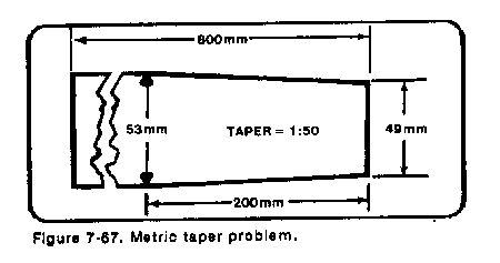
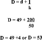
The tailstock would be moved toward the operator 8 mm.
Another important consideration in calculating offset is the distance the lathe centers enter the workpiece. The leng
th of the workpiece (L) should be considered as the distance between the points of the centers for all offset computations.
Therefore, if the centers enter the workpiece 1/8 inch on each end and the length of the workpiece is 18 inches, subtract 1/4 inch from 18 inches and compute the tailstock offset using 17 3/4 inches as the workpiece length (L).
The amount of taper to be cut will govern the distance the top of the tailstock is offset from the centerline of the lathe. The tailstock is adjusted by loosening the clamp nuts, shifting the upper half of the tailstock with the adjusting screws, and then tightening them in place.
There are several methods the operator may use to measure the distance the tailstock has been offset depending upon the accuracy desired (Figure 7-68 ).
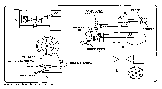
One method is to gage the distance the lineup marks on the rear of the tailstock have moved out of alignment. This can be done by using a 6-inch rule placed near the lineup marks or by transferring the distance between the marks to the rule's surface using a pair of dividers.
Another common method uses a rule to check the amount of offset when the tailstock is brought close to the headstock.
Where accuracy is required, the amount of offset may be measured by means of the graduated collar on the cross feed screw. First compute the amount of offset; next, set the tool holder in the tool post so the butt end of the holder faces the tailstock spindle. Using the cross feed, run the tool holder in by hand until the butt end touches the tailstock spindle. The pressure should be just enough to hold a slip of paper placed between the tool holder and the spindle. Next, move the cross slide to bring the tool holder toward you to remove the backlash. The reading on the cross feed micrometer collar may be recorded, or the graduated collar on the cross feed screw may be set at zero. Using either the recorded reading or the zero setting for a starting point, bring the cross slide toward you the distance computed by the offset. Loosen and offset the tailstock until the slip of paper drags when pulled between the tool holder and the spindle. Clamp the tailstock to the lathe bed.
Another and possibly the most precise method of measuring the offset is to use a dial indicator. The indicator is set on the center of the tailstock spindle while the centers are still aligned. A slight loading of the indicator is advised since the first 0.010 or 0.020 inches of movement of the indicator may be inaccurate due to mechanism wear causing fluctuating readings. Load the dial indicators follows: Set the bezel to zero and move tailstock towards the operator the calculated Famount. Then clamp the tailstock to the way.
Whichever method is used to offset the tailstock, the offset must still be checked before starting to cut. Set the dial indicator in the tool post with its spindle just barely touching far right side of the workpiece. Then, rotate the carriage toward the headstock exactly 1 inch and take the reading from the dial indicator. One inch is easily accomplished using the thread chasing dial. It is 1 inch from one number to another.
Alternatively, 1 inch can be drawn out on the workpiece. The dial indicator will indicate the taper for that 1 inch and, if needed, the tailstock can be adjusted as needed to the precise taper desired. If this method of checking the taper is not used, then an extensive trial and error method is necessary.
To cut the taper, start the rough turning at the end which will be the small diameter and feed longitudinally toward the large end (Figure 7-64). The tailstock is offset toward the operator and the feed will be from right to left. The tool bit, a right-hand turning tool bit or a round-nose turning tool bit, will have its cutting edge set exactly on the horizontal centerline of the workpiece, not above center as with straight turning.
Taper Attachment
The taper attachment (Figure 7-69 ) has many features of special value, among which are the following:
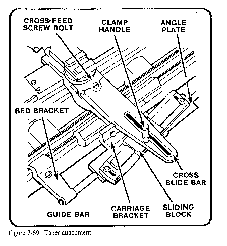
Some engine lathes are equipped with a taper attachment as standard equipment and most lathe manufacturers have a taper attachment available. Taper turning with a taper attachment, although generally limited to a taper of 3 inches per foot and to a set length of 12 to 24 inches, affords the most accurate means for turning or boring tapers. The taper can be set directly on the taper attachment in inches per foot; on some attachments, the taper can be set in degrees as well.
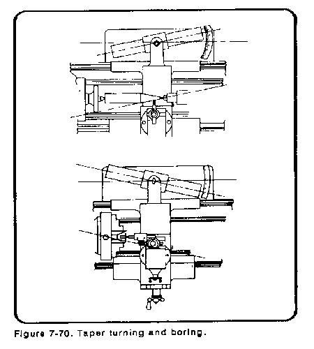
Ordinarily, when the lathe centers are in line, the work is turned straight, because as the carriage feeds along, the tool is always the same distance from the centerline. The purpose of the taper attachment is to make it possible to keep the lathe centers in line, but by freeing the cross slide and then guiding it (and the tool bit) gradually away from the centerline, a taper can be cut or, by guiding it gradually nearer the centerline (Figure 7-70), a taper hole can be bored.
A plain taper attachment for the lathe is illustrated in Figure 7-69. A bed bracket attaches to the lathe bed and keeps the angle plate from moving to the left or the right. The carriage bracket moves along the underside of the angle plate in a dovetail and keeps the angle plate from moving in or out on the bed bracket. The taper to be cut is set by placing the guide bar, which clamps to the angle plate, at an angle to the ways of the lathe bed. Graduations on one or both ends of the guide bar are used to make this adjustment. A sliding block which rides on a dovetail on the upper surface of the guide bar is secured during the machining operation to the cross slide bar of the carriage, with the cross feed screw of the carriage being disconnected. Therefore, as the carriage is traversed during the feeding operation, the cross slide bar follows the guide bar, moving at the predetermined angle from the ways of the bed to cut the taper. It is not necessary to remove the taper attachment when straight turning is desired. The guide bar can be set parallel to the ways, or the clamp handle can be released permitting the sliding block to move without affecting the cross slide bar, and the cross feed screw can be reengaged to permit power cross feed and control of the cross slide from the apron of the carriage.
Modern lathes use a telescopic taper attachment. This attachment allows for using the cross feed, and set up is a bit faster than using a standard taper attachment. To use the telescopic attachment, first set the tool bit for the required diameter of the work and engage the attachment by tightening the binding screws, the location and number of which depend upon the design of the attachment. The purpose of the binding screws is to bind the cross slide so it may be moved only by turning the cross feed handle, or, when loosened, to free the cross slide for use with the taper attachment. To change back to straight turning with the telescopic attachment, it is necessary only to loosen the binding screws.
When cutting a taper using the taper attachment, the direction of feed should be from the intended small diameter toward the intended large diameter. Cutting in this manner, the depth of cut will decrease as the tool bit passes along the workpiece surface and will assist the operator in preventing possible damage to the tool bit, workpiece, and lathe by forcing too deep a cut.
The length of the taper the guide bar will allow is usually not over 12 to 24 inches, depending on the size of the lathe. It is possible to machine a taper longer than the guide bar allows by moving the attachment after a portion of the desired taper length has been machined; then the remainder of the taper can be cut. However, this operation requires experience.
If a plain standard taper attachment is being used, remove the binding screw in the cross slide and set the compound rest perpendicular to the ways. Use the compound rest graduated collar for depth adjustments.
When using the taper attachment, there may be a certain amount of "lost motion" (backlash) which must be eliminated or serious problems will result. In every slide and every freely revolving screw there is a certain amount of lost motion which is very noticeable if the parts are worn. Care must be taken to remove lost motion before proceeding to cut or the workpiece will be turned or bored straight for a short distance before the taper attachment begins to work. To take up lost motion when turning tapers, run the carriage back toward the dead center as far as possible, then feed forward by hand to the end of the workpiece where the power feed is engaged to finish the cut. This procedure must be repeated for every cut.
The best way to bore a taper with a lathe is to use the taper attachment. Backlash must be removed when tapers are being bored with the taper attachment, otherwise the hole will be bored straight for a distance before the taper starts. Two important factors to consider: the boring tool must be set exactly on center with the workpiece axis, and it must be small enough in size to pass through the hole without rubbing at the small diameter. A violation of either of these factors will result in a poorly formed, inaccurate taper or damage to the tool and workpiece. The clearance of the cutter bit shank and boring tool bar must be determined for the smaller diameter of the taper. Taper boring is accomplished in the same manner as taper turning.
To set up the lathe attachment for turning a taper, the proper TPF must be calculated and the taper attachment set-over must be checked with a dial indicator prior to cutting. Calculate the taper per foot by using the formula:
![]()
TPF = taper per foot, |
D = large diameter (in inches), |
d = small diameter (in inches), |
L = length of taper |
After the TPF is determined, the approximate angle can be set on the graduated TPF scale of the taper attachment. Use a dial indicator and a test bar to set up for the exact taper. Check the taper in the same manner as cutting the taper by allowing for backlash and moving the dial indicator along the test bar from the tailstock end of the head stock end. Check the TPI by using the thread-chasing dial, or using layout lines of 1-inch size, and multiply by 12 to check the TPF. Make any adjustments needed, set up the work to be tapered, and take a trial cut. After checking the trial cut and making final adjustments, continue to cut the taper to required dimensions as in straight turning. Some lathes are set up in metric measurement instead of inch measurement. The taper attachment has a scale graduated in degrees, and the guide bar can be set over for the angle of the desired taper. If the angle of the taper is not given, use the following formula to determine the amount of the guide bar set over:
Guide Bar Set Over (in millimeters) = |
|
D = large diameter of taper (mm)
d = small diameter of taper (mm)
I = length of taper (mm)
L = length of guide bar (mm)
Reference lines must be marked on the guide bar an equal distance from the center for best results.
A metric dial indicator can be used to measure the guide bar set over, or the values can be changed to inch values and an inch dial indicator used.
Checking Tapers for Accuracy
Tapers must be checked for uniformity after cutting a trial cut. Lay a good straight edge along the length of the taper and look for any deviation of the angle or surface. Deviation is caused by backlash or a lathe with loose or worn parts. A bored taper may be checked with a plug gage (Figure 7-71) by marking the gage with chalk or Prussian blue pigment. Insert the gage into the taper and turn it one revolution. If the marking on the gage has been rubbed evenly, the angle of taper is correct. The angle of taper must be increased when there is not enough contact at the small end of the plug gage, and it must be decreased when there is not enough contact at the large end of the gage. After the correct taper has been obtained but the gage does not enter the workpiece far enough, additional cuts must be taken to increase the diameter of the bore.
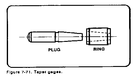
An external taper may be checked with a ring gage (Figure 7-71). This is achieved by the same method as for checking internal tapers, except that the workpiece will be marked with the chalk or Prussian blue pigment rather than the gage. Also, the angle of taper must be decreased when there is not enough contact at the small end of the ring gage and it must be increased when there is not enough contact at the large end of the gage. If no gage is available, the workpiece should be tested in the hole it is to fit. When even contact has been obtained, but the tapered portion does not enter the gage or hole far enough, the diameter of the piece is too large and must be decreased by additional depth of cut
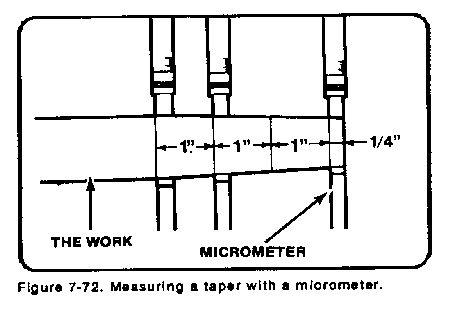
Another good method of checking external tapers is to scribe lines on the workpiece 1 inch apart (Figure 7-72); then, take measurements with an outside micrometer. Subtracting the small reading from the large reading will give the taper per inch.
Duplicating a Tapered Piece
When the taper on a piece of work is to be duplicated and the original piece is available, it may be placed between centers on the lathe and checked with a dial indicator mounted in the tool post.. When the setting is correct, the dial indicator reading will remain constant when moved along the length of taper.
This same method can be used on workpieces without centers provided one end of the workpiece can be mounted and held securely on center in the headstock of the lathe. For example, a lathe center could be mounted in the lathe spindle by use of the spindle sleeve, or a partially tapered workpiece could be held by the nontapered portion mounted in a collet or a chuck. Using either of these two methods of holding the work, the operator could use only the compound rest or the taper attachment for determining and machining the tapers.
There are various standard tapers in commercial use, the most common ones being the Morse tapers, the Brown and Sharpe tapers, the American Standard Machine tapers, the Jarno tapers, and the Standard taper pins.
Morse tapers are used on a variety of tool shanks, and exclusively on the shanks of twist drills. The taper for different numbers of Morse tapers is slightly different, but is approximately 5/8 inch per foot in most cases. Dimensions for Morse tapers are given in Table 7-4 in Appendix A.
Brown and Sharpe tapers are used for taper shanks on tools such as end mills and reamers. The taper is approximately ½ inch per foot for all sizes except for taper No 10, where the taper is 0.5161 inch per foot.
The American Standard machine tapers are composed of a self-holding series and a steep taper series. The self-holding taper series consists of 22 sizes which are given in Table 7-5 in Appendix A. The name "self-holding" has been applied where the angle of the taper is only 2° or 3° and the shank of the tool is so firmly seated in its socket that there is considerable frictional resistance to any force tending to. turn or rotate the tool in the holder. The self-holding tapers are composed of selected tapers from the Morse, the Brown and Sharpe, and the ¾-inch-per foot machine taper series. The smaller sizes of self-holding tapered shanks are provided with a tang to drive the cutting tool. Larger sizes employ a tang drive with the shank held by a key, or a key drive with the shank held with a draw bolt. The steep machine tapers consist of a preferred series and an intermediate series as given in Table 7-6 in Appendix A. A steep taper is defined as a taper having an angle large enough to ensure the easy or self-releasing feature. Steep tapers have a 3 ½-inch taper per foot and are used mainly for aligning milling machine arbors and spindles, and on some lathe spindles and their accessories.
The Jarno taper is based on such simple formulas that practically no calculations are required when the number of taper is known. The taper per foot of all Jarno tapers is 0.600 inch per foot. The diameter at the large end is as many eighths, the diameter at the small end is as many tenths, and the length as many half-inches as indicated by the number of the taper. For example: A No 7 Jarno taper is 7/8 inch in diameter at the large end; 7/10 or 0.7 inch in diameter at the small end; and 7/2, or 3 ½ inches long. Therefore, formulas for these dimensions would read:
The Jarno taper is used on various machine tools, especially profiling machines and die-sinking machines. It has also been used for the headstock and tailstock spindles on some lathes.
The Standard taper pins are used for positioning and holding parts together and have a ¼-inch taper per foot. Standard sizes in these pins range from No 7/0 to No 10 and are given in Table 7-7 in Appendix A. The tapered holes used in conjunction with the tapered pins utilize the processes of step-drilling and taper reaming.
To preserve the accuracy and efficiency of tapers (shanks and holes), they must be kept free from dirt, chips, nicks, or burrs. The most important thing in regard to tapers is to keep them clean. The next most important thing is to remove all oil by wiping the tapered surfaces with a soft, dry cloth before use, because an oily taper will not hold.
Source: http://faculty.ksu.edu.sa/hossainy/Book1/Chapter%207.doc
Web site to visit:http://faculty.ksu.edu.sa
Author of the text: indicated on the source document of the above text
If you are the author of the text above and you not agree to share your knowledge for teaching, research, scholarship (for fair use as indicated in the United States copyrigh low) please send us an e-mail and we will remove your text quickly. Fair use is a limitation and exception to the exclusive right granted by copyright law to the author of a creative work. In United States copyright law, fair use is a doctrine that permits limited use of copyrighted material without acquiring permission from the rights holders. Examples of fair use include commentary, search engines, criticism, news reporting, research, teaching, library archiving and scholarship. It provides for the legal, unlicensed citation or incorporation of copyrighted material in another author's work under a four-factor balancing test. (source: http://en.wikipedia.org/wiki/Fair_use)
The information of medicine and health contained in the site are of a general nature and purpose which is purely informative and for this reason may not replace in any case, the council of a doctor or a qualified entity legally to the profession.
The texts are the property of their respective authors and we thank them for giving us the opportunity to share for free to students, teachers and users of the Web their texts will used only for illustrative educational and scientific purposes only.
All the information in our site are given for nonprofit educational purposes
